BEANAIR BeanDevice Wilow AX-3D User manual

Wifi Vibration Sensor
±2g & ±10g
Wifi Inclinometer
±15° or ±30°
Wifi Shock Sensor
±2/4/8/16g
Wifi Combo Sensors
Vibration, Inclination
and Shock Monitoring
±15°/30° . ±2g/10g
Wilow® AX-3D Wilow® Hi-Inc Wilow® AX-3DS Wilow® X-Inc
QUICKSTART

1
TECHNICAL SUPPORT....................................................................
VISUAL SYMBOLS DEFINITION........................................................
ACRONYMS AND ABBREVIATIONS....................................................
QUICK PRODUCT DESCRIPTION.......................................................
UNBOXING YOUR BEANDEVICE®WILOW®...................................
ACCESSORIES DESCRIPTION...................................................
M8 TO USB 2.0 CABLE...........................................................
MAGNET..............................................................................
LOCKNUTS AND SCREWS........................................................
M8 PROTECTION CAP.............................................................
CONNECTORS AND LEDS.........................................................
Operations on non-contact buttons and Network LED......
Battery Charge LED description.....................................
HOW TO CONNECT MY BEANDEVICE®WILOW®TO MY WIFI NETWORK.....
A QUICK OVERVIEW ABOUT DEVICE SETTINGS....................................
HOW TO SETUP A DATA ACQUISITION.........................................
USING THE DATALOGGER.........................................................
FIRMWARE UPDATE......................................................................
MQTT MODULE.............................................................................
MQTT broker..........................................................................
MQTT Status........................................................................
Topic for static measurement................................................
Topic for Dynamic measurement............................................
Subscribe............................................................................
Keep alive.....................................................................
HOW TO CONNECT MY BEANDEVICE®WILOW®TO MY WIFI NETWORK.....
1.
2.
3.
4.
4.1
4.2
4.3
4.4
4.5
4.6
4.7
4.7.1
4.7.2
5.
6.
6.1
6.2
7.
8.
8.1
8.2
8.3
8.4
8.5
8.6
9.
4
4
5
6
6
7
7
8
9
9
10
11
11
12
16
16
18
21
22
23
23
24
24
25
25
26
Contents

2
Figure 01
Figure 02
Figure 03
Figure 04
Figure 05
Figure 06
Figure 07
Figure 08
Figure 09
Figure 10
Figure 11
Figure 12
Figure 13
Figure 14
Figure 15
Figure 16
Figure 17
Figure 18
Figure 19
Figure 20
Figure 21
Figure 22
Figure 23
Figure 24
Figure 25
Figure 26
Figure 27
Figure 28
Figure 29
Figure 30
Figure 31
Figure 32
Figure 33
Figure 34
Figure 35
Figure 36
Figure 37
Figure 38
Figure 39
List of Figures
:
:
:
:
:
:
:
:
:
:
:
:
:
:
:
:
:
:
:
:
:
:
:
:
:
:
:
:
:
:
:
:
:
:
:
:
:
:
:
6
6
7
7
8
9
9
10
12
12
13
13
13
14
14
14
15
15
15
16
16
17
17
18
18
19
19
20
20
21
21
22
22
23
23
24
24
25
25
BeanDevice®Box ........................................................................
BeanDevice Pack ........................................................................
BeanDevice®Wilow®AX-3D...........................................................
USB to M8 cable ..........................................................................
Power on/o and Network Reset....................................................
Screws and Locknuts....................................................................
Protection Cap............................................................................
Connectors and Leds overview on BeanDevice®Wilow®.....................
BeanScape®WiLow®RA icon.........................................................
Connecting BeanDevice®WiLow®to a PC through
theM8/USBCableAdapte...............................................................
WLAN Configuration on BeanScape®menu......................................
Wilow WIFI Configuration...............................................................
Frame Configuration via COM port..................................................
COM port configuration.................................................................
Enabling DHCP.............................................................................
WIFI configuration........................................................................
ConfigurationSuccess..................................................................
Add to Firewall ............................................................................
Start Server ...............................................................................
BeanDevice®Dashboard...............................................................
Data Acq Config frame.................................................................
Data acquisition parameters.........................................................
Real-time graph..........................................................................
Data acquisition mode options......................................................
DataLogger information on BeanScape®.........................................
DataLogger tab...........................................................................
DataLogger status .....................................................................
DataLogger manager ...................................................................
DataLogger download manager ....................................................
DataLogger memory configuration.................................................
Datalogger Folder on PC................................................................
BeanDevice®MQTTmoduleconfiguration.........................................
MQTT configuration window ..........................................................
Broker configuration frame...........................................................
MQTT Status frame.......................................................................
Topic for static measurement configuration frame..........................
Topic for dynamic measurement configuration frame......................
Subscribe frame..........................................................................
Keep Alive option........................................................................

3
Disclaimer
The information contained in this document is the proprietary information of BeanAir.
The contents are confidential and any disclosure to persons other than the ocers,
employees, agents or subcontractors of the owner or licensee of this document, without
the prior written consent of BeanAir GmbH, is strictly prohibited.
BeanAir makes every eort to ensure the quality of the information it makes available.
Notwithstanding the foregoing, BeanAir does not make any warranty as to the information
contained herein, and does not accept any liability for any injury, loss or damage of any
kind incurred by use of or reliance upon the information.
BeanAir disclaims any and all responsibility for the application of the devices characterized
in this document, and notes that the application of the device must comply with the
safety standards of the applicable country, and where applicable, with the relevant wiring
rules.
BeanAir reserves the right to make modifications, additions and deletions to this document
due to typographical errors, inaccurate information, or improvements to programs and/
or equipment at any time and without notice.
Such changes will, nevertheless be incorporated into new editions of this document.
Copyright: Transmittal, reproduction, dissemination and/or editing of this document as
well as utilization of its contents and communication thereof to others without express
authorization are prohibited. Oenders will be held liable for payment of damages. All
rights are reserved.
Copyright © BeanAir GmBh 2020
4
1. TECHNICAL SUPPORT
For general contact, technical support, to report documentation errors and to order
manuals, contact BeanAir Technical Support Center (BTSC) at:
For detailed information about where you can buy the BeanAir equipment/software or for
recommendations on accessories and components visit:
www.beanair.com
To register for product news and announcements or for product questions contact
BeanAir’s Technical Support Center (BTSC).
Our aim is to make this user manual as helpful as possible. Please keep us informed of
your comments and suggestions for improvements. BeanAir appreciates feedback from
the users.
DefinitionSymbols
Danger – This information MUST be followed if not you may damage the
equipment permanently or bodily injury may occur.
Tip or Information – Provides advice and suggestions that may be useful when
installing BeanAir Wireless IIOT Sensors.
Caution or Warning – Alerts the user with important information about BeanAir
wireless IIOT sensors, if this information is not followed, the equipment /software
may fail or malfunction
2. VISUAL SYMBOLS DEFINITION

5
AES Advanced Encryption Standard
CCA Clear Channel Assessment
CSMA/CA Carrier Sense Multiple Access/Collision Avoidance
GTS Guaranteed Time-Slot
kSps Kilo samples per second
LDCDA Low duty cycle data acquisition
LLC Logical Link Control
LQI Link quality indicator
MAC Media Access Control
PER Packet error rate
POE Power Over Ethernet
RF Radio Frequency
SD Secure Digital
UPS Uninterruptible power supply
USB OTG USB On The Go
WDAQ Wireless DAQ
WSN Wireless Sensor Networks
3. ACRONYMS AND ABBREVIATIONS
6
4. QUICK PRODUCT DESCRIPTION
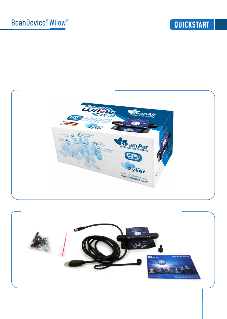
4.1 UNBOXING YOUR BEANDEVICE®WILOW®
Open the BeanDevice®Wilow®Box
The BeanDevice®Wilow®is provided with a USB cable, a magnet,
M8 Cap and four screws with locknuts
Figure 1 :BeanDevice®Box
Figure 2 :BeanDevice®Pack
7
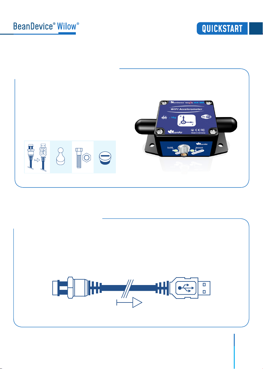
4.3 M8 TO USB 2.0 CABLE
Figure 4 :USB to M8 cable
4.2 ACCESSORIES DESCRIPTION
Figure 3 :BeanDevice®Wilow®AX-3D
The BeanDevice®WiLow®comes with additional accessories,
useful for the proper functioning of the device :
• M8 to USB 2.0 Cable
• Magnet to Power ON/OFF your device
• Four screws+Locknut
• M8 Plastic Cap
The USB cable is used to power supply the BeanDevice®WiLow®and to setup the
Network configuration. It is an M8-6 Pins plug / USB 2.0 cable, used to connect the
BeanDevice®WiLow®to the computer.
It is important to notice, that the M8-6 Pins side of the cable should be plugged
correctly on the device socket, respecting the notch.

8
4.4 MAGNET
Figure 5 : Power on/o and Network Reset
Network ResetPower ON/OFF Button
Neodymium Magnet
To avoid any accidental misconfiguration while installing and using the BeanDevice®
Wilow® ,a magnet is used to command the BeanDevice®instead of mechanical
push button. To Power ON/Power OFF the BeanDevice®or to make a Network Reset,
all you have to do is to point the magnet toward one of the two white circles as shown
on the next picture.

9
4.5 LOCKNUTS AND SCREWS
Figure 6 : Screws and Locknuts
4.6 M8 PROTECTION CAP
Protection Cap
Figure 7 :Protection Cap
The plastic cap is used to cover
the connector of the BeanDevice®
WiLow®as a protection. It should
be removed when connecting the
USB 2.0 cable.
Inside the packet, you will find four screws and four locknuts that will be used
to mount the BeanDevice®WiLow®on the four sides. A correct mounting is
essential to the success of your monitoring system.
Do not forget to tighten correctly the M8 cap otherwise you will loose
the waterproofness

10
4.7 CONNECTORS AND LEDS
Figure 8 :Connectors and Leds overview on BeanDevice®Wilow®
Activity/failure led
Radome Antenna
Battery status LED
Radome Antenna
M8-6Pins socket for
USB and power supply
Do not turn the Radome Antenna , you will unscrew it from its base and the device
will not work properly

11
4.7.2 Battery Charge LED description
Magnet
Operation ID Operations on Non-contact buttons Network LED
3
1Activity/Failure LED blinks in Green twice,
then will blink in Green Color every 10s
(default Data Acquisition mode).
2
4
After 5s, Activity/Failure LED will blink
one time in Red .
After 10s, Activity/Failure LED will blink
one time in Red, then will constantly
blink in Red. To come out from AP mode
refer to Operation n° 3
After 10s/15s, Activity/Failure LED blinks
in Red during 2s then twice in Green
To power ON the BeanDevice® WiLow® hold the
magnet on ON/OFF Label
To power o the BeanDevice® hold the magnet
on ON/OFF Label for 5s
To restore factory settings hold the magnet on
Network Label for 10s (Battery saver mode
disabled) or 15s (battery saver mode enabled)
To configure the BeanDevice® on Access Point
(AP) Mode, make sure that you device was
previously powered o , then hold the magnet on
ON/OFF Label for 10s
4.7.1 Operations on non-contact buttons and Network LED
Action Battery Charge LED
LED OFF.
External Power supply is not connected
Green LED ON: Battery charged
Red LED ON: Battery not charged
External Power supply is connected

12
5. HOW TO CONNECT MY BEANDEVICE®WILOW®
TO MY WIFI NETWORK
Figure 9 : BeanScape® WiLow®RA icon
The next step is to start the BeanDevice®WiLow®by pointing the magnet toward
the ON/OFF Button, and connecting it via the M8/USB cable to your computer.
Figure 10 : Connecting BeanDevice®WiLow®to a PC through
the M8/USB Cable Adapter
2.
1. Firstly, install BeanScape® WiLow®software, then run
it by double clicking on the BeanScape®icon on the
desktop.
To connect the BeanDevice®WiLow®, for the first time or after a network reset, to your
WIFI Network, it is recommended to follow the next steps of configuration:
M8/USB cable
M8-6 PinsUSB 2.0
Third-party wifi Access Point
Before to start to configure your Beandevice®wilow®, make sure that your PC is connected
to a WIFI AP. You need to connect your Beandevice®wilow®to the same WIFI AP.
13
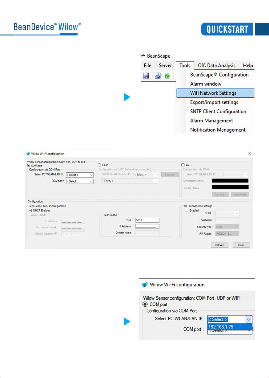
On BeanScape®software Menu bar,
select Tools and choose the option
WIFI Network settings
Figure 11 :WLAN Configuration on
BeanScape®menu
The following configuration window will appear
Figure 12 :Wilow®WIFI Configuration
Figure 13 :Frame Configuration via
COM port
On configuration via COM port frame,
select your Computer IP address
4.
3.
5.

14
Figure 14 : COM port configuration
Figure 15 : Enabling DHCP
Select the right serial port assigned to
your BeanDevice®WiLow®.
If there is more than one BeanDevice®
connected to your computer, or another
kind of devices using COM serial port, you
have to select the suitable port assigned
to your BeanDevice®WiLow®.
Enable DHCP on the TCP/IP configuration
frame to let the Access Point allocate a
dynamic IP address to the BeanDevice®
WiLow®
Enable the Wi-Fi configuration
and enter the WIFI Access Point
connection parameters (SSID,
Password, Security type and RF
Region), then click on validate
Figure 16 :WIFI configuration
6.
7.
8.
To avoid network disconnections, select correctly your WIFI Region

15
Add BeanScape®to firewall, from tools click on Advanced Settings then Add to
Firewall.
Now start the BeanScape®Server by clicking directly on the Green button or by
selecting Start the server from the Server option on the Menu bar
Figure 18 : Add to Firewall
Figure 19 : Start Server
10.
11.
The BeanDevice®profile will be displayed on your screen
If all parameters were filled correctly, a
validation window will pop up and let you
know that the configuration operation
has been completed successfully.
Figure 17 : Configuration Success
9.
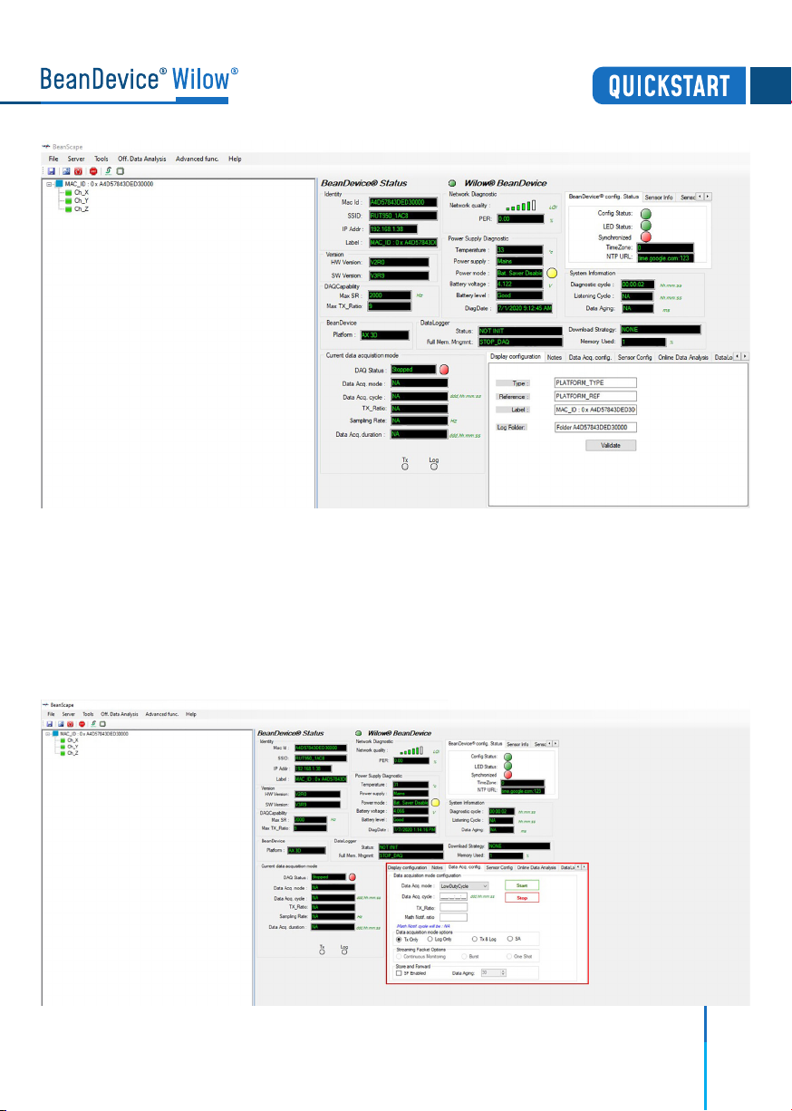
Figure 20 : BeanDevice®Dashboard
6. A QUICK OVERVIEW ABOUT DEVICE SETTINGS
6.1 How to setup a data acquisition
From the Beandevice®Wilow®main dashboard, go to the configuration frame and
select Data Acq. Config tab
1.
Figure 21 : Data Acq Config frame 16

Setup your Acquisition mode
Click on the sensor profile to see real-time measurement graph
By default, all the data measurement
will be located on the folder
C:\log_beanscape
2.
3.
Figure 22 : Data acquisition parameters
Figure 23 : Real-time graph
17
Find more info on the data acquisition modes available on the BeanDevice®Wilow®:
http://www.beanair.com/wa_files/TN-RF-18-Wilow-Wifi-Sensor-data
-acquisition-modes.pdf

18
Figure 24 : Data acquisition mode options
Figure 25 : DataLogger information on BeanScape®
6.2 Using the datalogger
The BeanDevice®Wilow®comes equipped with an embedded datalogger up to 5 millions
data points (with events dating).
You can start the datalogging from the previously demonstrated data acquisition tab.
you can select Log only as data acquisition option for only using the embedded datalogger
without transmitting data to BeanScape®or you can select TX & LOG for jointly save data
on your BeanScape®Host computer and also in the datalogger at the same time.
You can set the BeanDevice®WiLow®to SA (Stand Alone) in order to perform measurement
on its own not relying at any WiFi network .
You can monitor the Datalogger status , actual strategy of the datalogger after getting
full,download strategy and memory Rate used from BeanScape®.
From this window, you can monitor the datalogger status, Full memory management
and the memory rate used.

19
Figure 26 : DataLogger tab
These settings can be changed from the DataLogger tab at configuration panel
Brief information about datalogger status and progress download can be seen from
this tab
Figure 27 : DataLogger status
Other manuals for BeanDevice Wilow AX-3D
3
This manual suits for next models
3
Table of contents
Other BEANAIR Accessories manuals


Popular Accessories manuals by other brands


 owner's manual")


Sony
Sony PMW10MD brochure

Huawei
Huawei NetCol8000-C user manual

PCB Piezotronics
PCB Piezotronics 261A02 Installation and operating manual

DOL
DOL 44R-T Technical user guide

Backyard Discovery
Backyard Discovery ABERDEEN ARBOR 1905610 Owner's manual & assembly instructions

Hitachi
Hitachi EUP-O732T instruction manual