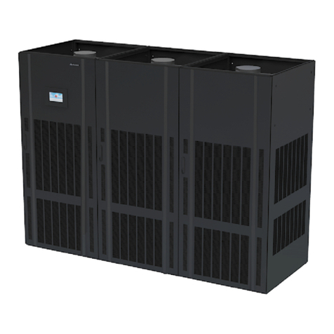
NetCol8000-C(070-260) In-room Chilled Water Smart
Cooling Product
User Manual
Copyright © Huawei Technologies Co., Ltd.
3.3.1 Removing the Packing.............................................................................................................................................42
3.3.2 Checking Fittings.....................................................................................................................................................42
3.4 Installing the Equipment.............................................................................................................................................42
3.4.1 Checking the Nitrogen Pressure ..............................................................................................................................42
3.4.2 Exhausting Nitrogen................................................................................................................................................44
3.4.3 Removing the Pallet.................................................................................................................................................46
3.4.4 (Optional) CabinetAssembly (Applicable only to Downflow Units with Four Doors)...........................................47
3.4.5 (Optional) Moving the Cabinet to the Installation Position (Disassembled Cabinet)..............................................52
3.4.6 Securing Equipment.................................................................................................................................................54
3.4.7 Lowering a Fan (Applicable To Downflow Units) ..................................................................................................55
3.5 Connecting Pipelines..................................................................................................................................................60
3.5.1 Cabinet Hole Positions ............................................................................................................................................60
3.5.1.1 Holes in the Side Panel.........................................................................................................................................61
3.5.1.2 Holes at the Bottom ..............................................................................................................................................63
3.5.2 Connecting the Chilled Water Pipe..........................................................................................................................63
3.5.2.1 Upflow..................................................................................................................................................................65
3.5.2.1.1 Bottom Pipe Routing .........................................................................................................................................65
3.5.2.1.2 Side Pipe Routing ..............................................................................................................................................66
3.5.2.2 Downflow.............................................................................................................................................................69
3.5.2.2.1 Bottom Pipe Routing .........................................................................................................................................69
3.5.2.2.2 Side Pipe Routing ..............................................................................................................................................70
3.5.3 Connecting Water Pipes...........................................................................................................................................73
3.5.3.1 Connecting the Drainpipe.....................................................................................................................................73
3.5.3.2 (Optional) Connecting the Water Inlet Pipe for the Wet Film Humidifier............................................................75
3.5.4 (Optional) Leakage Test with Nitrogen....................................................................................................................76
3.5.5 Leakage Test with Water..........................................................................................................................................78
3.6 Cable Connections......................................................................................................................................................81
3.6.1 Precautions...............................................................................................................................................................81
3.6.2 Positions of Electric Ports........................................................................................................................................81
3.6.3 Connecting Power Cables........................................................................................................................................84
3.6.4 Connecting Signal Cables........................................................................................................................................95
3.6.5 Teamwork Networking and Monitoring...................................................................................................................97
3.6.5.1 Main Control Module ...........................................................................................................................................97
3.6.5.2 Connecting the CAN Teamwork Network Cable..................................................................................................97
3.6.5.3 Connecting the Monitoring Network Cable........................................................................................................100
3.6.6 (Optional) Connecting the Water Leakage Sensor.................................................................................................102
3.6.7 (Optional) Connecting the Gravity Damper (Applicable To Upflow Units)..........................................................104
3.6.8 (Optional) Connecting the Motorized Damper (Applicable To Downflow Units) ................................................104
3.6.9 (Optional) Connecting the T/H Sensor Outside the Cabinet..................................................................................105
3.6.10 (Optional) Connecting the Direct free-cooling plenum.......................................................................................107
3.6.11 (Optional) Connecting a Differential Pressure Sensor.........................................................................................108
3.6.11.1 Connecting an Upflow Differential Pressure Sensor ........................................................................................108

