BEARMACH HawkEye PRO User manual
www.bearmach.com
HawkEye Pro
www.bearmach.com
Bearmach Limited
Unit 8, Pantglas Industrial Estate, Bedwas, Caerphilly,
CF83 8GE United Kingdom
Tel: +44 (0) 2920 856550 Fax: +44 (0) 2920 865586
email: [email protected]
User Manual

Bearmach HawkEye Pro
User Manual
02/2012 - EN(1.0)

Contents
i
Introduction
Overview.................................................................... 1
Getting Started ........................................................ 2
Additional Vehicle Manufacturers ............................. 2
Kit Contents ............................................................ 3
Display Screen........................................................... 4
Keypads .................................................................... 4
Left-hand keypad .................................................... 4
Right-hand keypad .................................................. 4
Connection ................................................................ 5
Diagnostic Connector Location................................ 6
Safety Precautions..................................................... 7
HawkEye Pro Menus
User Menu................................................................. 8
DTC Lookup .............................................................. 8
Language Menu......................................................... 9
Self Test Menu........................................................... 9
Software Version Menu............................................ 10
Security Menu.......................................................... 10
iMUX Harness (Firmware update) ............................. 12
Land Rover Systems
Anti-Lock Braking System (ABS).............................. 13
Longitudinal Acceleration Sensor Calibration ......... 13
Airbag...................................................................... 13
Restraints Build Mode Entry / Exit.......................... 13
Crash Reset .......................................................... 13
Air Suspension System (Ride Level Module - RLM) .. 14
Set Operating Mode .............................................. 14
Normal Mode ........................................................ 14
Manufacturing Mode ............................................. 14
Set Tolerance Control............................................ 14
Normal Tolerances ................................................ 14
Tighter Tolerances ................................................. 15
Deflation Routines ................................................. 15
Exit Deflate Mode .................................................. 15
Air Suspension System (EHC2) ................................ 16
Actuators............................................................... 16
Level Selection ...................................................... 16

Contents
ii
Drive Outputs ......................................................... 16
Set Operating Mode ............................................... 17
Deflation Routines .................................................. 18
Inflation................................................................... 19
Inflation Routines .................................................... 19
Steering Angle Sensor (SAS)..................................... 20
Steering Angle Sensor (SAS) Calibration ................. 20
Longitudinal Acceleration Sensor Calibration .......... 20
Service Reset ........................................................... 20
Service Interval Reset ............................................. 20
Oil Degradation Counter Reset ............................... 20
Electronic Parking Brake (EPB) ................................. 22
Unjam Electronic Parking Brake.............................. 22
Mounting Position................................................... 22
Latching Position.................................................... 23
Longitudinal Accelerometer Calibration................... 23
General Information
Cleaning ................................................................... 25
Display Screen ....................................................... 25
Software Updates..................................................... 25
Specification ............................................................. 25
Declaration of Conformity ......................................... 26
Diagnostic Cables
Cable Identification ................................................... 27
Optional cables ...................................................... 27
Menus
HawkEye Pro Menu Structure................................... 29
Menus - Diesel Engine .............................................. 41
Diesel Engine - TD5................................................ 41
Diesel Engine - Diesel EMS..................................... 42
Diesel Engine - EDC 1.3.1 ...................................... 42
Diesel Engine - DDE 4.0 ......................................... 42
Diesel Engine.......................................................... 43
Diesel Engine - DDE 4.0 ......................................... 43
Diesel Engine - Diesel EMS..................................... 43
Diesel Engine - Diesel EMS..................................... 44

Contents
iii
Menus - Petrol Engine ............................................. 44
Petrol Engine - 14CUX........................................... 44
Petrol Engine - GEMS............................................ 45
Petrol Engine - EMS 2000 ..................................... 45
Petrol Engine - MEMS 1.9 ..................................... 46
Petrol Engine - MEMS 3 ........................................ 47
Petrol Engine - MS43 ............................................ 48
Petrol Engine - Petrol EMS .................................... 48
Petrol Engine - M 5.2.1.......................................... 48
Petrol Engine - ME 7.2........................................... 49
Petrol Engine - Petrol EMS .................................... 49
Menus - Transmission.............................................. 50
Transmission - JATCO........................................... 50
Transmission ......................................................... 50
Transmission - GS 8.87.0/1................................... 50
Transmission - GS 2-38......................................... 50
Transmission - ZF / EGS 8602............................... 51
Transmission - GM5 / EGS20................................ 52
Transmission ......................................................... 53
Menus - Anti-lock Braking System (ABS) ................. 54
ABS - WABCO ‘D’................................................. 54
ABS - MK20 / MK25 ............................................. 55
ABS....................................................................... 55
ABS - WABCO ‘C’................................................. 56
ABS - Bosch 5.7 ................................................... 56
ABS....................................................................... 56
Menus - Airbag ........................................................ 57
Airbag - Autoliv AC4 .............................................. 57
Airbag - Siemens SRE Smart................................. 57
Airbag.................................................................... 57
Airbag - TRW SPS................................................. 57
Airbag - TRW Gen 4 .............................................. 57
Airbag - TRW MRS 4............................................. 58
Airbag.................................................................... 58
Menus - Climate control........................................... 59
Climate Control...................................................... 59
Climate Control...................................................... 59
Menus - Air Suspension........................................... 60
Air Suspension - Airsus.......................................... 60
Air Suspension - EHC2.......................................... 61

Contents
iv
Menus - Chassis....................................................... 63
Chassis - ACE........................................................ 63
Chassis .................................................................. 63
Chassis .................................................................. 64
Menus - Security ...................................................... 65
Security - 10AS ...................................................... 65
Security - CCU ....................................................... 66
Security - EWS 3D.................................................. 66
Security .................................................................. 67
Security - BCU ....................................................... 67
Security - GM3 Body Electrics................................ 69
Security - BeCM Body Electronics.......................... 70
Security - GM3 Body Electrics................................ 72
Security - Body ...................................................... 72
Security - VIM......................................................... 72
Menus - Steering Angle Sensor (SAS)....................... 73
SAS........................................................................ 73
SAS........................................................................ 73
SAS........................................................................ 73
Menus - Service Reset.............................................. 74
Service Reset ......................................................... 74
Service Reset ......................................................... 74
Menus - Electronic Parking Brake (EPB) ................... 75
EPB........................................................................ 75
Menus - Fuel-Burning Heater.................................... 76
Fuel-Burning Heater ............................................... 76
Fuel-Burning Heater ............................................... 76
Menus - Global DTC Clear........................................ 77
Global DTCs........................................................... 77

Introduction
1
Introduction
Overview
Nearly every new road vehicle, and many older vehicles, have multiple control modules
that monitor and control different aspects of the vehicle (e.g. Engine, Transmission,
Body, Suspension). The HawkEye Pro service tool has been specifically designed to
connect to, and communicate with, a number of these control modules and allow the
user to extract information (e.g. Diagnostic Trouble Codes) which may aid in the
diagnosis of system problems.
The vehicle coverage available on the HawkEye Pro service tool is as follows.
Available vehicle coverage.
• Defender
• Defender (L326)
• Freelander 1
• Freelander 2 (L359)
•DiscoveryI
•Discovery2
•Discovery3
•Discovery4
• Range Rover Classic
• Range Rover (P38a)
• Range Rover (L322)
• Range Rover Sport (L320)
OM1563

Introduction
2
Getting Started
Connect the EOBD cable (BA5083) to the HawkEye Pro service tool and the vehicle's
diagnostic connector. Once connected, the current software version number is
displayed.
Unlocking New Manufacturers
A new or updated HawkEye Pro service tool requires a security key to unlock the Land
Rover application and any other specific vehicle manufacturer. To register the HawkEye
Pro service tool, email technical.support@omitec.com including the serial number of the
unit, extra Vehicle Manufacturer required and contact details.
After obtaining your security key, follow this procedure to unlock the service tool.
1. Select ‘User Menu’ from the main menu.
2. Select 'Security' from the user menu.
3. Select 'Enter Security Key' from the security menu.
4. Using the and keys, scroll through the alpha/numeric character list.
5. Confirm each character by pressing the key.
If you make a mistake use the key and enter the correct character. To re-enter
the code from the beginning, press the key.
6. When prompted to verify the security key, press to confirm.
7. Power down the HawkEye Pro service tool by disconnecting the USB cable from
the tool.
8. Reconnect the USB cable to restart the HawkEye Pro service tool. The screen
should now show a list of the applications included.
Additional Vehicle Manufacturers
To add vehicle manufacturers to the HawkEye Pro service tool, contact your local
supplier.

Introduction
3
Kit Contents
HawkEye Pro kit
1. HawkEye Pro service tool
2. J1962 cable (BA5083)
3. USB cable
4. Carry case
5. Quick reference guide (not shown)
OM1666
3
2
4
1

Introduction
4
Display Screen
The HawkEye Pro service tool screen is a backlit LCD capable of displaying four rows
of text containing up to twenty characters.
Keypads
The HawkEye Pro is operated via the two keypads.
Left-hand keypad
Right-hand keypad
Key Function
Scrolls left and right.
Provides context sensitive help (where available).
Key Function
Scrolls up within a menu or text.
Scrolls down within a menu or text.
Selects a menu option, Continue or Yes.
Exits a menu or No.
OM1571
OM1570
Introduction
5
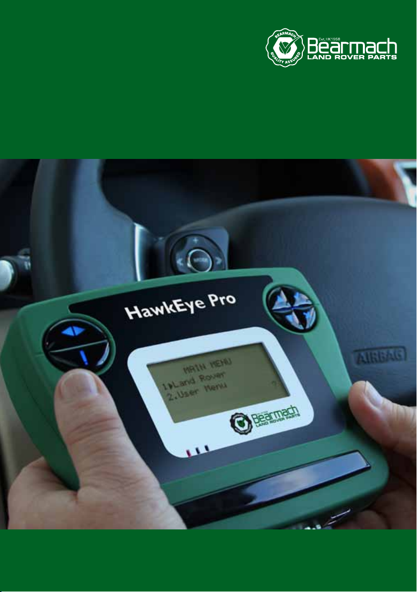
Connection
The HawkEye Pro service tool has a 25-way connector through which it can
communicate to the vehicle via various interface cables. Connection to the specific
system is via either the vehicle's EOBD (J1962) diagnostic socket or by a system specific
connector. Refer to the 'Vehicle Application List' to determine the correct cable.
When connecting the cable to the HawkEye Pro service tool, always secure the cable
with the fixing screws to prevent accidental disconnection during use.
1
2
OM1568
Introduction
6
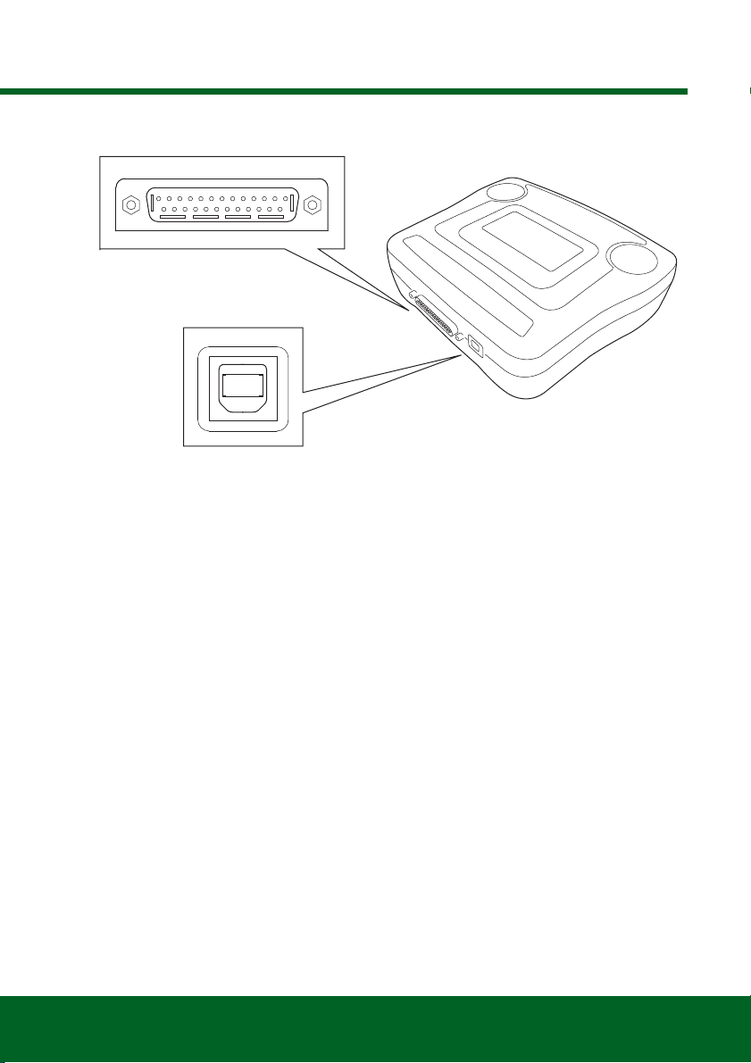
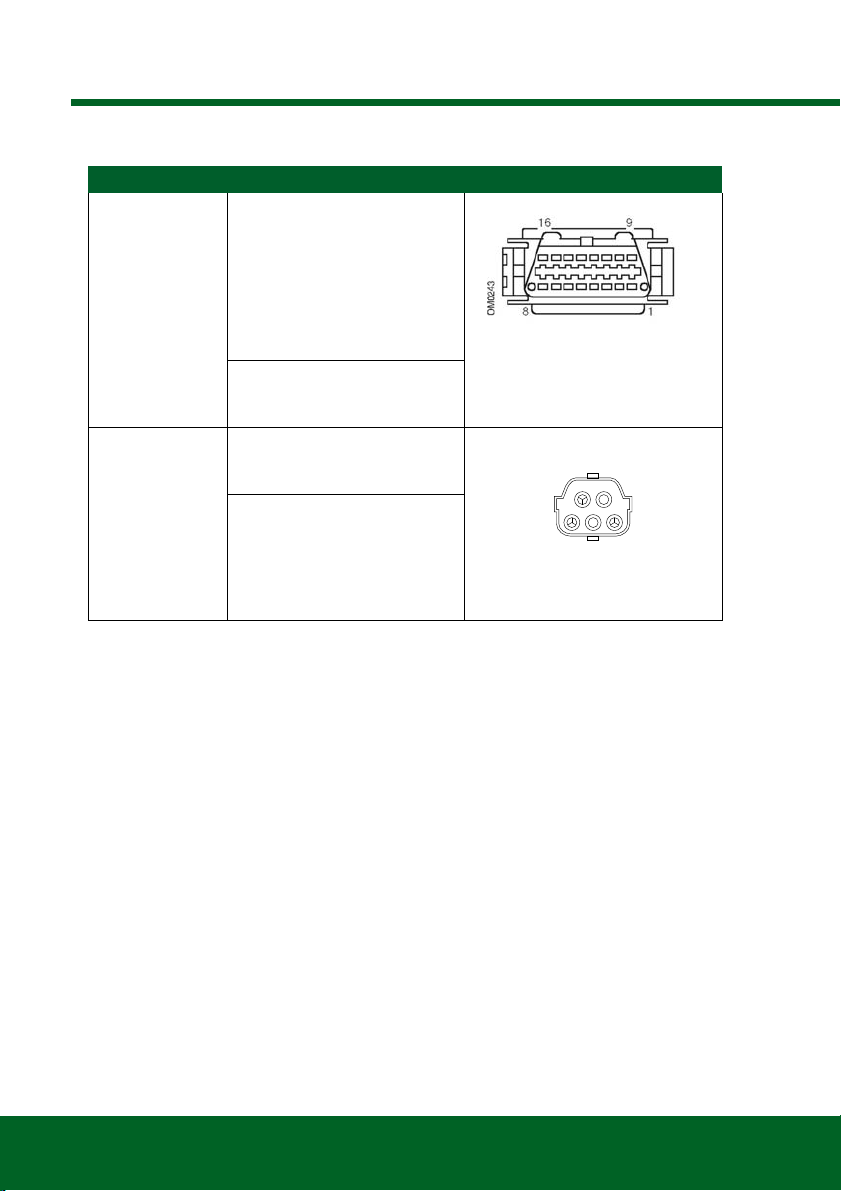
Diagnostic Connector Location
Troubleshooting
If communications cannot be established with the vehicle, follow the procedure below.
1. Check the correct system was selected from the menu.
2. Check the correct cable was used against the application list.
3. Disconnect both ends of the cable and ensure that no pins are bent or snapped.
4. Reset the control module on the vehicle by turning the ignition OFF and ON,
reconnect the service tool and try again.
If communications still cannot be established, contact the Product Support Team for
further assistance.
Connector Connector Location Connector Face View
J1962 In the driver / passenger
footwell on:
Defender (L316)
Freelander
Discovery I, 2, 3 and 4
Range Rover (P38a)
Range Rover (L322)
Range Rover Sport (L320)
Under the driver / passenger
seat on:
Defender
14CUX Behind the driver side kick
panel on:
Discovery I (V8)
Under driver / passenger seat
on:
Range Rover Classic
OM1557

Introduction
7
Safety Precautions
The following guidelines are intended to ensure the safety of the operator whilst
preventing damage to the electrical and electronic components fitted to the vehicle.
Equipment - prior to commencing any test procedure on the vehicle, ensure that the
HawkEye Pro service tool, its harnesses and connectors are in good condition.
Polarity - always observe the correct polarity when connecting the HawkEye Pro service
tool to the vehicle battery
Before carrying out testing on a vehicle, the following procedure should always be
observed.
• Check the handbrake/parking brake is on.
• Check that neutral or park is selected.
• Keep test equipment and harnesses away from HT leads.
• Be aware of moving parts.
• Do not run engine in a confined space without adequate ventilation.

HawkEye Pro Menus
8
HawkEye Pro Menus
User Menu
Use the and keys to select the required function and press to confirm the
selection.
For more information, see ‘HawkEye Pro Menu Structure’, page 29.
Note: Press to return to the main menu.
DTC Lookup
This option is used to look up a DTC description.
Looking up a known DTC
1. Use the and keys to move the cursor under the required DTC character,
then using the and keys, change the characters as required.
2. Press the key to confirm the DTC.
3. Press to return to the user menu.
If the unit recognises the DTC, the screen will display the full description (for example,
P0100 - Mass or Volume Air Flow ‘A’ Circuit).
Where more than one description is available, a separate menu will appear for you to
select the appropriate option.
If a code is not recognised, the message ‘No Text Allocated for this Code’ is displayed.
User Menu
1. OBD DTC Lookup
2. Language Menu
3. Tester Setup
4. Self Test
5. Software Version
6. Security
7. CAN converter
8. iMux Harness

HawkEye Pro Menus
9
Language Menu
The language menu allows changing of the software language, if available.
Selecting an alternative language
1. Use the and keys to select the required language.
2. Press the key to confirm the selection.
Note: This menu is only enabled when more than one language is installed on the
HawkEye service tool. If no additional languages are installed, the message ‘Not
Enabled’ will be displayed and the display will return to the User Menu.
Self Test Menu
Selecting a test
1. Use the and keys to select the required test.
2. Press to confirm the selection.
3. Follow the on-screen instructions to carry out the specified test.
4. Press the or key to return to the Self Test menu.
SELF TEST MENU
1. Full Self Test
2. Flash Test
3. Memory Test
4. IIC Memory Test
5. Vehicle Com Test
6. PWM J1850 Test
7. CAN Comms Test
8. Key Pad Test
9. Display Test
10. Display All Clear

HawkEye Pro Menus
10
Software Version Menu
This menu displays the HawkEye Pro service tool software version number before
displaying a list of all software modules currently loaded onto the service tool, including
their version numbers.
Checking the software version
1. Use the and keys to scroll through the software module list.
2. Press the or key to return to the Self Test menu.
Security Menu
All of the applications on the HawkEye Pro service tool are ‘locked’ by a security key. To
unlock a particular application, the appropriate security key must be obtained from the
Product Support team and entered into the HawkEye Pro service tool. If the expected
applications are not displayed in the User Menu it could be that the security key has not
been entered or that it has been entered incorrectly.
To examine or enter a security key, enter the ‘Security’ option. The following menu will
be displayed.
Show SecurityKey
This option displays the SecurityKey on-screen.
1. Select ‘Show SecurityKey’ from the Security menu and press the key.
2. Press the or key to return to the Security menu.
If the security key is incorrect, ‘Key is Invalid’ will be displayed. Press the key for
further information.
SECURITY
1. Show SecurityKey
2. Enter SecurityKey
3. Unit Serial No.

HawkEye Pro Menus
11
Enter SecurityKey
This option is used to enter the security key to unlock the functions on the HawkEye Pro
service tool.
1. Select ‘Enter SecurityKey’ from the Security menu and press the key.
2. Using the and keys, scroll through the alpha / numeric character list.
3. Confirm each character by pressing the key.
In the event of a mistake, use the key and enter the correct character. To re-
enter the code from the beginning, press the key.
4. When prompted to verify the security key, press the key.
5. Restart the HawkEye Pro service tool either by disconnecting and then
reconnecting the power supply, or by holding down the , , and keys
simultaneously.
Note: Pressing the key at any point will display the on-screen instructions.
Note: The key can be pressed at any point to cancel input of the security key. The
original security key will be retained by the HawkEye Pro service tool.
Unit Serial No.
This option displays the serial number of the HawkEye Pro service tool on-screen.
The unit serial number will match the number on the back of the unit and should be
quoted when calling Product Support to ensure efficient resolution of any technical
issues. This number cannot be changed.
1. Select the ‘Unit Serial No.’ option from the Security menu and press the key.
2. Once the unit serial number has been noted, press the key to return to the
Security menu.

HawkEye Pro Menus
12
iMUX Harness (Firmware update)
The iMux harness option allows you to check and update the firmware.
Get FW Version / Boot Mode
1. Select the 'Get FW Version' item to display the current version of the firmware within
the Multiplex system.
2. Press to return to the User Menu.
3. Press to return to continue to put the Multiplex system into boot mode ready to
be updated. Follow the on screen instructions. The Multiplex system must be
reprogrammed once the message to re-power the cable has been displayed.
Disconnect the EOBD cable from the power and then reconnect. Now reprogram
by selecting the ‘Update FW version’ option in the Multiplex menu.
Update Firmware
This process should only be performed after the Multiplex system has been placed into
boot mode.
1. Select the 'Update FW Version' item the Multiplex systm will now be updated.
2. A message will be displayed to show the firmware has been updated. Press to
continue the update process
Note: The update process must be allowed to fully complete once started and the
power must not be interrupted during the update process.
IMUX HARNESS
1. Get FW Version
2. Update FW Version

Land Rover Systems
13
Land Rover Systems
Anti-Lock Braking System (ABS)
•Land Rover vehicles
Longitudinal Acceleration Sensor Calibration
This routine is necessary in the following situations.
• The Longitudinal Acceleration Sensor has been replaced.
• The ABS / TC / ESP control module has been replaced.
• The ESP system is not behaving properly as it should. Resetting of this sensor can
sometimes cure erroneous ESP behaviour.
Airbag
•Land Rover Freelander 2 (L359) (2007-)
Restraints Build Mode Entry / Exit
This function is used to place the Airbag / Restraint System in a ‘build mode’, to facilitate
safe maintenance and repairs to be performed without risk of detonation of airbags or
pretensioners. When work has been completed on the system, the Airbag / Restraints
system must be taken out of ‘build mode’ to restore normal operation.
Crash Reset
This option is necessary on vehicles where airbags have been deployed following a
crash. The routine clears the crash ‘flag’ in the Body Control Module to enable normal
operation after repair of the vehicle and installation of a new airbag.

Land Rover Systems
14
Air Suspension System (Ride Level Module - RLM)
•Discovery 3 (2005 - 2009)
•Range Rover Sport (L320) (2005 - 2009)
•Range Rover (L322) (2006 - 2009)
There are several functions available via the HawkEye Pro service tool.
• Set Operating Mode.
• Set Tolerance Control Mode.
• Deflation Routines.
Set Operating Mode
This procedure is used to set the RLM to different modes. Modes can be set under the
‘Configuration’ option of the HawkEye Pro service tool. The current operating mode can
be displayed under the ‘Live Data’ option of the HawkEye Pro service tool.
Pre-test conditions
• The ignition must be ON.
• An approved battery charger must be connected to ensure consistent power supply.
Normal Mode
This is the normal operating mode for the RLM.
Manufacturing Mode
This mode is mainly used in the factory when assembling the vehicle. It can, however,
also be used if the owner of the vehicle wishes to fit coil springs instead of the air springs.
Placing the control module in this mode ensures that the control module continues to
function in terms of processing information such as height information. This process will
render the Air Suspension controls and instruments non-functional.
Note: If the vehicle is driven in any mode other than Normal Mode, the Air Suspension
will NOT operate correctly.
Set Tolerance Control
This procedure is used to set the RLM tolerance control. Tolerance control can be set
under the ‘Configuration’ option of the HawkEye Pro service tool. The current tolerance
control state can be displayed under the ‘Live Data’ option of the HawkEye Pro service
tool.
Pre-test conditions
• The ignition must be ON.
• An approved battery charger must be connected to ensure consistent power supply.
Normal Tolerances
This state is the normal operating mode for the Air Suspension system.
Table of contents
Popular Medical Equipment manuals by other brands

Solta Medical
Solta Medical Fraxel 1550 Operator's manual

Therafin
Therafin SQUEEZE MACHINE owner's manual

ADC
ADC Diagnostix 2100 Instructions for use
Ossur
Ossur FORMFIT TRACKER quick start guide

Luxfer
Luxfer EasyPulse 1901-765 Series Instructions for use

Weinmann
Weinmann MEDUVENT Standard Instructions for use

Stryker
Stryker 6253 Operation & maintenance manual

BMC
BMC G3 B20A user manual

BCD microtechnique
BCD microtechnique COVIDAIR S/T EASY quick start guide

Richmar
Richmar SoundCare Plus instruction manual

Withings
Withings Sleep Installation and operating instructions

Magnamed
Magnamed VentMeter instruction manual


