Beastx MICROBEAST PLUS User manual

Version 5.0
QUICKSTART GUIDE

0118
STUDIOX.BEASTX.COM BEASTX.COM WIKI.BEASTX.COM

SAFETY NOTES
• Radio controlled (R/C) helicopters are no toys! The rotor blades rotate at high speed and pose potential
risk. They may cause severe injury due to improper usage. It is necessary to observe common safety
rules for R/C models and the local law. You can gather information from your local R/C model club or
from your national modelers association.
• Pay attention to your own safety and the safety of other people and property in your vicinity when
using our product. Always y in areas away from other people. Never use R/C models in close proximity
to housing areas or crowds of people. R/C models may malfunction or crash due to several reasons like
piloting mistakes or radio interference, and cause severe accidents. Pilots are fully responsible for their
actions, and for damage or injuries caused by the usage of their models.
• Please read the following instructions thoroughly before the rst use of your MICROBEAST PLUS and
setup the system carefully according to this manual. Allow sucient time for the setup procedure and
check each step carefully. Watch for a mechanically clean and proper build of your helicopter. A wrong
system setup can lead to a serious accident and damage to the model.
• Radio controlled (R/C) models consist of several electrical components. It is therefore necessary to
protect the model from moisture and other foreign subtances. If the model is exposed to moisture this
may lead to a malfunction which may cause damage to the model or a crash. Never y in the rain or
extremely high humidity.
• When operating the helicopter with a MICROBEAST PLUS ensure there is a suciently large and stable
receiver power supply. Because of the direct coupling of the rotor blades to the servos, without the use
of a ybar mixer, the servos are exposed to increased actuating forces. In addition, because of the
intermediary electronic gyro system, the servos are driven more often than with traditional use. These
factors can make the power consumption increase a lot compared to a ybar helicopter. When the
supply voltage falls below 3.5 volts for a short amount a of time, the system will power o and reboot.
In this case a crash of the helicopter is unavoidable.
• Do not expose the MICROBEAST PLUS system to extreme variations in temperature. Before powering
up the system, wait some time so that the electronics can acclimatize and any accumulated
condensation is able to evaporate.
• The sensors of MICROBEAST PLUS consist of highly sensitive electromechanical components. These can
be damaged due to moisture or mechanical or electrical impact. Do not continue using this product, if
it has been exposed to such inuences, e.g. due to a crash of the model or due to overvoltage caused
by a defective receiver power supply. Otherwise a failure may happen any time.
• When operating electric helicopters make sure that the electric motor cannot start inadvertently during
the setup procedure. Particularly pay attention if using a single-line receiver and if the ESC is connected
directly to the MICROBEAST PLUS. We recommend disconnecting the electric motor from the ESC during
the setup procedure. Prior the rst usage please slide the motor/pinion away from the main gear, then
check that the motor does not to start inadvertently when the receiver is switched on.

• When operating the RPM Governor feature of MICROBEAST PLUS it is essential to ensure that the motor
cannot start by accident when making adjustment or performing preparations to start the engine.
Carefully read this manual and make sure you fully understand how the RPM Governor feature is
operated before making any adjustments. Also make sure the motor does not start when the radio link
is interrupted or when you switch on the transmitter initially. With electric driven models do not dock
the motor to the main gear unless all necessary adjustment procedures have been nished. Always
maintain sucient safety distance to the motor and other rapidly rotating components of the
helicopter.
• MICROBEAST PLUS with AttitudeControl can be used as a ying aid for beginners by limiting the
reaction of the helicopter to stick inputs and by stabilizing the helicopter with a electronic control loop.
However, this does not provide that the helicopter can always be own safely! By incorrect control
inputs the helicopter still may crash or be placed in a position in which the pilot becomes disoriented
even when using AttitudeControl. In addition, the helicopter can drift due to external inuences and it
is not guaranteed that the articial horizon of the device can stabilize the helicopter at any time and
recover from any orientation. Inuences such as temperature uctuations or vibrations may cause
incorrect results and distort the position calculation of the system in consequence. There is no
guarantee that the system will always work correctly. Only the pilot is responsible for the control of the
helicopter and thus also for the use of the system. Note that the system for technical reasons will not
hold the helicopter absolutely to the point. The unstable tendency of a helicopter will cause the model
to y in a certain direction even when using AttitudeControl. External inuences such as wind can
further strengthen this eect. In addition measurement inaccuracies of the sensors can distort the
position determination slightly. You must always be able to turn o the system immediately and be
able to take over full control of the helicopter.
• We suggest you to seek the support of an experienced helicopter pilot before you undertake the rst
ight of your model. Additionally, ight training with a R/C simulator can help make ying easier and
more enjoyable. Ask your local dealer if you need technical support or if you observe problems during
the usage of our system.
• AttitudeControl can help to facilitate ying of model helicopters by briey passing over control to the
system if the pilot becomes disoriented. By using the built-in articial horizon the helicopter can be
brought to a nearly horizontal position so that the pilot gains time to reorient. Thus, there can be no
assurance that the model is saved from a crash in general. Depending on the current attitude and the
speed of the model and depending on how fast the AttitudeControl is activated, the model may crash
before or while the system tries to recover. In addition, the helicopter can drift due to external inuences
and it is not guaranteed that the articial horizon of the device can stabilize the helicopter at any time
and recover from any orientation. Inuences such as temperature uctuations or vibrations may cause
incorrect results and distort the position calculation of the system in consequence. Strictly observe the
general safety rules for dealing with RC models and do not totally rely on the system. The pilot is
responsible for the control of the helicopter and thus also for the use of the system. You must always be
able to turn o the system immediately and be able to take over full control of the helicopter.

If you like to get more insight into the system and like to have a more visualized type of setup you
can use the StudioX App for PC/mac or StudioXm for your smartphone/tablet in combination with
the USB2SYS interface (PC/mac) or BLE2SYS interface (smartphone/tablet) (optional available).
These apps are the source to get even more out of your device like saving/restoring paramaters,
firmware updates, loading preset heli configurations and making advanced adjustment to fully
customize your MICROBEAST PLUS to your needs.
StudioX can be downloaded from:
STUDIOX.BEASTX.COM
Dear customer,
thank you for purchasing our product.
MICROBEAST PLUS is a high-end gyro system for RC helicopters that has been developed in Germany using
latest technology and setting high standards. It can be used with many different types of helicopters like
3D aerobatic helis, F3C competition helicopters as well as scale helicopters with 2 or more rotorblades. The
system comes with BASIC flybarless stabilization functionality and can be upgraded by paid update to the
PROEDITION. This enables additional features like AttitudeControl for recue bailout or constant leveling and a
feature called„Bank Switching“ which allows to switch between parameter presets in flight to serve different
flight conditions or flying styles.
To setup MICROBEAST PLUS there is no need for any additional devices. All you need is your radio system
and your helicopter. Thanks to the well proven„EasySetup“ concept you can do all the necessary adjustment
directly at the device and you‘re ready for take off within a few minutes.
This Quickstart Guide is a clearly arranged guide that will lead you step-by-step through the basic flight
setup. Please follow this guide carefully and make sure to read the attached safety notes. For a detailed
instruction manual and further details, tipps, tricks and notes about the product please visit
WIKI.BEASTX.COM
This guide is intended to be used with MICROBEAST PLUS firmware version 5.0.x
only! After power up when the Status-LED lights red, for a few seconds in the left row
menu LEDs Aand Cindicate major version„5“. In the right row no LED lights up.

1. HARDWARE INSTALLATION
You can position MICROBEAST PLUS flat or upright on the helicopter. The large socket must point to the front or to the rear of
the helicopter. The small white socket must be aligned with the longitudinal axis.
The sensor axis (housing edges of the device) must be aligned exactly parallel to all three rotation axis of the helicopter.
However, it is allowed to position the device offset from the rotation axis.
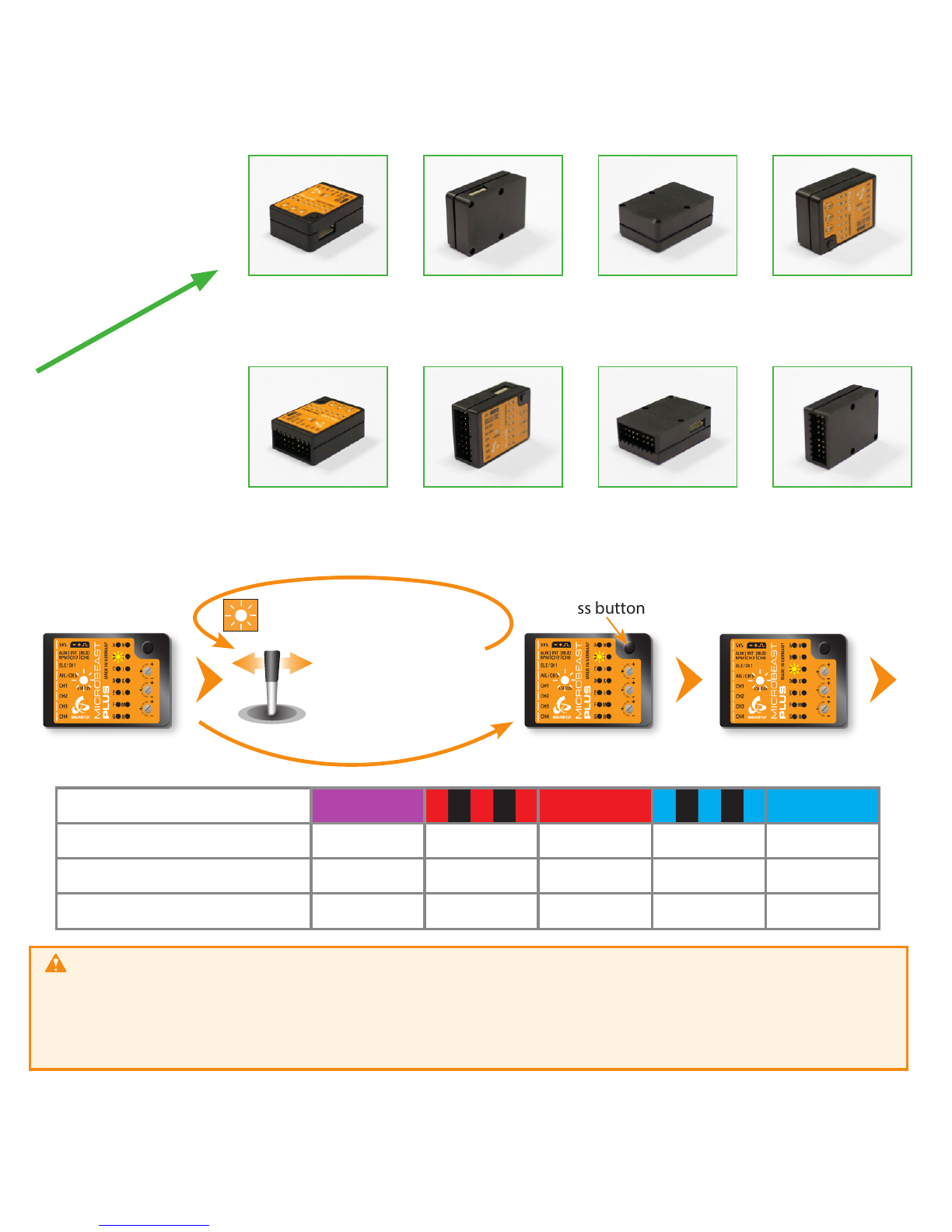
In summary there are 8 mounting orientations possible:
1. flat, sticker on top, socket pointing to front
2. upright, button up, socket pointing to front
3. flat, sticker showing to ground, socket pointing to front
4. upright, button down, socket pointing to front
5. flat, sticker on top, socket pointing to rear
6. upright, button up, socket pointing to rear
7. flat, sticker showing to ground, socket pointing to rear
8. upright, button down, socket pointing to rear
Use one of the supplied 3M gyro pads to stick the device to your helicopter. The device housing must not directly touch
the chassis of the helicopter. When connecting and laying out the servo and receiver wiring later onwards please make sure
the wires do not pass tension to the MICROBEAST PLUS. It is not recommended to bundle or tie down the leads close to the
MICROBEAST PLUS device.
1. 2. 3. 4.
5. 6. 7. 8.
Flight direction
ESC/Throttle
servo
BEC/Power supply
(if required)
JR® or
SPEKTRUM®
satelite
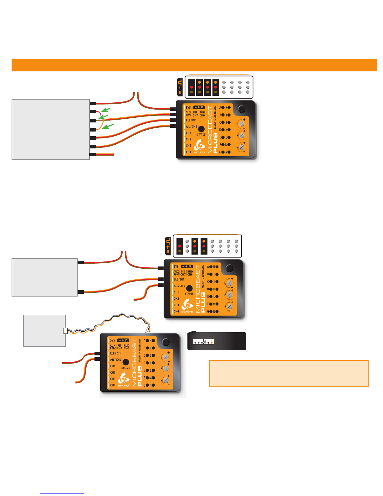
2. CONNECTING THE RECEIVER
BAT
Pitch
Gyro
Rudder
Elevator
Aileron
Throttle
STANDARD
RECEIVER
Throttle servo/ESC
red
brown
orange
BEC/Receiver battery
(if required)
BAT
SINGLELINE
RECEIVER
Throttle servo/ESC
BEC/Receiver battery
(if required)
Signal
Supported receivers/
transmission protocols:
• SRXL: JR® XBus (Mode B), Multiplex®
SRXL (V1+V2), Jeti® UDI, Graupner/SJ®
HOTT SUMD, Spektrum® SRXL
• Futaba® SBUS
• Remote satellite (Spektrum® DSM2/
DSMX, JR RJ-01 DMSS)
• Jeti® EXBUS
• ALIGN/FlySky iBus
• PPM serial signal (SPPM)
The illustrations are only
intended as examples! The
function assignment of the
transmitter determines which
channel on the receiver controls
which function.
Using a Single-Line receiver all channels/functions are transferred by one single connection wire. This allows to use even more
than 5 channels, i. e. for controlling the headspeed Governor, AttitudeControl function and additional output channels.
Always make sure the power supply is stable and dimensioned suciently for the intended application. If possible always
connect the power source directly to MICROBEAST PLUS (not at port [AUX|PIT|RUD]) but additional supply cables can be plugged
into free receiver ports, too. Especially when using standard size servos it is recommended to use more than one power supply
cable in parallel to preserve a stable voltage and to reduce power loss due to connection resistance..
The assignment of functions to the radio channels is mentioned in the manual of your radio system. Also you can nd out the
function assignment by checking your transmitter‘s servo monitor. The connectors of MICROBEAST PLUS are assigned to the
functions as follows:
AIL|CH5 = Aileron, ELE|DI1 = Elevator, RUD (orange wire) = Rudder, PIT (red wire) = Thrust, Aux (brown wire) = Gyro gain
The wires for aileron and elevator additionally transfer the power between MICROBEAST PLUS and receiver.
Using a single remote satellite is only recommended
for 450 size helis or smaller! For larger helis please use a
SRXL compatible Single-Line receiver for your radio brand.
ESC/Throttle
servo
BEC/Power supply
(if required)
JR® or
SPEKTRUM®
satelite
3. PREPARING YOUR TRANSMITTER
With electric driven models remove the motor from the main gear when performing the basic setup for
safety reason! Additionally deactivate the throttle by using the „Throttle HOLD“ switch, so the motor won‘t start to
turn when moving the thrust stick.
When flying a nitro or gasser heli remove the servo horn from the throttle servo before first power up to prevent
jamming the servo due to wrong servo setup.
You mustn‘t use any mixing functions on the output channels! Especially it is not allowed to use mixing functions for the
swashplate servos. Deactivate all output channels that are not used. In the basic configuration we only need pitch, aileron,
elevator, rudder, throttle and one channel to adjust the tail gyro gain.
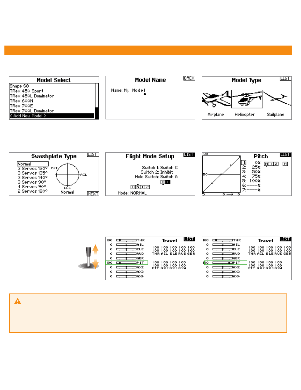
Create a new helicopter model memory in your transmitter that supplies different flight modes for controling throttle, pitch
and the tail gyro gain in different flight situations.
Only the pitch channel must
be controled when moving
the thrust stick. The same
applies to aileron, elevator
and rudder.
Each control function must exactly control one output channel. Initially the servo throws must be set to 100% and all
trims and sub trims must be zero. For the basic setup do not change the pitch curves yet. The throttle curves and throttle
servo settings can be adjusted as necessary for this model in case you do not intend to use the internal Headspeed Governor
function of MICROBEAST PLUS.
Make sure your transmitter is on and sending signals to the receiver. At menu point Ayou can start automatic receiver type
detection by briefly pressing the button once. The color and state of the Status LED indicates which type is currently scanned
for. When the receiver has been detected the menu will skip to point B; when there was some error the Status LED will flash
in red color and the menu stays at A. In this case please make sure you‘ve connected the receiver correctly and try again!
Single-Line receiver (Status LED off, purple or red at menu point A)
When at menu point Bpress and hold the button for 2 seconds to load the default function assignment that has been preset
for the detected radio system. Alternatively you may program a different function assignment manually in case the default
assignment does not match to your transmitter‘s function layout. How this works in detail you can read from the detailed
instruction manual which you can get at wiki.beastx.com.
Preset function assignment for the different single-line receiver protocols (indicated by Status LED color at A):
You mustn‘t use any mixing functions on the output channels! Especially it is not allowed to use mixing functions for the
swashplate servos. Deactivate all output channels that are not used. In the basic configuration we only need pitch, aileron,
elevator, rudder, throttle and one channel to adjust the tail gyro gain.
Create a new helicopter model memory in your transmitter that supplies different flight modes for controling throttle, pitch
and the tail gyro gain in different flight situations.
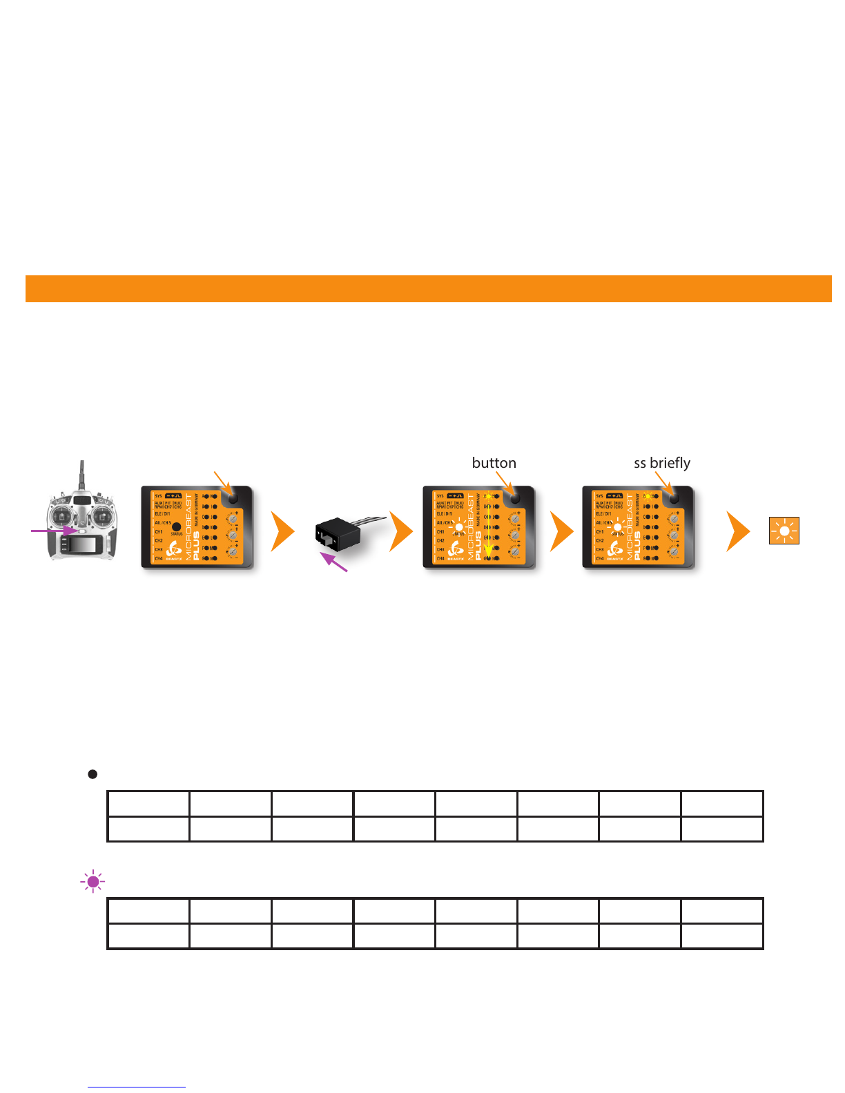
4. RECEIVER SETUP
Switch on
power supply Menu LED Aflashes
Status LED
changes color
(scanning for
receiver)
Make sure your transmitter is on and sending signals to the receiver. At menu point Ayou can start automatic receiver type
detection by briefly pressing the button once. The color and state of the Status LED indicates which type is currently scanned
for. When the receiver has been detected the menu will skip to point B; when there was some error the Status LED will flash
in red color and the menu stays at A. In this case please make sure you‘ve connected the receiver correctly and try again!
Single-Line receiver (Status LED off, purple or red at menu point A)
When at menu point Bpress and hold the button for 2 seconds to load the default function assignment that has been preset
for the detected radio system. Alternatively you may program a different function assignment manually in case the default
assignment does not match to your transmitter‘s function layout. How this works in detail you can read from the detailed
instruction manual which you can get at wiki.beastx.com.
Preset function assignment for the different single-line receiver protocols (indicated by Status LED color at A):
Press and hold button Press briefly
To enter RECEIVER MENU MICROBEAST PLUS must be switched off completely. Push and hold the button before and while
powering on. The menu LEDs will start to cycle from Ato N. Now you can release the button.
Release button
Menu LEDs cycling
Switch on
transmitter
THR AIL ELE RUD GER PIT AX2 AX3
Throttle [CH5] Aileron Elevator Rudder Gyro gain Pitch Aux [CH6] Governor*
Spektrum® DSM2/DSMX or JR RJ-01 DMSS remote satelite
12345678
Pitch Aileron Elevator Rudder Aux [CH6] Throttle [CH5] Gyro gain Governor*
PPM serial signal (SPPM)
To initiate bind procedure on a single Spektrum® remote satellite connect the Spektrum bind plug to [SYS] port. When
using a DSM2 remote satellite, push and hold the button and turn on power while still holding the button down. The LED on
the satellite will ash together with Menu LED Non the MICROBEAST PLUS. When binding a DSMX remote satellite do not
touch the button but only power on the device. The LED on the satellite will ash together with Menu LED H. Initiate the bind
procedure on the transmitter. Power o and remove the bind plug when nished successfully.
To bind the JR® RJ01 remote satellite initiate the bind procedure on the transmitter and power on the MICROBEAST PLUS.
The remote satellite will bind instantly. Connecting a bind plug or similar is not necessary.
* Governor channel is used to set headspeed for governor function with nitro or gas driven helicopters
Receiver with „Standard“ 5-wire layout (Status LED blue at menu point A)
Here the function assignment is simply determined by the order of physical connection of the wires to the receiver outputs. Assignment
by software is not provided and will not appear when choosing this type of receiver. When a „Standard“ receiver (Status LED blue at
menu point A) was detected the receiver setup is finished and the system will reboot immediately. Menu point Bwill not appear!
WARNING: At menu point Nthe throttle output CH5 is active, when using a electric helicopter the motor
may start to run! Move the throttle to the desired failsafe position which will be set in case the receiver connection is
interupted oder gets disconnected.
When pushing the button after setting throttle failsafe position all the receiver settings will be stored. Then all menu
LEDs will flash repeatedly and the system will reboot after 3 seconds.
12345678
Pitch Aileron Elevator Rudder Aux [CH6] Throttle [CH5] Gyro gain Governor*
Graupner®SUMD
THR AIL ELE RUD GER PIT AX2 AX3
Throttle [CH5] Aileron Elevator Rudder Gyro gain Pitch Aux [CH6] Governor*
Spektrum® SRXL
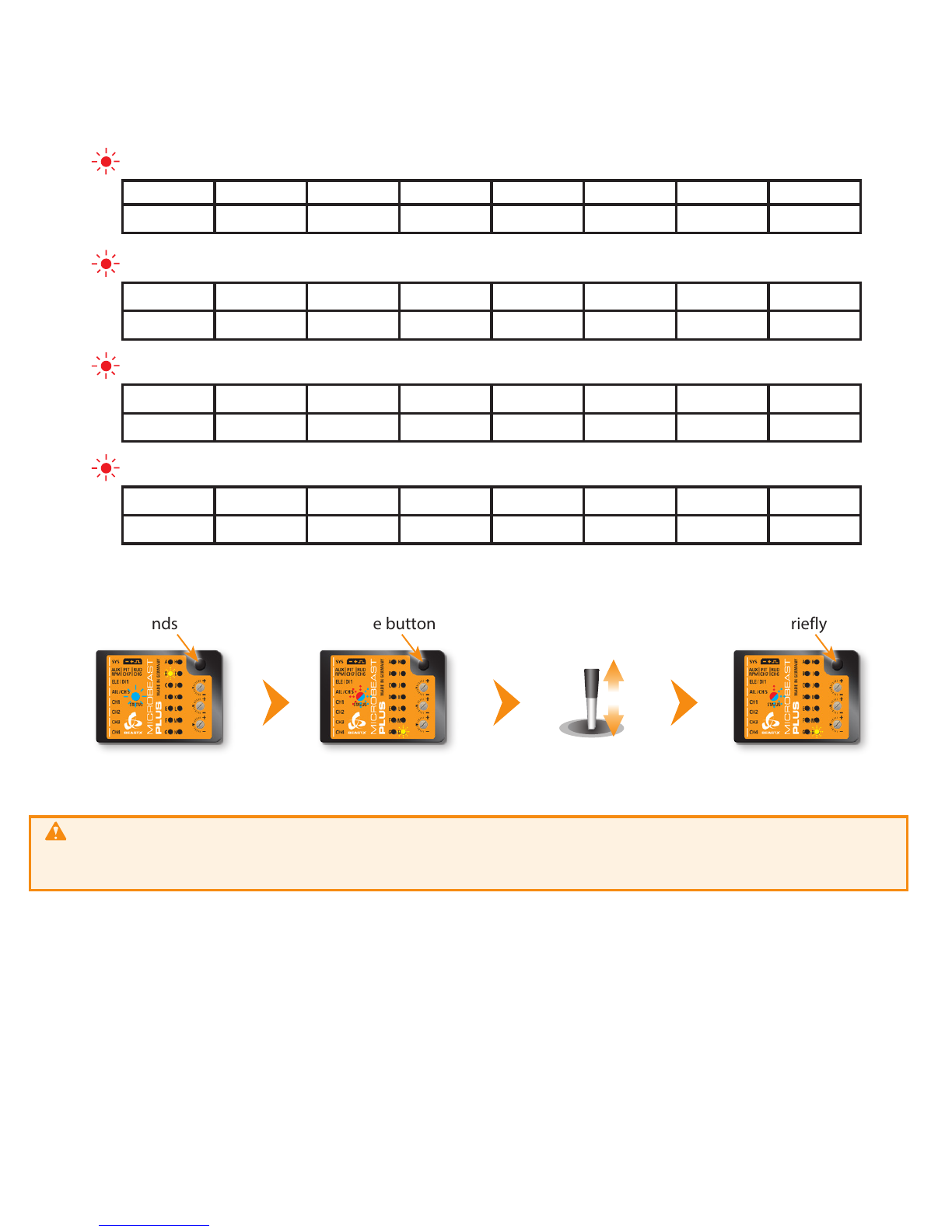
Then enter SETUP MENU for making the basic adjustments
Setup menu point A- Device orientation (Menu LED A solid lit up)
Check the selected device orientation and change it if necessary by (repeatedly) moving the rudder stick into one direction
until the Status LED color corresponds to the real device orientation. Then briefly push the button to save the setting and
to proceed to the next menu point.
12345678
Aileron Elevator Throttle [CH5] Rudder Gyro gain Pitch Aux [CH6] Governor*
Futaba® SBus/SBus2 or BEASTX FASST compatible receiver
12345678
Aileron Elevator Rudder Pitch Throttle [CH5] Gyro gain Aux [CH6] Governor*
Multiplex®SRXL v1 and v2, JR®XBUS Mode B, JETI®UDI 12 + 16ch
Menu LED Bflashes
Status LED is solid blue
Press and hold button
for 2 seconds Release button
Menu LED Nflashes
Status LED flashes red/blue
Press briefly
Make sure throttle is
in motor stop/failsafe
position

When pushing the button after setting throttle failsafe position all the receiver settings will be stored. Then all menu
LEDs will flash repeatedly and the system will reboot after 3 seconds.
Move rudder stick
left or right
5. BASIC HELI SETUP (SETUP MENU)
Status LED lights up
blue or purple
Operation mode
Then enter SETUP MENU for making the basic adjustments
Setup menu point A- Device orientation (Menu LED A solid lit up)
Check the selected device orientation and change it if necessary by (repeatedly) moving the rudder stick into one direction
until the Status LED color corresponds to the real device orientation. Then briefly push the button to save the setting and
to proceed to the next menu point.
Operation mode
(Status LED blue or purple)
Press and hold (!) button
Menu LED Aflashes
(= PARAMETER MENU A)
Keep button pressed
for 2 seconds
Menu LED Alights solid
(= SETUP MENU A)
Release button when
LED Astops flashing
Status LED shows currently
selected device orientation Status LED shows currently
selected device orientation Menu LED Bsolid
(= SETUP MENU B)
Press button briefly
Status LED changes color/state
(= Changing device orientation)
Calibration of
radio channels
Do not move sticks on
the radio!
Calibration of sensor
rest positions
Do not move the
helicopter!
Firmware version: 5.0.x
After power up or finishing RECEIVER MENU adjustment wait until the system has initialized
Status LED off* Status LED
flashing purple Status LED purple Status LED
flashing red
Large socket points
to nose of the heli
Status LED red Status LED
flashing blue Status LED blue Status LED flashing
red/blue
Large socket points
to tail of the heli
Status LED shows current
swashplate update frequency SETUP MENU C
Press button briefly
Status LED shows current
swashplate servo frame rate
Status LED purple ashing red red ashing blue blue
BSwashplate update rate 50 Hz* 65 Hz 120 Hz 120 Hz 200 Hz
CRudder servo pulse width 760 µs - 960 µs - 1520 µs*
DRudder update rate 50 Hz* 120 Hz 270 Hz 333 Hz (560 Hz)
If you don‘t know the which update rate is best for your servos never use more than 50Hz.
The higher the update rate the better it is for the flight performance of MICROBEAST PLUS but you must check the servo specifications
before increasing the update rate. Otherwise the servos may get damaged! For a list with parameter examples for most common servo
types see WIKI.BEASTX.COM.
Always use 1520 µs rudder servo pulse width except you‘re using a very special type of rudder servo with reduced pulse width (only these
servo can be used with an increased update rate of 560 Hz!). Check the servo data sheet!
...
Move rudder stick
left or right
Status LED changes color/state
(Changing swash servo frame rate)
Flight direction
Setup menu points B, Cand D
Adjust swashplate update rate (B), rudder servo pulse width (C) and rudder update rate (D) again by moving the rudder
stick to one or another direction until the Status LED lights in the correct color necessary for the servos used in your helicopter.
Briefly pressing the button will store the selected option and skip to the next menu point.
Menu LED Esolid
Status LED off Use rudder stick to move the servo to
the maximum allowed deflection Release rudder stick Status LED
blue or red
Use rudder stick to move the servo to the
minimum allowed deflection Release rudder stick Status LED
purple
Press button briefly
Menu LED Fsolid
(= SETUP MENU F)
Setup menu point E- Rudder servo limit
Plug the rudder servo connector into [CH4] output of MICROBEAST PLUS. Put the servo arm on the servo so that it forms
roughly an angle of 90 degrees with the rudder linkage rod and adjust the length of the linkage rod as described in the
helicopter manual.
Push and hold the rudder stick into one direction to move the rudder servo and release the stick when the servo reaches the
maximum or mimimum allowed servo throw. Using the rudder stick you can reposition the servo at any time to adjust the
exact servo limit. If you do not touch the rudder stick for several seconds the current servo position will be saved as maximum
or minimum (the Status LED will flash and then light up solid in blue or red color). Then move the servo to the opposite
direction, adjust as described above and wait until also this position gets stored (now Status LED becomes purple).

Setup menu point F- Rudder direction
1. Move the rudder stick and check the rudder direction on the helicopter
Correct Wrong
Rudder stick to the right
Tail rotor pushes tail left, so heli turns to right. Tail rotor pushes tail right, so heli turns to left.
If the stick is moving the servo into the wrong direction use
the servo reverse function of your transmitter and reverse
the rudder channel to change stick control direction.
2. Now set the rudder direction of the MICROBEAST PLUS gyro
When you move the rudder stick to the right, the Status LED must light up or flash in blue color. When you move the rudder stick to the
left, the Status LED must light up or flash in red color. When the display is inverted (red = right and blue = left) reverse the display (internal
control direction) by tapping the aileron(!) stick once.
Status LED blue
Rudder stick to the right
Correct
Status LED red
Wrong
Tap aileron stick to
swap colors
3. Optional: When you move the rudder stick to full deflection, the Status LED should light solid, not just flash. If this is not the case, increase
the servo throw/endpoint of the rudder channel in the transmitter just as far so that the Status LED changes from flashing to solid
when the rudder stick reaches the end position. Note: Do not increase the endpoint too much in the transmitter. We need an exact
match of full stick position and stick end position, the Status LED should just change from flashing to solid when reaching the end position.
Always set servo direction in the transmitter rst, then check the display on the MICROBEAST PLUS or in the software and change the
internal control direction if it does not match the real direction. Do not change the internal direction in order to change the servo
direction! This is only used for telling the gyro in which direction it must move the servo. Be very conscientious when doing this
setup step, as wrong gyro direction will cause loss of control during takeo and you probably crash the helicopter!
For ALIGN ®T-Rex helicopters you can keep the default setting of 120 degrees electronic swash mixing (Status LED solid red).
Setup menu point F- Rudder direction
1. Move the rudder stick and check the rudder direction on the helicopter
Press button briey
Status LED changes color/state
(= changing mixing type)
Move rudder stick
left or right Status LED shows currently
selected mixing type
Status LED purple ashing red red ashing blue blue
G Swashplate mixing type mechanical 90° 120° 140° 135°/140° (1:1)
Setup menu point G- Swashplate mixing type
Status LED shows currently
selected mixing type
For ALIGN ®T-Rex helicopters you can keep the default setting of 120 degrees electronic swash mixing (Status LED solid red).
Never use any swashplate mixing in your transmitter even when electronic mixing is required!
Deactivate the swashplate mixing in your transmitter or set it to mechanical mixing (which is often called “normal“, “H1“ or ”1 servo“
mixing), so that each stick function only moves one receiver output channel. The swashplate mixing is all done by MICROBEAST PLUS!
In the following connect the servos to the outputs marked with CH1 to CH3 (CH7) as shown below. With electronic swashplate
mixing the two aileron servos have to be connected to CH2 (=left) and CH3 (=right). With a mechanical mixed head (H1) the
aileron servo connects to CH2 and collective pitch servo to CH3. Plug the the elevator servo into CH1 port. When using a scale
helicopter with 90 degrees eCCPM you can connect a second elevator servo to CH7 output on the MICROBEAST PLUS. Note
that CH7 only is a signal output, so you must power the servo from elsewhere, i.e. by getting power from the SYS-port or CH5
using a Y-adapter (for + and - only!).
CH1
120°
CH1
CH2CH3
140°
CH1
CH2CH3
Flight direction
90°
CH1
CH H3
2C
H3CH
mCCPM eCCPM
Servo 1
Elevator
Servo 2
Aileron
Servo 3
Aileron 2/Pitch (mCCPM)
top
(CH7)
CH2
Servo 4
Elevator 2
(90° eCCPM)
When you route the wire leads in your model make sure that there is no tension passed to the MICROBEAST PLUS. Make sure that MICROBEAST PLUS
is able to move freely, so no vibrations get passed onto the unit by the wire leads. Do not use any shrink tubing or fabric hose to bundle or encase the
wiring in close proximity to the point at which the cables are plugged into the MICROBEAST PLUS. This makes the cables stiff and inflexible and can cause
vibrations being transmitted to MICROBEAST PLUS.
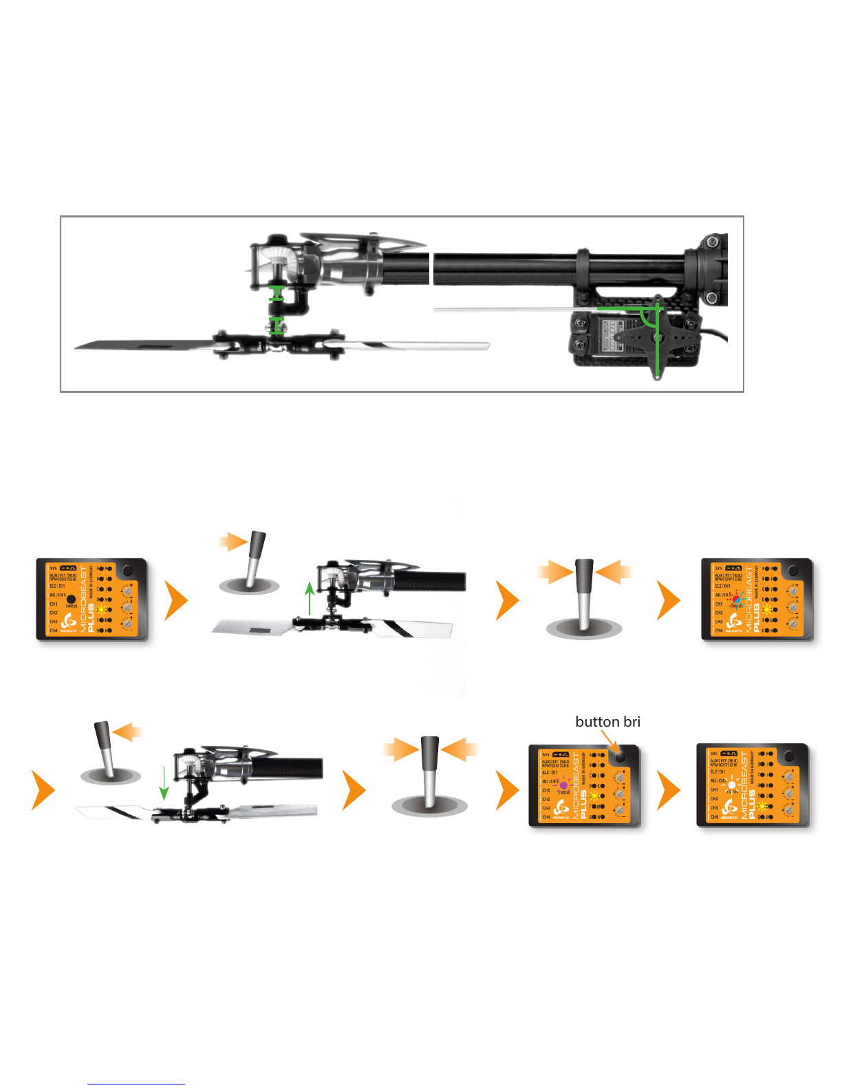
When you‘ve perfectly adjusted the servos now
adjust the linkage rods going from servos to
the swashplate and from the swashplate to the
blade grips. The swashplate must be leveled and
centered on the main shaft and the bladegrips
should be set to 0° of pitch.
Anti-rotation guide leveled
horizontally and twisted
correctly
Swashplate leveled horizontally
0° pitch
Swashplate centered
vertically on main shaft
Status LED o
(= no servo active)
Choose one of the servos connected at
CH1 - CH3 (CH7)
Tap aileron stick
left or right
to choose servo
Move rudder stick to adjust servo
center position
If necessary adjust the swashplate anti-rotation
guide so that the swashplate phasing is not
shifted (only applies to 2-blade rotorheads).
Linkage balls of swashplate
outer ring and blade grips
must be on one line
Setup menu point H- Swashplate servo trim
At SETUP MENU point H we trim the servo center positions so that each servo horn forms an exact 90 degrees angle with the
adjustment linkage. This is necessary as usually you will not be able to attach the servo horns in exact center position to the
servo. After all servos have been trimmed do not proceed to the next menu point yet. With active trimming adjust the linkage
rods according to your helicopter‘s manual.
Initially when the trimming is 0 on all servos the Status LED will be o. Attach the servo horns in center position as good as
possible. By tapping the aileron stick you can select one servo after another. Every color of the Status-LED is corresponding to
a specic servo channel that is indicating its selection by a short up and down move. Use the rudder stick to change the servo
trimming/adjust the center position. You can switch back and forth between the servos as often as you need.
Hint: To reset the servo trims push and hold the button for at least 10 seconds.
CH1
CH2CH3

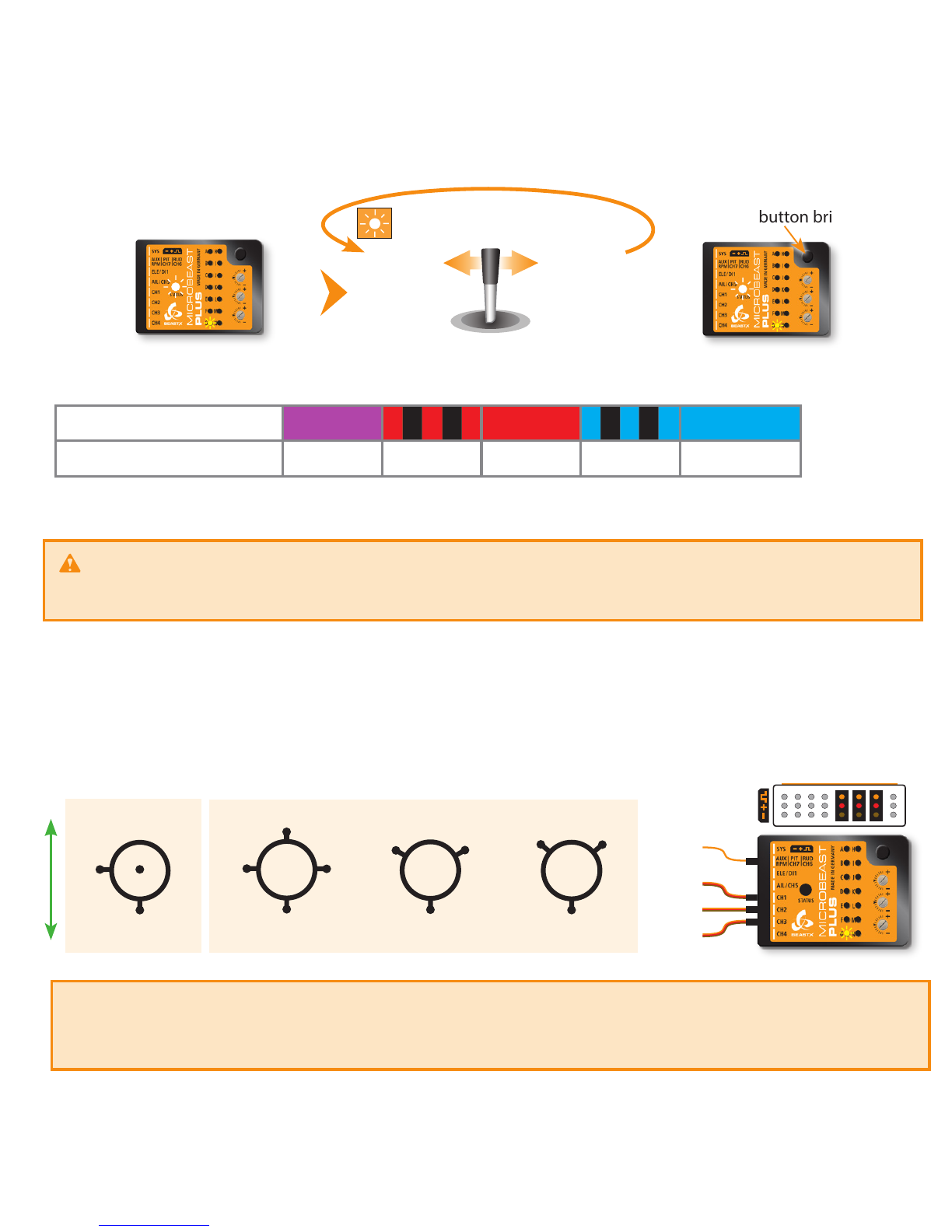
Setup menu point I- Swashplate servo directions
Move the thrust stick and check whether all servos push the swashplate up and down simultaneously. If this is not the case by
tapping the aileron stick you can select one servo after another. Every color of the Status-LED is corresponding to a specic
servo channel that is indicating its selection by a short up and down move. Tap the rudder stick once to change the servo
direction. You can switch back and forth between the servos as often as you need.
After adjusting servo directions make sure that the pitch direction is correct! You can either do this by setting the servo
directions correctly right from the beginning or by changing the direction of the pitch channel in the transmitter later.
Please note: It‘s not possible to reverse the servos with the servo reverse function of your transmitter! The transmitter only controls the
functions of MICROBEAST PLUS, not the servos! Reversing a channel in the transmitter will reverse the control function in total, not the
direction of a single servo (except when using mCCPM swashplate mixing).
Setup menu point H- Swashplate servo trim
At SETUP MENU point H we trim the servo center positions so that each servo horn forms an exact 90 degrees angle with the
adjustment linkage. This is necessary as usually you will not be able to attach the servo horns in exact center position to the
servo. After all servos have been trimmed do not proceed to the next menu point yet. With active trimming adjust the linkage
rods according to your helicopter‘s manual.
Initially when the trimming is 0 on all servos the Status LED will be o. Attach the servo horns in center position as good as
possible. By tapping the aileron stick you can select one servo after another. Every color of the Status-LED is corresponding to
a specic servo channel that is indicating its selection by a short up and down move. Use the rudder stick to change the servo
trimming/adjust the center position. You can switch back and forth between the servos as often as you need.
Setup menu point J- Swashplate servo throw
At SETUP MENU point J we adjust the internal servo throw so that MICROBEAST PLUS has a reference on how far it must move
the servos when controlling the helicopter. To set the throw you have to align one rotorblade on the longitudinal axis (in
parallel to the tail boom) and measure the cyclic pitch with a digital pitch gauge on this rotorblade.
Hint: To reset the servo trims push and hold the button for at least 10 seconds.
Move thrust stick
up and down
Tap aileron stick
left or right
to choose servo
Correct Wrong
Tap rudder stick
left or right
to reverse servo
CH1
CH2CH3

Tap aileron stick to
switch to measure
position
Menu LED Jsolid
Status LED o
Status LED should be solid blue
(see instruction manual for
further details on the LED colors)
Setup menu point K- Collective pitch
3. Now use rudder stick to
adjust maximum positive
collective pitch (i. e. +12°)
0°
+12°
Move thrust stick to
maximum positive pitch
and let it stay there
6°
Use rudder stick to adjust
blade pitch to exact
exact +6 or -6 degrees
Status LED blue
Correct
Status LED red
Wrong
Tap aileron stick
once to swap colors
2. The Status LED must light solid, not just flash. If this is not the case, increase the
servo throw/endpoint of the pitch channel in the transmitter just as far so that
the Status LED changes from flashing to solid when the rudder stick reaches
the end position. But do not increase the endpoint too much in the transmitter!
We need an exact match of full stick position and stick end position, the Status LED
should just change from flashing to solid when reaching the end position.
1. Set internal control direction
4. Finally move thrust stick to
full negative position and
repeat steps 2. and 3. for the
negative pitch.
Do not change control
direction anymore!

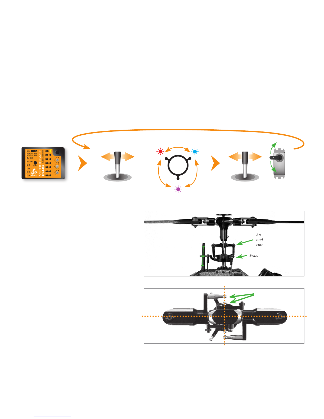
Setup menu point M- Swashplate control directions
Menu LED Lsolid Move thrust, aileron and
elevator sticks carefully to
maximum deection!
Use rudder stick to
adjust the servo limit
Status LED should be solid
blue (see instruction
manual for further details)
Setup menu point L- Swashplate servo limit
You can remove the pitch gauge now! Simultaneously move the sticks for thrust, aileron and elevator to the maximum
deection and check if the servos, swashplate or linkages get jammed in a certain position. By pushing and holding the
rudder stick left or right you can increase or decrease the limit for the servos! Adjust the limit so that the servos just don‘t get
jammed in any possible stick position but don‘t limit the servos more than necessary.
Elevator forward
Aileron to the right Status LED blue
Correct
Status LED red
Wrong
Tap rudder stick
until color is correct Status LED purple
Wrong
There are four possible options, only one is correct!
1. If not already done, move the stick(s) for aileron and elevator on the radio and check whether the swashplate is moved in the correct
directions on the helicopter.The swashplate must follow the stick movement: pushing elevator forward will tilt the swashplate forwards,
adding aileron to the right will move the swash to the right and so on. If the stick is moving the swashplate into the wrong direction
use the reverse function of your transmitter and reverse the aileron and/or elevator channel to set stick control direction correctly.
2. Now set the internal control direction of the MICROBEAST PLUS gyro

When you‘re using the Headspeed Governor of MICROBEAST PLUS now connect the RPM sensor (i. e. magnetical, optical or
brushless phase sensor) or the wire for RPM signal of your ESC to the white sensorport on the long side. For this you may need
the optional available BXA76401 adapter.
Setup menu point N- Internal Headspeed Governor
This menu point is only accessible if you‘re not using a Standard type receiver! Otherwise pressing the button at menu point
Mwill exit the menu and lead back to operation mode.
Enable the Headspeed Governor function by choosing the type of drive system of your helicopter. If you‘re using the governor
function of the ESC or an external governor or if you want to y without headspeed governing at all, choose „Governor o“.
Status LED shows current RPM
Governor mode
Press button briey
Status LED changes color
(= changing RPM Governor mode)
Move rudder stick
left or right Status LED shows current RPM
Governor mode
Status LED o red blue
N Internal Governor Governor o* electric heli nitro/gas heli
ESC
Speed controller
connected to CH5
Throttle servo
connected to CH5
Magnetical sensor
mounted close to
clutch bell of motor
Other manuals for MICROBEAST PLUS
2
This manual suits for next models
4
Table of contents
Other Beastx Accessories manuals


