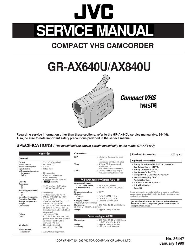
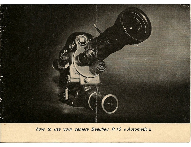
BEAULIEU R 16 Automatic B User manual

Automatic


1
Battery
2
Camera
power
socket
3
Handgrip
for
battery
4
Master
control
switch
5
Release
button
with
cable-release
socket
6
Camera
power-supply
and
safety
switch
7
Footage
counter
8
Frame
counter
9
Frame
counter
zero-reset
knob
10
Single
frame
release
11
Sync
pulse
generator
socket
12
Turret
locking
catch
13
Remote-control
release
socket
3
14
Viewfinder
eyesight
correction
adjustement
15
Filming-speed
control
knob
16
Filming-speed
indicator
window
(tachometer)
17
Speed
range
converter
switch
(24-25
f.p.s.;
2-64
f.p.s.)
18
Film-sensitivity/filming-speed
adjus¬
tement
for
light
meter
19
Reglomatic
automatic
diaphragm
control
20
Reglomatic
cut-out
switch
21
Diaphragm
setting
ring
22
Focal
length
adjustment
ring
23
Focussing
ring
24
Wrist-strap
fixing
nut

PRELIMINARY
DESCRIPTION
1.
Battery.
7
2.
Camera
power
socket.
8
3.
Handgrip
with
built-in
battery
.
9
4.
Master
control
switch.
9
5.
Release
button
with
cable-release
socket.
9
6.
Camera
power-supply
and
safety
switch.
10
7.
Footage
counter.
10
8.
Frame
counter
.
10
9.
Frame
counter
zero-reset
knob.
10
10.
Single
frame
release.
10
11.
Sync
pulse
generator
socket.
11
12.
Turret
locking
catch
.
11
13.
Remote-control
release
socket
.
11
14.
Viewfinder
eyesight
correction
adjustment.
11
15.
Filming-speed
control
knob.
11
16.
Filming-speed
indicator
window
(tachometer).
11
17.
Speed
range
converter
switch
(24-25
f.p.s.;
2-64
f.p.s.)
12
18.
Film-sensitivity/filming-speed
adjustment
for
light
meter
12
19.
Reglomatic
automatic
diaphragm
control.
12
20.
Reglomatic
cut-out
switch.
12
21.
Diaphragm
setting
ring.
13

BEFORE
FILMING
1.
Battery
charge
check.
13
2.
Loading
the
camera
.
13
3.
How
to
hold
the
camera.
15
4.
Adjusting
the
viewfinder.
15
5.
Choice
of
filming
speed.
16
6.
Adjusting
exposure
control
filming-speed/film
sensitivity
17
7.
The
automatic
diaphragm
and
its
use
.
18
8.
Manual
aperture
setting
.
19
9.
Turret-type
cameras.
19
10.
Framing
and
focusing.
20
11.
Unloading
the
camera.
21
SPECIAL
APPLICATIONS
1.
Use
on
a
tripod.
21
2.
Filming
in
reverse.
21
3.
Single-frame
filming.
22
4.
Remote-control
filming
.
22
a)
Mechanical
remote
control
.
b)
Remote
control
by
electric
lead.
c)
Remote
control
by
radio
.
5.
Micro-
and
macrophotography.
23
6.
Sound
synchronization.
24
7.
Using
the
camera
at
very
low
temperatures.
25
5

THE
ACCESSORIES
AND
THEIR
USES
1.
Charging
the
batteries
from
a
wall
socket.
28
2.
Charging
the
batteries
from
a
DC
source
.
28
3.
Use
of
the
200-ft
magazine.
30
MAINTENANCE
1.
Lenses
.
34
2.
Film
gate.
34
3.
Reflex
viewing
system
.
34
4.
Lubrification
.
34
ELECTRICAL
DATA
6

These
instructions
are
intented
for
the
R16
Automatic
(Model
B)
camera,
but
are
perfectly
suitable
for
the
R
16
B
Reflex
Control
Semi-
Automatic
single-lens
or
turret-type
cameras;
special
paragraphs,
applying
exclusively
to
the
types,
are
Included.
To
achieve
the
best
results,
you
should
make
yourself
perfectly
familiar
with
the
camera's
characteristics
and
with
the
possibilities
offered
by
its
various
features.
This
is
why
we
suggest
that
you
should
first
"
get
acquainted
with
your
camera
DESCRIPTION
1.
Battery:
The
R
16
camera
is
powered
by
two
types
of
nickel-cadmium
batteries:
the
500-milliamp
battery,
which
allow
you
to
shoot
seven
100-ft
films
on
a
full
charge,
and
the
1
000-milliamp
battery,
which
will
give
power
for
sixteen
100-ft
films,
at
24/25
f.p.s.
(1).
7

Number
of
100-ft
reels
which
can
be
exposed,
according
to
battery
type
and
filming
speed.
Type
of
battery
Number
of
100-ft
reels
at
64
f.p.s.
at
2
f.p.s.
at
24/25
f.p.s.
500-milliamp'
1
7
14
1000-milliamp
2
16
32
If
200-ft
reels
are
used,
divide
the
above
figures
by
2.
Filming
times
will
vary
according
to
reel-length
and
filming
speed.
2
f.p.s.
24/25
f.p.s.
64
f.p.s.
100-ft
reels
32'
2'30"
1
'
200-ft
reels
65'
5'
2'
Current
consumption
drops
by
about
50
%
between
maximum
and
mini¬
mum
filming
speeds.
But,
on
account
of
the
increase
in
running-time,
the
number
of
reels
exposed
at
2
f.p.s.
is
less
than
at
64
f.p.s.
2.
Camera
power
input
socket
This
connects
the
power
supply
to
the
camera,
whether
the
batteries
are
housed
in
the
camera
handgrip
or
external
to
the
camera.
8

(
I
3.
H
a
ndg
r
i
p
with
built-in
battery
This
handgrip
will
take
two
types
of
batteries
(500
and
1000
milliamp)
with
a
screw-in
connection.
It
comprises
the
camera
power-supply
and
safety
switch.
Other
batteries
are
available
for
special
applications.
4.
M
a
s
t
e
r
control
switch
The
master
switch
has
four
positions
(2)
:
--
at
"
Stop
",
the
camera
is
switched
off;
—
at
"
Normal
",
the
camera
is
ready
for
forward
filming;
—
at
"
Retour
",
the
camera
is
ready
for
reverse
filming;
—
at
"
Control
",
battery
tension
can
be
checked
(providing
the
camera
power-supply
switch
is
depressed,
i.e.
"on
").
5.
R
e
l
e
a
s
e
button
and
cable-release
socket
The
release
button
has
two
positions
(3)
:
—
"
pushed
in
":
this
sets
the
film
running;
—
"
pushed
in
"
and
button
turned
clockwise
through
90°:
this
posi¬
tion
allows
continuous
filming.
When
the
button
is
released,
the
camera
automatically
stops
with
the
image
visible
in
the
view
finder
(i.e.
shutter
closed).
In
the
centre
of
the
button
is
a
threaded
socket
for
fitting
the
cable
release.
9

6.
Camera
power-supply
and
safety
switch
This
switch
has
three
position
(
4
)
:
—
"Off
"
position
no
power
reaches
the
camera
(button
out);
—
On
"
position:
when
the
handgrip
is
held,
the
switch
is
depressed
anci
the
camera
is
ready
to
operate.
—
'
Continuous
''
position;
the
switch
is
depressed
and
turned
clock-
\n\s^
through
90”
with
a
coin.
This
position
is
only
used
when
the
camera
is
mounted
on
a
tripod,
for
remote-control
filming,
and
for
single-frame
filming.
(Never
leave
the
switch
in
this
position,
for
the
baitery
would
be
flat
within
6
hours).
The
camera's
operation
is
nevertheless
controlled
by
the
master
switch
and
the
release
button.
7.
Footage
counter:
The
footage
counter
shows,
in
meters
on
the
upper
scale
and
in
feet
on
the
lower
scale,
the
length
of
film
already
exposed.
This
counter
automatically
returns
to
zero
on
loading
the
camera
(
5
)
.
8
and
9.
Frame
counter
and
zero-reset
knob
The
frame
counter
is
graduated
from
0
to
100.
A
milled
knob
is
provided
for
zero
reset
(6-7).
10.
Single-frame
release:
Single-frame
filming
is
performed
by
means
of
a
cable
release
screwed
into
the
single
frame
release
socket
(each
time
you
wish
to
expose
a
frame,
depress
the
cable
release
button,
with
master
switch
set
to
normal
and
handgrip
power-supply
switch
"
on
").
10

11.
Sync
pulse
generator
socket:
This
allows
a
50-cycle,
25
f.p.s.
or
60
cycle,
24
f.p.s.
sync
pulse
gene¬
rator
to
be
fitted
for
lip-sync
double
system
sound
filming.
12.
Turret
locking
catch:
This
catch
is
found
on
all
the
cameras,
but
is
only
used
on
the
three-
lens
turret
model.
13.
R
e
m
o
t
e
control
socket:
This
socket
takes
a
remote
cable
release
.
14.
Viewfinder
eyesight-correction
adjustment:
The
eyepiece
can
be
set
so
as
to
be
perfectly
adapted
to
the
operator's
eyesight.
15.
Filming-speed
control
knob:
Sets
the
camera
to
the
desired
filming
speed
(8).
16.
Filming-speed
indicator
window-(tachometer)
Its
needle
provides
a
visual
check,
on
the
graduated
scale,
of
precise
filming
speed
(the
line
of
sight
must
be
strictly
perpendicular
to
the
dial).
The
two
upper
dots
give
24
(green
dot)
and
25
f.p.s.
(red
dot)
for
syn¬
chronous
filming,
when
the
filming-speed,
range
switch
is
set
to
24/25
f.p.s.).
This
tachometer
allows
high-accuracy
speed
setting
when
using
a
sync
pulse
generator
for
sound
filming.
With
the
switch
in
the
2-64
f.p.s.
position,
the
lower
scale
indicates
speeds
between
8
and
64
f.p.s.
(9).
11

17.
Speed-range
converter
switch
(2^l2b
f.p.s.
or
2-64
f.p.s.):
When
switched
to
the
left,
the
available
speed
range
is
from
2
to
64
f.p.s.
When
switched
to
the
right,
its
purpose
is
to
give
a
perfectly
accurate
definition
of
speeds
of
24
or
25
f.p.s.
This
is
of
course
essential
for
synchronous
sound
filming
(10).
N.B.
The
converter
switch
should,
as
far
as
possible,
only
be
manipulated
when
the
camera
is
not
operating.
18.
Film-sensitivity/
filming-speed
adjustment
poten¬
tiometer
:
This
knob
makes
it
possible
to
set
filming
speed
according
to
the
sensi¬
tivity
of
the
emulsion
of
the
film
loaded.
This
preliminary
setting,
connec¬
ted
with
the
light-metering
system,
ensures
standardized
exposure
(11)
19.
Automatic
diaphragm
control
(Reglomatic)
This
device
ensures
automatic
diaphragm
control
according
to
the
amount
of
light
falling
on
the
cell
through
the
reflex
viewing
system.
Automatic
adjustment
lenses
are
removable.
20.
R
e
g
l
o
m
a
t
i
c
cut-out
switch:
This
is
a
two-position
switch:
-
In
the
"
auto
"
position,
the
diaphragm
is
automatically
controlled
and
thus
adjusts
the
amount
of
light
transmitted
through
the
lens
(12).
—
In
the
"
semi
"
position,
the
automatic
system
is
cut
out
and
the
dia¬
phragm
must
be
set
manually
according
to
the
cell's
indications
(needle
in
the
viewfinder)
(13).
12

21.
Diaphragm
setting
ring:
In
the
"
auto
"
position,
this
ring
is
positioned
by
a
micro-motor
controlled
by
a
transistorized
system
which
translates
the
light
variations
recorded
by
the
reflex
cell.
In
the
"
semi
"
position,
it
must
be
controlled
manually,
according
to
the
reflex
cell's
indications
(variations
in
light
can
be
checked
from
the
needle
visible
in
the
viewfinder).
BEFORE
FILMING
1.
Battery-charge
check:
Before
you
start
filming,
it
is
a
wise
precaution
to
check
battery
charge.
The
voltmeter
being
built
in
with
the
camera,
this
is
easy:
a)
Set
the
master
switch
to
"
Control
"
(14).
b)
Make
sure
the
filming-speed
converter
switch
is
on
"
2-64
f.p.s.
"
(15).
c)
Simultaneously
depress
the
camera
power-supply
switch
and
the
release
button.
The
tachometer
needle
must
swing
into
the
red
zone,
and
stay
there
(wait
for
about
30
seconds).
If
it
drops
into
the
white
zone,
power
supply
is
deficient.
The
battery
therefore
needs
charging
(see
paragraph
1
in
the
chapter
on
the
use
of
accessories).
d)
If
the
battery
is
adequately
charged,
set
the
master
switch
back
to
"
normal
",
or
to
"
stop
"
if
you
do
not
want
to
film
immediately.
2.
Loading
the
camera:
The
camera
should
be
loaded
in
the
shade.
a)
Open
the
camera
side
plate
by
turning
the
catch
as
shown
by
the
arrow.
Remove
the
take-up
reel
delivered
with
the
camera,
faeing
13

1
I
careful
to
push
the
footage
counter
zero
reset
fork
(16)
(see
use
of
this
fork
when
using
a
200-ft
magazine,
p.
00).
Open
the
film
gate
b)
Unwind
about
10"
of
the
film
leader.
Place
the
feed
reel
on
the
feed
spindle,
fitting
it
snugly
on
to
the
square
arbor.
The
film
must
wind
out
from
the
bottom,
in
the
direction
shown
by
the
arrow
c)
Insert
the
film
between
the
upper
feed
spindle
and
the
feed
guide.
Film
perforations
should
automatically
be
positioned
on
the
correspond¬
ing
spindle
teeth.
To
ensure
this,
thread
the
film
in,
pressing
the
edge
gently
down
and
simultaneously
switching
the
camera
on
(17).
Check
that
perforations
are
well
meshed
with
the
feed
sprocket's
teeth
by
gently
pulling
on
the
film.
Thread
the
film,
with
the
appropriate
loops
as
shown
on
the
film
feed
path
on
the
plate,
and
fit
it
into
the
gate.
Close
the
gate
pressure
plate;
if
the
film
is
properly
positioned
the
pressure
plate
should,
on
resuming
its
position,
ensure
perfect
contact
with
the
ga¬
te.
This
should
be
checked
by
gently
moving
the
film
in
the
normal
(forward)
direction.
The
claw
should
then
be
positioned
so
as
to
fit
into
a
perforation.
d)
After
setting
aside
a
sufficient
length
of
film
to
make
up
the
loop
required
after
the
gate,
thread
the
film
between
the
lower
feed
sprocket
and
guide,
and
proceed
as
in
c)
above
to
ensure
proper
seating.
e)
Thread
the
leader
end
into
the
hub
of
the
take-up
spool,
and
take
up
3
or
4
turns.
f)
Lift
the
footage
counter
zero-reset
fork.
Replace
the
take-up
spool
on
its
spindle.
Release
the
fork,
which
should
return
to
its
position
above
the
upper
side
of
the
spool
(18).
Run
a
few
inches
of
film
to
make
certain
that
everything
is
in
order,
that
the
loops
remain
at
the
right
length
and
that
the
feed
sprockets
teeth
are
properly
engaged.
g)
Replace
the
camera
side-plate,
setting
the
locking
catch
to
"
f
(closed).
The
camera
side-plate
can
in
fact
only
be
locked
in
place
if
the
gate
pressure
plate
has
been
properly
positioned.
h)
The
film
can
be
run
until
the
red
area
of
the
footage
counter,
showing
that
all
the
leader
has
run
through
the
gate,
coincides
with
the
vertical
hairline.
14

3.
How
to
hold
the
camera:
When
using
a
battery-handgrip,
the
photograph
opposite
(
1
9
)
shows
how
the
camera
should
be
held.
Using
this
grip,
the
camera
power-
supply
and
safety
switch
is
held
in
the
"
depressed
"
or
"
on
"
position
by
the
thumb.
This
means
that
the
camera
has
power
available
and
is
ready
to
film.
For
forward
filming,
all
you
now
have
to
do
is
to
press
on
the
release
button
(the
master
switch
being
in
the
"
Normal
"
position).
IMPORTANT:
In
no
case
should
the
camera
be
stopped
by
first
releasing
the
camera
power-supply
switch
for
this
interrupts
the
electric
circuit
and
the
shutter
may
stop
in
any
position;
this
might
lead
to
fogged
frames
whereas,
if
the
release
button
is
first
released,
the
camera
stops
with
its
shutter
closed,
thus
avoiding
any
risk
of
fogging.
The
camera
power-supply
switch
can
then
be
released.
This
power-supply
switch
also
acts
as
a
safety
device.
In
the
"
Off
"
position,
i.e.
when
no
pressure
is
applied,
the
camera's
power-supply
is
cut
off.
4.
Adjusting
the
viewfinder:
a)
Bring
the
zoom
system
to
the
"
wide-angle
"
position.
b)
Set
the
focussing
ring
to
infinity.
c)
Set
the
Reglomatic
switch
to
"
semi
".
d)
Set
the
diaphragm
to
maximum
aperture.
e)
View
a
distant
point,
and
turn
the
eyepiece's
milled
ring
until
the
subject
is
perfectly
sharp.
The
viewfinder
is
then
adjusted
to
your
eyesight.
An
operator
usually
wearing
glasses
can
take
them
off,
for
comfort
s
sake,
and
do
all
his
focussing
with
the
naked
eye
once
the
eyepiece
is
adjusted
to
his
own
eyesight
(withing
limits
of
+2
to
—2
diopters)
(
2
0
)
.
15

5.
Choice
of
filming
speed:
With
the
BEAULIEU
R16
camera,
you
can
film
at
any
speed
between
2
and
64
f.p.s.
Normal
use
:
—
Set
the
speed
range
converter
switch
to
the
left-hand
position
(2
to
64
f.p.s.).
-
Set
the
masterswitch
to
"
normal
—
Depress
the
release
button.
—
Turn
the
filming-speed
control
knob
until
the
tachometer
needle
stops
on
the
selected
speed.
This
can
be
done
using
the
trailer
alone.
Speeds
corresponding
to
the
dots
on
the
lower
part
of
the
filming-speed
dial
(reading
from
left
to
right)
are
as
follows:
1st
point
8
f.p.s.
2nd
point
16
f.p.s.
3rd
point
(red)
25
f.p.s.
4rth
point
32
f.p.s.
5th
point
48
f.p.s.
6th
point
(red)
64
f.p.s.
Synchronous
sound
filming
;
To
ensure
perfect
synchronization
between
picture
and
sound,
it
is
vital
that
you
should
film
at
24
or
25
f,p.s.
(according
to
local
mains
frequencies:
24
f.p.s.
with
60-cycle
supply,
25
f.p.s.
with
50-
cycle).
—
Set
the
filming-speed
converter
switch
in
the
right-hand
position
(24/25
f.p.s.).
—
Set
the
master
switch
to
"
normal
—
Depress
the
release
button.
—
Turn
the
filming-speed
control
knob
until
the
tachometer
needle
lies
strictly
on
the
appropriate
dot
on
the
upper
scale
.
16

—
The
left-hand
dot
(green)
indicates
24
f.p.s.,
that
on
the
right
(red)
25
f.p.s.
NOTE:
Never
let
the
camera
run
empty
at
speeds
in
excess
of
32
f.ps
—
The
tachometer
dial
has
no
marks
corresponding
to
2
or
4
f.p.s.
These
speeds'
extreme
slowness
makes
this
check
superfluous.
Table
of
exposure
times
for
different
filming
speeds:
Filming
speed
Exposure
time
in
fractions
in
f.p.s.
of
a
second
2
.
1/5
4
.
1/10
8
.
1/20
16
.
1/40
24/25
.
1/62
32
.
1/80
48
.
1/120
64
.
1/160
6.
Adjusting
exposure
control
(filming-speed/film-
sensitivity):
—
Bring
the
chosen
filming
speed
opposite
the
film
s
A.S
A.
rating
(in
the
photograph
opposite.
(
2
1
)
the
speed
chosen
was
25
f.p.s.
and
the
film's
sensitivity
100
A.S.A.).
It
is
always
possible
to
set
a
film
sensitivity
lying
between
those
marked.
The
interval
between
two
successive
degrees
of
sensitivity
corresponds
to
the
ratio
between
two
successive
apertures.
Intervals
in
the
sensi¬
tivity
scale,
from
one
mark
to
the
next,
are
equal.
Should
you
for
exam¬
ple
wish
to
set
a
sensitivity
of
150
A.S.A.,
all
you
need
do
is
to
set
the
filming-speed
mark
half-way
between
100
and
200
A.S.A.
17

There
is
a
mathematical
relationship
between
emulsion
speed
and
shutter
speed
(the
latter
being
dependent
on
filming
speed).
Thus,
filming
at
16
f.p.s.
with
50-A.S.A.
film
corresponds
to
filming
:
at
32
f.p.s.
with
100-A.S.A.
film,
or
at
8
f.p.s.
with
25
A.S.A.
film,
and
exposure-times
will
be
identical.
CAUTION:
When
filming
under
conditions
of
exceptionally
poor
lighting,
at
very
slow
speeds
(2
or
4
f.p.s.)
it
is
essential
to
use
an
inde-
pedent,
highly
sensitive
light
meter
if
the
film
used
has
a
rating
of
under
20
A.S.A.
Thus,
for
filming-speeds
slower
than
8
f.p.s.,
it
is
necessary
to
use
the
"
semi
"
setting.
The
filming-speed
film-speed
system
is
adjusted
to
give
perfect
results
under
normal
lighting
conditions.
In
case
of
special
lighting
conditions
(against
the
light,
glare,
snow-
or
seascapes)
or
of
desired
special
effects,
this
adjustment
can
be
adapted.
In
order
to
obtain
longer
expo¬
sure,
all
you
need
do
is
set
a
lower
film
sensitivity.
Conversely
in
order
to
achieve
underexposure,
you
must
set
a
higher
film
rating.
For
example,
at
a
filming
speed
of
25
f.p.s.
with
a
100-A.S.A.
film,
in
order
to
increase
exposure
by
half
an
aperture,
you
only
have
to
bring
the
25
f.p.s.
mark
half-way
between
the
50
and
100
A.S.A.
marks
(22).
7.
The
automatic
diaphragm
and
its
use:
a)
Check
that
the
Reglomatic
cut-out
switch
is
set
to
"
auto
".
b)
Switch
on
the
camera
power-supply.
To
achieve
proper
exposure,
the
needle
visible
in
the
viewfinder
must
remain
on
the
vertical
axis
of
the
crosshairs.
Outside
the
tolerance
zone
(see
diagram
opposite),
(23)
lighting
conditions
are
unsuitable
for
filming.
18

If
the
needle
lies
to
the
right
of
this
zone,
there
is
not
enough
light;
therefore,
if
the
subject
allows
it,
use
a
slower
filming
speed.
If
the
needle
lies
to
the
left,
the
light
is
too
strong,
and
a
neutral
grey
filter
should
be
used
in
front
of
the
lens,
or
a
higher
filming
speed
adopted.
The
automatic
camera
can
be
fitted
with
the
following
lenses;
—
Angenieux
17
-68
mm
zoom
f
2.2.
(24)
—
Angenieux
12.5-75
mm
zoom
f
2.2.
(25)
—
Angenieux
12
-120
mm
zoom
f
2.2.
(26)
Although
these
lenses
are
interchangeable,
they
have
to
be
specially
adjusted
for
each
camera.
CAUTION:
The
automatic
camera
will
take
most
16
mm
cine
lenses
with
C
mounts,
and
still-camera
lenses
the
rear
diameter
of
whose
lens-
mount
does
not
exceed
50
mm
in
the
first
60
mm.
Under
such
conditions,
the
camera
can
only
be
used
in
a
semi-automatic
capacity.
It
will
also
take
extension
tubes
and
microscope
adapter
rings.
8.
Manual
aperture
setting:
Whether
using
a
semi-automatic
camera
(single-lens
or
turret-type)
or
a
fully
automatic
one,
all
you
have
to
do
to
set
the
diaphragm
by
hand
is
to
aim
at
the
subject,
and
to
bring
the
needle
visible
in
the
viewfinder
within
the
tolerance
limits
by
operating
the
diaphragm
setting
ring.
The
cell
lying
behind
the
lens,
no
special
corrections
are
required
when
using
extension
tubes
or
filters.
9.
Turret-type
cameras:
BEAULIEU
16-mm
cameras
can
be
fitted
with
a
3-lens
turret.
To
change
the
lenses'
position,
all
you
need
do
is
to
depress
the
turret
19
26

locking
catch,
thus
freeing
it
(27).
To
swivel
the
turret
(either
clockwise
or
antichlockwise),
use
the
three
knobs
fitted
between
the
lenses,
to
avoid
any
risk
of
modifying
their
settings.
Once
the
catch
has
clicked
into
place,
the
lens
chosen
for
filming
is
properly
aligned
(upper
position)
(28).
The
lenses
most
usually
used
to
meet
all
needs
are:
—
a
normal
lens
of
25
mm
focal
length;
—
a
wide-angle
lens
of
10
mm
focal
length;
—
a
telephoto
lens
of
75
mm
focal
length.
All
standard
lenses
with
a
standard
C
mount
and
a
film
plane
distance
of
17.52
mm
can
be
fitted
on
the
turret,
providing
the
rear
portion
of
the
thread,
when
drawn
in
to
a
maximum
(i.e.
when
focussed
on
infinity)
does
not
exceed
3.8
mm
(0.1496
ins).
The
turret-type
camera
can
also
be
fitted
with
a
zoom
lens,
or
with
very
long-focus
telephoto
lenses.
On
account
of
their
weight,
the
turret
should
be
locked.
For
exceptionally
heavy
lenses,
a
turret
reinforcing
plate
is
available
to
avoid
any
risk
of
warping
(29).
Single-lens
R16
cameras
are
usually
fitted
with
a
zoom
lens.
Both
single-lens
and
turret-type
model
B
cameras
can
be
converted
to
auto¬
matic
providing
the
lenses
designed
for
this
purpose
are
used.
10.
Framing
and
focusing:
We
assume
that
the
viewfinder
has
been
adapted
to
the
operator's
eyesight.
This
being
so,
the
subject
to
be
filmed
must
be
sharp
on
the
focussing
screen.
To
achieve
this,
the
lens
focussing
ring
must
be
turned
until
the
subject
comes
into
pin-point
focus.
This
adjustment
should,
whenever
possible,
be
made
with
the
diaphragm
at
maximum
aperture.
If
the
camera
is
fitted
with
a
zoom
lens,
this
adjustment
should
be
made
with
the
zoom
set
to
telephoto.
20
Other manuals for R 16 Automatic B
3
Table of contents
Other BEAULIEU Camcorder manuals
BEAULIEU
BEAULIEU 6008 S Guide

BEAULIEU
BEAULIEU 2008 S Installation and operating instructions
BEAULIEU
BEAULIEU R 16 Automatic B Operating instructions
BEAULIEU
BEAULIEU R8 User manual
BEAULIEU
BEAULIEU 4008 ZM II User manual

BEAULIEU
BEAULIEU R 16 Automatic B User manual

BEAULIEU
BEAULIEU R 16 Automatic B Operating instructions
