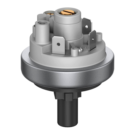
Beck Climair 930.8 Series User manual

Differenzdruckwächter mit einstellbarem
Schaltdruck für die
- Kontrolle von Kühlluftkreisen & Luftströmungen
- Luft- & Brandschutzklappenregelung
- Filter- & Gebläseüberwachung
- Überhitzungskontrolle bei Luftfiltern
Differential Pressure Switch with adjustable
switching pressure for
- Cooling-air circuit & air-flow monitoring
- Air- & fire-protection flaps controlling
- Filter & fan monitoring
- Overheating protection for fan heaters
930.8x Climair®

MONTAGE
INSTALLATION
WICHTIG: Den Druckwächter auf Beschädigungen überprüfen. Bei Beschädigungen nicht verwenden!
Den Druckwächter nicht auf unebenen Flächen befestigen! Die Schrauben nicht zu fest anziehen,
um zu verhindern, dass sich der Gehäuseboden verspannt.
Den Druckwächter mit nach unten gerichteten Druckanschlüssen montieren, damit Kondensat-
feuchtigkeit aus dem Gerät ablaufen kann. Den Druckwächter nur horizontal (elektrische An-
schlüsse zeigen nach oben) montieren, wenn sich kein Kondensat bilden kann. In dieser Position
liegen die Schaltwerte ca. 20 Pa über der Angabe auf der Skala.
IMPORTANT: Check the pressure switch for damages. Do not use if damaged! Do not mount the
pressure switch on uneven surfaces! Do not tighten the screws to much, in order to avoid deform-
ing of the device’s base.
Mount the pressure switch with the pressure connections pointing downwards, to drain conden-
sation moisture which might occur. Mount the pressure switch horizontally (electrical connectors
pointing upwards) only, if no condensate can form. In this position, the switching values are ap-
proximately 20 Pa higher as indicated on the scale.
In der Regel ist die Befestigung mit zwei
nebeneinander liegenden Schrauben aus-
reichend. Der maximale Durchmesser der
Schrauben darf 8 mm nicht überschreiten.
In general, the mounting with two screws
next to each other is sufficient. The maxi-
mum diameter of the screws must not be
bigger than 8 mm.
Metall-Befestigungswinkel S-Form 6402 Metall-Befestigungswinkel L-Form 6401
S-shaped metal mounting bracket 6402 L-shaped metal mounting bracket 6401
60
70
10
40
60
55
18
40
65
65
4,3

Am Einstellknopf mit einem Schraubendreher den ge-
wünschten Druck einstellen, welcher bei steigendem Druck
den Schalter betätigen soll. Bei sinkendem Druck kehrt der
Schalter in seine Ruhelage zurück, sobald die eingestellte
Schaltdifferenz unterschritten wird.
Set the desired pressure, which trips the switch at increasing
pressure, on the setting button using a screwdriver. When
the pressure falls, the switch returns into its resting posi-
tion, as soon as the pressure falls below the set switching
differential.
SCHLAUCHANSCHLUSS
HOSE CONNECTION
WICHTIG: Schläuche beim Anschliessen und Verlegen nicht knicken oder beschädigen. Undichte
Schläuche und Schlauchanschlüsse verursachen Störungen am Gerät oder liefern falsche Messer-
gebnisse. Das an P2 angebrachte Käppchen zur Transportsicherung unbedingt entfernen!
IMPORTANT: Hoses are not allowed to be bend or damaged during mounting. Leaking hoses and
hose connections cause disturbances on the device or inaccurate measurements. It is essential to
remove the cap for transportation safety mounted on P2.
Schlauchinnendurchmesser = 5,5 mm für optimale Klemmung.
Inner hose diameter = 5.5 mm for optimal clamping.
P1 = Überdruckmessung
P1 = Over pressure measurement
P2 = Unterdruckmessung
P2 = Vacuum measurement
P1 & P2 = Differenzdruckmessung
P1 & P2 = Differential pressure measurement
Die Schutzkappe am Druckwächter festschrauben. Die
Anlage erst in Betrieb nehmen, wenn das Gehäuse ge-
schlossen ist. Prüfen des oberen und unteren Schaltpunkts
mittels langsam ansteigendem und sinkendem Druck.
Place the cover and screw it to the pressure switch. Do not
operate the system until the housing is closed. Check the
trip and reset pressure by slowly increasing and decreas-
ing pressure.
SCHALTDRUCK EINSTELLUNG
SWITCHING PRESSURE ADJUSTMENT
ACHTUNG, LEBENSGEFAHR! Unbedingt sicherstellen, dass keine Spannung mehr auf den
elektrischen Anschlüssen anliegt, bevor Einstellungen am Druckwächter vorgenommen werden.
CAUTION, DANGER TO LIFE! Make absolutely sure that no voltage is applied to the electrical
connections, before any settings on the pressure switch are carried out.

ELEKTRISCHER ANSCHLUSS
ELECTRICAL CONNECTION
WARNUNG! Elektrische Anlagen dürfen nur durch autorisierte Elektrofachkräfte errichtet,
erweitert, geändert und in Stand gehalten werden. Arbeiten Sie niemals an elektrischen Anlagen,
wenn Sie nicht selber Fachmann sind! Bei Arbeiten an der Elektrik darf keine Spannung anliegen.
WARNING! Electrical equipment may only be installed, added to, changed or maintained by
authorised electricians. Never work on electrical installations, if you are not a professional! No
voltage must be applied if you work on electrical installations.
Der Schalter (P) im Druckwächter ist als Wechsler ausge-
führt. Pol 3 (COM) schliesst nach Pol 2 (NO) bei stei-
gendem Druck und nach Pol 1 (NC) bei sinkendem Druck.
Die Zuleitung zu Pol 3 (COM), entweder in der Steuerung
oder im Leitungsweg (F), folgendermassen absichern:
The switch (P) in the pressure switch is designed as a
change over contact. Pole 3 (COM) closes to pole 2 (NO)
at increasing pressure and to pole 1 (NC) at decreasing
pressure. Protect the feed line to pole 3 (COM), either in
the control system or along the line (F), as follows:
Max. 1,5 A / 250 VAC, bei ohmschen Verbrauchern.
Max. 1.5 A / 250 VAC, at ohmic consumers.
Max. 0,4 A / 250 VAC, bei induktiven Verbrauchern.
Max. 0.4 A / 250 VAC, at inductive consumers.
Max. 0,1 A / 24 VDC, bei der Schwachstromausführung.
Max. 0.1 A / 24 VDC, at the low-voltage version.
P
3 COM 2 NO
1 NC
F
Die Anschlüsse sind für Quetsch-Kabelschuhe 6,3 mm
ausgelegt. Litzen- und starre Kabel entsprechend konfek-
tionieren.
The connections are intended for 6.3 mm crimp-type-
sockets. Assemble flex- and solid wires accordingly.
Für den elektrischen Anschluss ein dreiadriges Kabel mit
einem Aussendurchmesser von 5-10 mm verwenden. Die
Kabelverschraubung mit einem Drehmoment von 2,5 Nm
anziehen.
Use a three-wired cable with an outer diameter of 5-10
mm for the electrical connection. Tighten the screwed
cable gland with a torque of 2.5 Nm.
1
32

BESTELLMATRIX
ORDER MATRIX
I Druckmessbereiche (Toleranz ±15 %) Schaltdifferenz Bestell-Code
Pressure ranges (Tolerance ±15 %) Switching differential Order code
20 - 300 Pa (0,2 - 3,0 mbar) (0.08 - 1.20 IN W.C.) 10 Pa 0
30 - 400 Pa (0,3 - 4,0 mbar) (0.12 - 1.60 IN W.C.) 15 Pa 4
50 - 500 Pa (0,5 - 5,0 mbar) (0.20 - 2.00 IN W.C.) 20 Pa 3
200 - 1000 Pa (2,0 - 10,0 mbar) (0.80 - 4.00 IN W.C.) 100 Pa 5
500 - 2500 Pa (5,0 - 25,0 mbar) (2.00 -10.00 IN W.C.) 150 Pa 6
1000 - 4000 Pa (10,0 - 40,0 mbar) (4.00 -16.00 IN W.C.) 250 Pa 7
II Schaltkontakte
Switching contacts
für Niederspannung vergoldet, Schraubklemmen beigelegt 1
gold-plated for low voltages, screw terminals enclosed
bis max. 1,5 A (0,4) / 250 VAC, Schraubklemmen beigelegt 2
up to max. 1.5 A (0.4) / 250 VAC, screw terminals enclosed
bis max. 1,5 A (0,4) / 250 VAC, Flachstecker 6,3 x 0,8 mm 3
up to max. 1.5 A (0.4) / 250 VAC, flat plugs 6.3 x 0.8 mm male spade terminals
für Niederspannung vergoldet, Flachstecker 6,3 x 0,8 mm 4
gold-plated for low voltages, flat plugs 6.3 x 0.8 mm male spade terminals
III Befestigung
Fitting method
Montage mit Befestigungsaugen, Via four integral mounting lugs 2
IV Einstellrad
Adjustment knob
Skalierung in mbar, Scale in mbar 1
Skalierung in Pascal, Scale in Pascal 2
Skalierung in Pascal und IN W.C., Scale in Pascal and IN W.C. 3
V IP Schutzart
IP protection category
IP 54 mit Hutmutterverschraubung M16, IP 54 with cap nut conduit M16 5
IP 54 mit Kabeldurchführung M20x1,5, IP 54 with cable conduit M20x1.5 2
IP 54 mit Kabeldurchführung NPT1/2“, IP 54 with cable conduit NPT1/2” 3
IP 00 ohne Schutzkappe, IP 00 without cover 4
VI Verpackung
Packaging
Sammelverpackung, 45 Stk. je Karton, bulk packed, 45 pcs. per carton 1
Sammelverpackung, Faltschachteln beigelegt, bulk packed, folding boxes enclosed 2
Einzelverpackung, individually boxed 3
930.8 X X 2 X X X X
IIIIII IV VVI VII
ABMESSUNG
DIMENSIONS
ENTSORGUNG
DISPOSAL

VII Zubehör Bestell-Code
Accessories Order code
ohne Zubehör, without accessories 1
inkl. Metall-Befestigungswinkel S-Form 6402, with S-shaped metal mounting bracket 6402
2
inkl. Metall-Befestigungswinkel L-Form 6401, with L-shaped metal mounting bracket 6401 3
inkl. Climaset® 6555, with Climaset®6555 4
inkl. Climaset® 6550, with Climaset®6550 5
inkl. Befestigung 6402 und Climaset® 6555, with bracket 6402 and Climaset®6555 6
inkl. Befestigung 6402 und Climaset® 6550, with bracket 6402 and Climaset®6550 7
inkl. Befestigung 6401 und Climaset® 6555, with bracket 6401 and Climaset®6555 8
inkl. Befestigung 6401 und Climaset® 6550, with bracket 6401 and Climaset®6550 9
inkl. Schnell-Befestigung S-Form 6482, with S-shaped snap-on plastic bracket 6482 A
inkl. Schnell-Befestigung L-Form 6481, with L-shaped snap-on plastic bracket 6481 B
inkl. Befestigung 6482 und Climaset® 6555, with bracket 6482 and Climaset®6555 C
inkl. Befestigung 6482 und Climaset® 6550, with bracket 6482 and Climaset®6550 D
inkl. Befestigung 6481 und Climaset® 6555, with bracket 6481 and Climaset®6555 E
inkl. Befestigung 6481 und Climaset® 6550, with bracket 6481 and Climaset®6550 F
ZUBEHÖR
ACCESSORIES
Climaset®bestehend aus 2 m PVC-Schlauch und 2 Kunststoffnippeln 6555
Climaset®consisting of 2 m PVC tubing and 2 plastic tubes
Climaset®bestehend aus 2 m Silikon-Schlauch und 2 Kunststoffnippeln 6557
Climaset®consisting of 2 m silicon tubing and 2 plastic tubes
Climaset®bestehend aus 2 m PVC-Schlauch und 2 abgewinkelten Metallröhrchen 6550
Climaset®consisting of 2 m PVC tubing and 2 angled metal tubes
Climaset®bestehend aus 2 m Silikon-Schlauch und 2 abgewinkelten Metallröhrchen 6556
Climaset®consisting of 2 m silicon tubing and 2 angled metal tubes
Kanalanschlussnippel für Climaset®6555 6551
Duct connecting pipe for Climaset®6555
Abgewinkeltes Metallrohr für Climaset®6550 6552
Angled metal pipe for Climaset®6550
Gummitülle für Metallrohr Climaset®6550 6553
Rubber grommet for Climaset®6550
Rolle mit 100 m PVC-Schlauch 6424
Roll with 100 m PVC tubing
Rolle mit 100 m Silikon-Schlauch 6425
Roll with 100 m silicon tubing
Artikel-Nr.
Article No.

TECHNISCHE DATEN
TECHNICAL DATA
SICHERHEIT & PRODUKTHAFTUNG
SAFETY & LIABILITY
Die geltenden Sicherheitsbestimmungen, Verwendungszweck und technischen Daten sind un-
bedingt einzuhalten. Gemäss diesen Bestimmungen müssen Anlagen spannungsfrei geschaltet
und vor unbeabsichtigtem Wiedereinschalten gesichert werden. Das Produkt darf nicht für U.S.
FDA kontrollierte Anwendungsbereiche verwendet werden. Für Schäden, die durch unsachge-
mässe Verwendung entstehen, wird keine Haftung übernommen.
The existing safety regulations, the intended use and the technical data must be strictly ob-
served. According to these regulations, plants must be zero-potential and secured against
inadvertently restart. The product can not be used for U.S. FDA-controlled application areas.
For damage caused by improper use no liability is assumed.
Medium / Max. Betriebsüberdruck
Medium / Max. operating pressure
Temperaturbereich
Temperature range
Druckanschlüsse
Pressure connectors
Gewicht
Weight
Lebensdauer
Working life
Elektrische Schaltleistung
Electrical rating
Kontaktanordnung
Arrangement of contacts
Schutzarten
Protection category
Luft / 10 KPa für alle Druckbereiche
Air / 10 KPa for all pressure ranges
Mediums- und Umgebungstemperatur: -20 °C bis +85 °C
Lagertemperatur: -40 °C bis +85 °C
Medium and ambient temperature: -20 °C to +85 °C
Storage temperature: -40 °C bis +85 °C
P1 (+): Anschluss an höheren Druck
P2 (–): Anschluss an niedrigeren Druck
P1 (+): Connection to higher pressure
P2 (–): Connection to lower pressure
Mit / ohne Schutzkappe: 160 gr / 115 gr
With / without cover: 160 gr / 115 gr
Mechanisch mehr als 106Schaltspiele
Over 106mechanical switching operations
Standardausführung: Max. 1,5 A (0,4 A) / 250 VAC
Schwachstromausführung: Max. 0,1 A / 24 VDC
Schaltzyklen: Max. 6 Zyklen/min
Standard version: Max. 1.5 A (0.4 A) / 250 VAC
Low-voltage version: Max. 0.1 A / 24 VDC
Switching rate: Max. 6 Cycles/min
Ruhekontakt - NC
Arbeitskontakt - NO
Zuleitung - COM
Break contact - NC
Operating contact - NO
Power supply line - COM
Mit / ohne Schutzkappe: IP 54 / IP 00
With / without cover: IP 54 / IP 00

ABMESSUNG
DIMENSIONS
57,5
80
SW20
22
59
18
7,5
85
6
65
65
ENTSORGUNG
DISPOSAL
Die durchgestrichene Mülltonne auf diesem Produkt weist Sie darauf hin, dass das Produkt am
Ende seiner Lebensdauer getrennt vom Hausmüll entsorgt werden muss.
Bitte bringen Sie in Zukunft alle elektrischen oder elektronischen Geräte zu den eingerichteten
kommunalen Sammelstellen in Ihrer Gemeinde.
The crossed out wheeled bin symbol on the product reminds you of your obligation, that when
you dispose of the appliance, it must be separately collected.
Consumers should contact their local authority or retailer for information concerning the correct
disposal of their old appliance.
Beck GmbH
Druckkontrolltechnik
Postfach 11 31
D-71140 Steinenbronn
e-mail sales@beck-sensors.com
http://www.druckschalter.de
Table of contents
Other Beck Switch manuals
Popular Switch manuals by other brands
Allied Telesis
Allied Telesis Rapier Series How-to
Alcatel-Lucent
Alcatel-Lucent OmniSwitch 6800 Series Hardware user's guide
SMC Networks
SMC Networks ISE70-*-L2 series Operation manuals

Alcatel-Lucent
Alcatel-Lucent OmniSwitch 6900 Hardware user's guide

Renkforce
Renkforce T568A operating instructions
Rocstor
Rocstor Y10A270-A1 user manual
