Solar Solve Marine Solasafe User manual

Doc: ELE16PH33A
Page 1
Solar Solve Marine
Installation Instructions
Installation InstructionsInstallation Instructions
Installation Instructions
for
forfor
for
CASSETTE and
CASSETTE andCASSETTE and
CASSETTE and
NON
NONNON
NON-
--
-CAS
CASCAS
CASS
SS
SETTE
ETTEETTE
ETTE
ELECTRIC SCREENS and BLINDS
ELECTRIC SCREENS and BLINDSELECTRIC SCREENS and BLINDS
ELECTRIC SCREENS and BLINDS
SOLASAFE
SOLASAFESOLASAFE
SOLASAFE
®
®®
®
CASSLITE
CASSLITECASSLITE
CASSLITE
®
®®
®
SOLAROLA
SOLAROLASOLAROLA
SOLAROLA
®
®®
®
DIMMLITE
DIMMLITEDIMMLITE
DIMMLITE
®
®®
®
We reserve the right to make any modifications necessary to ensure products comply with customer requirements.
The drawings in these documents are for illustrative purposes and NOT TO SCA E.
Care and Maintenance
Under normal circumstances dusting with a NON-ABRASIVE dry duster is all that is required. Finger
prints, grease and most stubborn marks on film, blackout, lyverscreen and fibreglass fabrics can be
carefully removed with white spirit and a soft cloth, followed by a further wiping over with a soft non-
abrasive cloth dipped in clean soapy water.
If any type of film or fabric becomes very dirty it can be
carefully wiped over with a soft non-abrasive cloth and clean water with a little soap or detergent. This
will do no harm as long as the film / fabric is allowed to dry completely before being rolled up. Excess
water should be removed as it will leave a water mark when dry.
LEASE NOTE:
IF WINDOWS ARE SLO ING IT
WILL BE NECESSARY TO USE THE
CABLE SU ORT SYSTEM
IM ORTANT NOTE FOR INSTALLER:
LEASE LEAVE THIS INSTRUCTION
SHEET WITH THE ROLLER SCREEN /
BLIND FOR CUSTOMERS REFERENCE
ONLY A FULLY QUALIFIED ELECTRICIAN SHOULD INSTALL MOTORISED
SCREENS / BLINDS FOR HEALTH & SAFETY REASONS AND TO
MAINTAIN
A FULLY VALID WARRANTY

Doc: ELE16PH33A
Page 2
FITTING INSTRUCTIONS FOR INSTALLING
ELECTRICALLY OPERATED CASSETTE MOUNTED
BLINDS AND SCREENS
For 220 - 240 Volt 50/ 60Hz
80 Watt Mains Motors and
24 Volt Low Voltage Motors
10 mm
OPTIONAL CABLE SUPPORT SYSTEM
COMPLETED
CABLE SYSTEM
AS SEEN FROM
BEHIND SCREEN
CASSETTE INSTALLATION
TOP
FIX
FACE
FIX
ALTERNATIVE METHODS
FOR UNI-FIX BRACKET
INSTALLATION
Decide
EXACTLY
where the screen / blind is to be
fitted, ensuring that:-
•The screen / blind will not interfere with
the window stays or any other
obstructions, when operated.
•The screen is absolutely level.
FITTING INSTRUCTIONS FOR INSTALLING ELECTRICALLY
OPERATED NON - CASSETTE MOUNTED BLINDS AND SCREENS
FACE FIX MOTOR
BRACKET
TOP FIX MOTOR
BRACKET
FACE FIX PIN END
BRACKET
TOP FIX PIN END
BRACKET
NON
-
CASSETTE
CABLE
SUPPORT
SYSTEM
1) The brackets supplied are UNI-FIX and are suited to all methods of fitting
including TOP fix, FACE fix and SIDE FIX.
2) Decide EXACTLY where the screen / blind is to be fitted. Ensure that:-
a) The screen / blind will not interfere with the window stays or
any other obstructions, when operated.
b) The screen is absolutely level.
3) Mark off the screw holes and fit the brackets using the self tap screws
provided.
4) Complete the installation by wiring up to the switch and then the power
supply by referring to the wiring diagram.
TOP FIX BRACKETS

Doc: ELE16PH33A
Page 3
MOTOR STOP ADJUSTMENT INSTRUCTIONS
P EASE NOTE THAT THE DROP HAS A READY BEEN PRE-SET TO THE REQUIRED DIMENSION.
THESE INSTRUCTIONS ARE TO MAKE
ADJUSTMENTS
ADJUSTMENTSADJUSTMENTS
ADJUSTMENTS
ON Y.
220 - 240 Volt 50/ 60Hz 80 Watt
Insert the hex-key supplied, into the relevant hex socket. Turn the key in the direction of the +
to increase the rotation of the roll tube or in the direction of -to reduce the number of times
the roll tube rotates.
Low Voltage - 24 Volt DC Motors
'STOP' POSITION
AT TOP
'STOP' POSITION
AT BOTTOM
ADJUST THE 'STOP' POSITIONS
USING THE SUPPLIED HEX-KEY. IF
THE MOTOR IS FITTED TO THE R/H
SIDE THE SAME ADJUSTERS SET THE
SAME 'STOP' POSITIONS
STOP
POSITION
ADJUSTERS
THE STOP POSITION ADJUSTERS
HAVE ARROW SHAPES TO SHOW
THE DIRECTION THEY CONTROL
MOTOR IS SHOWN IN POSITION USING A
FACE FIX MOTOR BRACKET WHICH CAN
ALSO BE USED FOR TOP FIXING

Doc: ELE16PH33A
Page 4
ELECTRIC SCREEN SWITCHES
INDIVIDUAL CONTROL
Basic Low Voltage DC
3 Position Rocker Switch.
Other switches can be
used depending on
individual requirements
which include group and
remote control.
Basic Mains Voltage AC
3 Position Hard Wired
Switch. Other switches
can be used depending
on individual
requirements which
include group and remote
control.
AC 3 Position
Hard Wired
Switch
Connections
DC 3 Position
Rocker Switch
Connections
TO CHANGE THE MOTOR DIRECTION
REVERSE THE TWO WIRES.

Doc: ELE16PH33A
Page 5
AC MOTOR GROU CONTROL WITH SWITCH & 4 MOTOR RELAY UNIT
3 & 2 AC MOTOR RELAYS ARE ALSO AVAILABLE

Doc: ELE16PH33A
Page 6
DC MOTOR GROU CONTROL WITH SWITCH & G S 1020 TRANSFORMER
U TO 10 MOTORS CAN BE CONNECTED & CONTROLLED BY ONE G S 1020
AN INFRARED SENSOR CAN ALSO BE ADDED FOR REMOTE CONTROL
SWITCH

Doc: ELE16PH33A
Page 7
AC
MOTOR
INDIVIDUAL
CONTROL WITH
INFRARED SENSOR
& SWITCH
THE IRT 803 REMOTE ALLOWS
GROU
INFRARED
CONTROL
IR3 IR3
SWITCH
SWITCH

Doc: ELE16PH33A
Page 8
DC
MOTOR
GROU
CONTROL WITH
INFRARED SENSOR
SWITCH CAN ALSO BE ADDED SEE AGE 5
IRS 300
INDIVIDUAL
CONTROL WITH
INFRARED
CAN BE ACHIEVED BY USING ONE
IRS 300 SENSOR ER SCREEN & AN ALTERNATIVE 24V DC TRANSFORMER
IRS 300

Doc: ELE16PH33A
Page 9
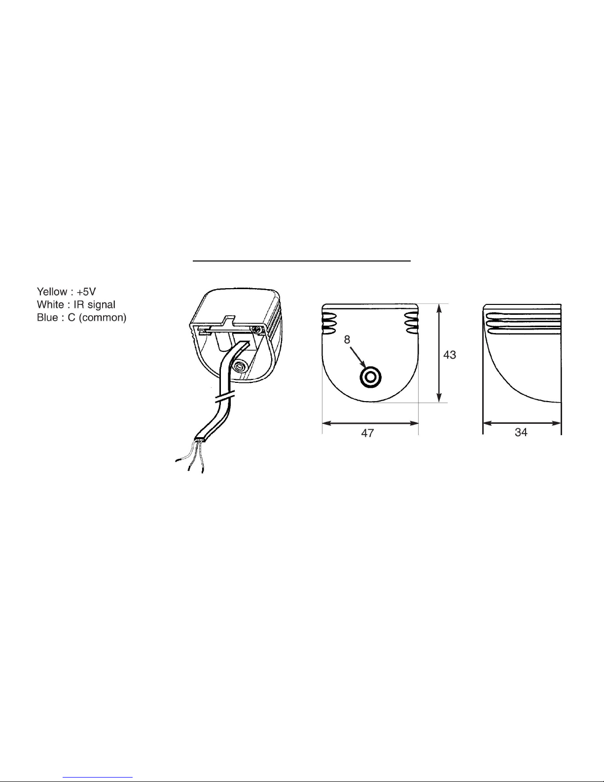
DC IRS 300 INFRARED SENSOR
NOTE: U TO 3 MOTORS CAN BE WIRED TO A SINGLE IRS 300 SENSOR
Doc: ELE16PH33A
Page 10
AC IR3 INFRARED SENSOR
THE IR3 SENSOR IS EQUI ED WITH A FEMALE HONE LUG WHICH ALLOWS THE
EASY CHANGE OF THE CABLE (WITH A HONE LUG)

Doc: ELE16PH33A
Page 11
REMOTE
CONTROLS
If you have ordered a single channel then this will operate any screen or
blind within range. The range of the remote is approximately 7 metres.
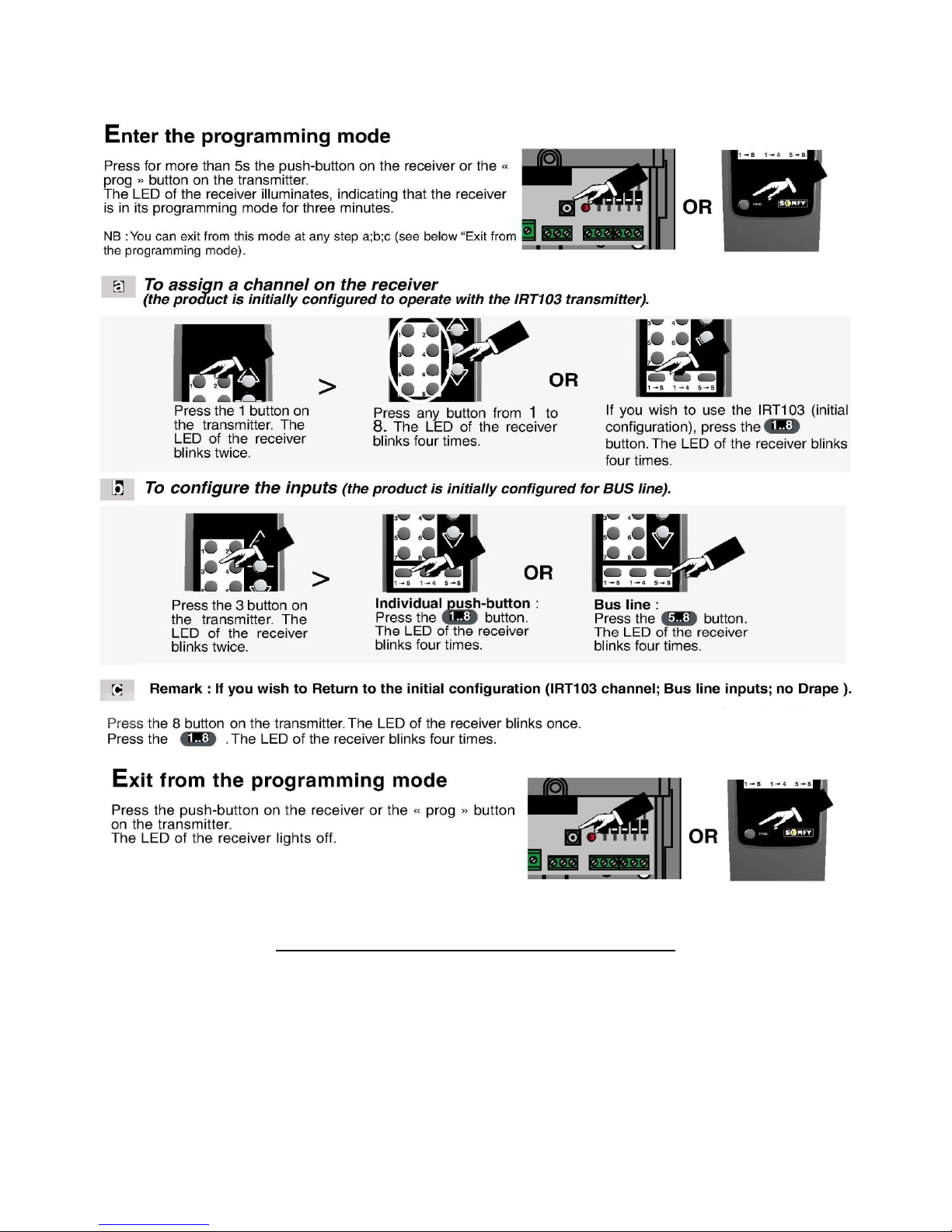
If you have ordered the multi-channel IRT803 remote then please follow the
following programming instructions if the unit has not already been set up.
W
ARNING
:
I
F YOU USE THE
IRT803,
IT IS NECESSARY TO
«
LOCK
»
THE RECEIVERS
THAT ARE NOT BEING ROGRAMMED BY O ERATING THEM IN EITHER
U
OR
DOWN
DIRECTION
(
THEY WILL BE LOCKED FOR
3
MINUTES AND IT IS IM OSSIBLE TO ENTER IN
THE ROGRAMMING MODE BY THE
IRT803).T
O UNLOCK THEM
,
GIVE A
STO
ORDER
.
rogramming the IRT803
IRT103 Remote
IRT803 Remote
Doc: ELE16PH33A
Page 12
FURTHER INFORMATION
More detailed wiring options can be found in each component instructions
which are enclosed in the box. If you have any questions, please contact
the Retailer in the first instance.
This manual suits for next models
3
Table of contents
Popular Switch manuals by other brands


Woosung Automa
Woosung Automa MG100 instruction manual

ANTAIRA
ANTAIRA LMP-0501-M-V2 Quick installation guide

NETGEAR
NETGEAR GS324P installation guide

Extreme Networks
Extreme Networks BlackDiamond X8 Series Hardware installation guide

Altusen
Altusen KN1000 user manual

Cisco
Cisco Nexus 9504 Hardware installation guide


