KTI KGS-2422 User manual

KGS-2422
Managed 24-Port Modular Gigabit Ethernet
Switches with 100BASE-FX Support
Installation Guide
DOC.131212
-1-

(C) 2012-2013 KTI Networks Inc. All rights reserved. No part of this documentation may be reproduced in any
form or by any means or used to make any directive work (such as translation or transformation) without
permission from KTI Networks Inc.
KTI Networks Inc. reserves the right to revise this documentation and to make changes in content from time to
time without obligation on the part of KTI Networks Inc. to provide notification of such revision or change.
For more information, contact:
United States KTI Networks Inc.
P.O. BOX 631008
Houston, Texas 77263-1008
Phone: 713-2663891
Fax: 713-2663893
URL: http://www.ktinet.com/
International Fax: 886-2-26983873
URL: http://www.ktinet.com.tw/
-2-

The information contained in this document is subject to change without prior notice.
Copyright (C) All Rights Reserved.
TRADEMARKS
Ethernet is a registered trademark of Xerox Corp.
FCC NOTICE
This device complies with Part 15 of the FCC Rules. Operation is subject to the following two conditions: (1)
This device may not cause harmful interference, and (2) This device must accept any interference received,
including the interference that may cause undesired operation.
CE NOTICE
Marking by the symbol indicates compliance of this equipment to the EMC directive of the European
Community. Such marking is indicative that this equipment meets or exceeds the following technical
standards:
EMC Class A
EN55022:2006/A1:2007
EN61000-3-2:2006
EN61000-3-3:1995/A1:2001/A2:2005 Class A
EN 55024:1998/A1:2001/A2:2003
IEC 61000-4-2:2001
IEC 61000-4-3:2002/A1:2002
IEC 61000-4-4:2004
IEC 61000-4-5:2001
IEC 61000-4-6:2003
IEC 61000-4-8:2001
IEC 61000-4-11:2001
-3-

-4-
Table of Contents
1. Introduction......................................................................................................................................................5
1.1 Features.................................................................................................................................6
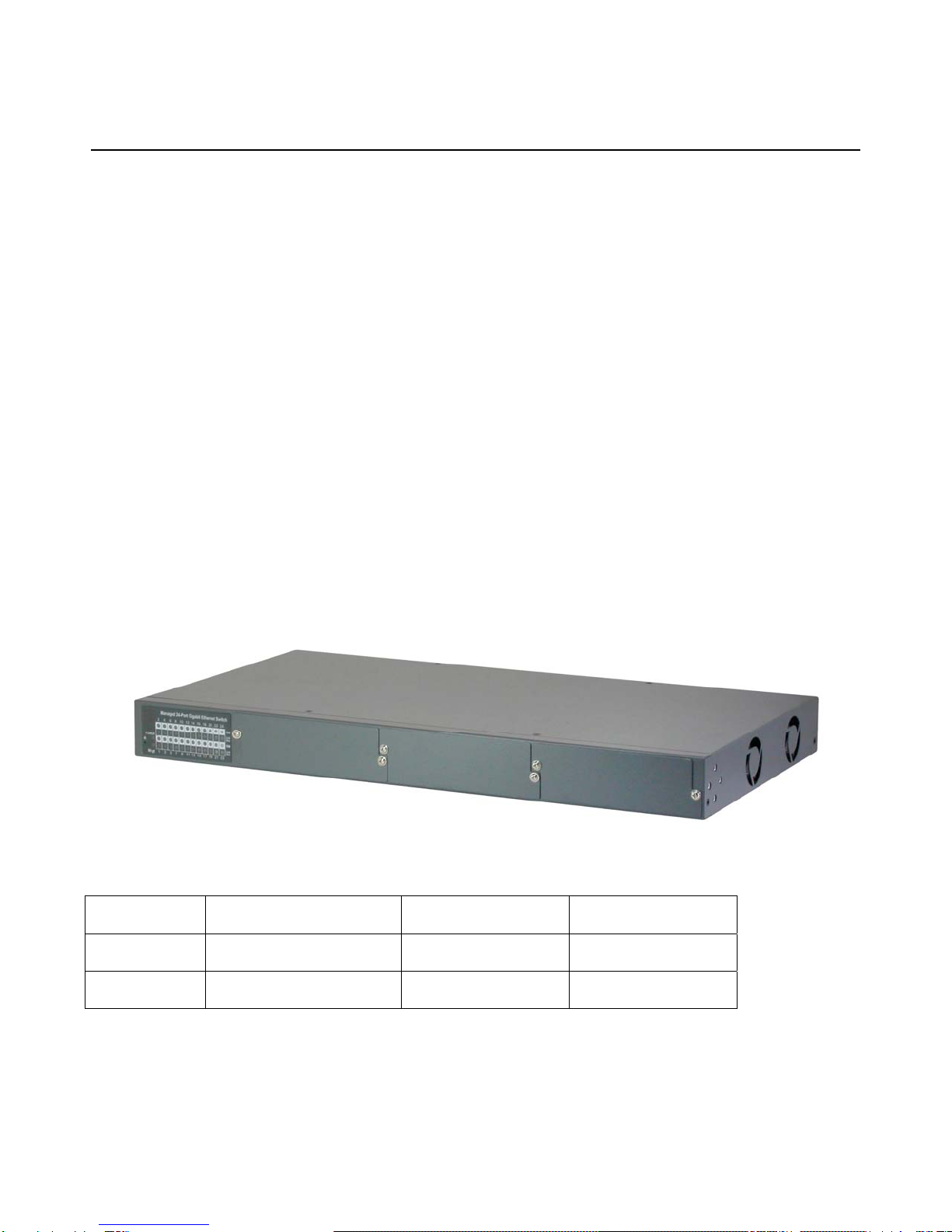
1.2 Product Panels.......................................................................................................................8
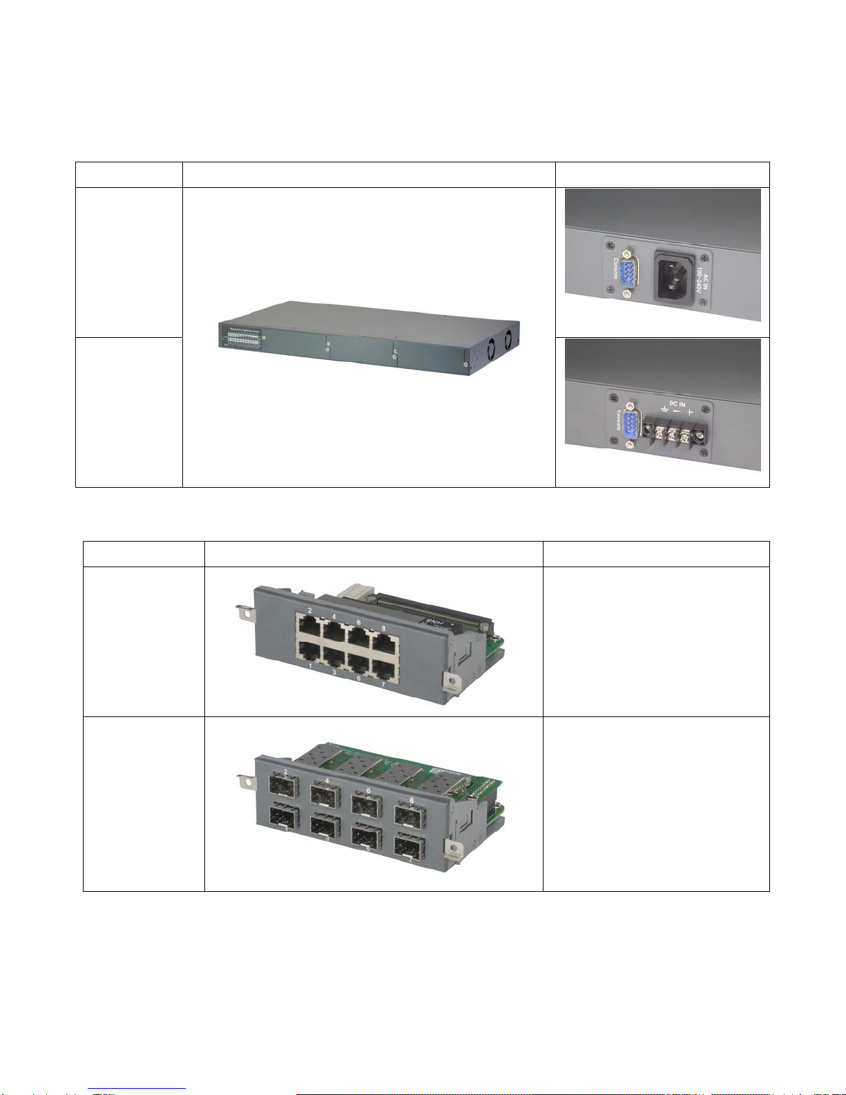
1.3 Optional Modules...................................................................................................................8
1.3.1 Optional Module Table......................................................................................................10
1.4 LED Indicators .....................................................................................................................10
1.5 Specifications.......................................................................................................................11
2. Installation......................................................................................................................................................14
2.1 Unpacking............................................................................................................................14
2.2 Safety Cautions....................................................................................................................14
2.3 Installing Module..................................................................................................................15
2.4 Removing the Module..........................................................................................................16
2.5 Mounting the Switch.............................................................................................................17
2.6 Applying AC Power Supply.................................................................................................. 18
2.7 Applying DC Power Supply.................................................................................................. 19
2.8 Reset Button ........................................................................................................................20
2.9 Making UTP Connections ....................................................................................................20
2.10 Making SFP Fiber Connection........................................................................................... 21
2.11 Making Fixed Duplex Fiber Connection............................................................................. 22
2.12 Making Fixed Bi-Di (Bi-Directional) Fiber Connection........................................................ 23
2.13 LED Indication....................................................................................................................24
2.14 Making Console Connection..............................................................................................25
3. Managing the Switch.....................................................................................................................................26
3.1 IP Address & Password .......................................................................................................26
3.2 Configuring IP Address & Password via Web Interface....................................................... 26
3.3 Configuring IP Address & Password via console and telnet................................................ 29
3.4 Reference Manuals for Web, Console, Telnet Management............................................... 29
3.5 Configuration for SNMP Management................................................................................. 30
3.6 SNMP MIBs .........................................................................................................................31

1. Introduction
The 24-port Managed Gigabit Ethernet Switches are standard L2 switches that meets all IEEE 802.3/u/x/z
Gigabit, Fast Ethernet specifications. The switches provide three 8-port modular slots. Each slot can
accommodate one 8-port module. A variety of modules is available for selection. They include 10/100/1000M
copper module, 100/1000M SFP module, Copper and SFP mixed modules, and Fast Ethernet fiber modules.
Different modules can be installed flexibly in one device rack. The system detects the types of the installed
modules and configures the modules automatically. With variety of modules and flexibility of installation, the
switches can meet most requirements of deployment of fiber networks no matter they are Gigabit Ethernet base,
Fast Ethernet base or even combination of both.
The switches support Telnet CLI, Web GUI, SNMP and console CLI interface for switch stack management.
The network administrator can logon the switch to monitor and configure port operating mode, Quality of
Service, and powerful L2 switching functions such as VLAN, IGMP, RSTP etc. In addition, the switches are
also featured with powerful security functions such as SSH, HTTPS, IEEE 802.1x & MAC-based
authentication, and ACL control to make them suitable for office core applications.
The following figure illustrates the switch has 3 empty slots with no module installed.
Model Definition
Model No. Model Power Input Power connector
KGS-2422-S AC powered model AC 100 ~ 240V IEC320
KGS-2422-D DC powered model DC +/-48V Screw terminals
-5-

-6-
1.1 Features
Fully modular design with three 8-port module slots supporting Gigabit and Fast Ethernet
A variety of optional modules is available for selection including Gigabit copper, Gigabit fiber, Gigabit mix
of copper and fiber, and Fast Ethernet fiber
The copper ports support 10/100/1000Mbps auto-negotiation and auto-MDI/MDI-X detection.
The SFP port can support both 100Mbps fiber transceivers and Gigabit Ethernet SFP fiber transceivers
Support connectivity for Fast Ethernet fiber, 100BASE-FX with SC/ST/BiDi/VF-45 transceivers
Flexible installation with any combination of different modules in one rack
Provides Gigabit full wire speed forwarding
Supports power saving mode when port link down
Supports 802.3x flow control for full-duplex and backpressure for half-duplex
Supports console and in-band Web/Telnet/SSH/HTTPS/SNMP interfaces for switch management
Supports configurable maximum frame length from 1518 up to 9600 jumbo frame
Supports port-based ,802.1Q tag-based VLAN and private VLAN
Provides QoS function
Supports port bandwidth control for ingress and egress
Supports packets storm control function for broadcast, unicast and multicast
Supports MAC address learning, ageing and filtering control
Supports LACP port link aggregation
Supports IEEE 802.1d, 802.1w, 802.1s STP (Spanning Tree Protocol), RSTP, MSTP
Provides port mirroring function
Provides IP Multicasting with IGMP Snooping function
Supports DHCP client for dynamic IP configuration
Supports 802.1X port-based radius authentication for access security
Provides ACL filtering function
Provides port data rate control function
Supports SNTP Client
Supports LLDP
Provides SNMP v1/v2C/v3 agent and event trap function
Supports Configuration download and upload 19” rack mountable
Both AC powered model and DC powered model are available for choice
Management Features:
Port Control
-Port Speed/Duplex Mode/Flow Control/Power saving configuration
-Port frame size control (Jumbo frame support)
QoS
-Traffic Classification up to 4 active priorities

-7-
-Port QoS configuration
-QoS Control List for policy rules
-Port bandwidth control for ingress and egress
-Storm Control for UC, MC and BC
Layer2
-Auto MAC address learning and ageing
-Static MAC address filtering
-Port-based and 802.1Q Tag-based VLAN
-Link Aggregation - LACP
-Rapid Spanning tree - RSTP
-Port Mirroring
-IGMP snooping
-DHCP client for IP configuration
Security features
-Access Control List for L2/L3 protocol filtering, ingress rate limit, port copy
-Port Access Control based on IEEE 802.1X
Management
-Web management
-Console CLI
-Telnet CLI
-Software Download via Web
-SNTP Client
-SNMP v1/v2c Agent
-SSH v2 & HTTPS
-Restore to default configuration
-Configuration download and upload
-System syslog
SNMP MIBs

1.2 Product Panels
The following figure illustrates the front panel and rear panel of the switch:
Model Front Panel Rear Panel (Power Input)
AC powered
model
DC powered
model
1.3 Optional Modules
Module Part No. Image Specifications
8GT 8 10/100/1000 copper ports
8 RJ-45 jacks
8GX 8-port 100/1000 SFP module
8 dual-speed SFP slots
Supports standard 100M or
1000M SFP optical fiber
transceivers
-8-

8G4 4 10/100/1000 copper ports (4
RJ-45) support
10/100/1000Mbps
4 dual-speed SFP slots support
standard 100M or 1000M SFP
optical fiber transceivers
8FX-xxx 8 fixed 100M fiber ports
8 duplex SC transceivers
support 100Mbps
Options: MMF 2km, SMF
20km
8FM-xxx 6 fixed 100M fiber ports with 6
duplex SC transceivers
supporting 100Mbps
2 10/100/1000 copper ports (2
RJ-45)
Fiber options:
MMF 2km, SMF 20km
8FX-T 8 fixed 100M fiber ports
8 duplex ST transceivers
support 100Mbps and MMF
2km
8FM-T 6 fixed 100M fiber ports with 6
duplex ST transceivers
supporting 100Mbps and MMF
2km
2 10/100/1000 copper ports (2
RJ-45)
-9-

8FX-Wxxyy 8 fixed 100M fiber ports
8 BiDi SC transceivers support
100Mbps
Options:
Tx1310/Rx1550 SMF 20km
Tx1550/Rx1310 SMF 20km
8FM-Wxxyy 6 fixed 100M fiber ports with 6
BiDi SC transceivers support
100Mbps
2 10/100/1000 copper ports (2
RJ-45)
Fiber options:
Tx1310/Rx1550 SMF 20km
Tx1550/Rx1310 SMF 20km
1.3.1 Optional Module Table
Module Part No. 10/100/1000M Copper ports 100/1000M pluggable SFP Fixed 100M Fiber
8GT 8 RJ-45
8GX 8 SFP
8G4 4 RJ-45 4 SFP
8FX-T 8 ST for MMF 2km
8FX-C 8 SC for MMF 2km
8FX-SL2 8 SC for SMF 20km
8FX-W3520
8FX-W5320
8 BiDi SC
for single SMF 20km
8FM-SL2 2 RJ-45 6 SC for SMF 20km
8FM-C 2 RJ-45 6 SC for MMF 2km
8FM-T 2 RJ-45 6 ST for MMF 2km
8FM-W3520
8FM-W5320
2 RJ-45 6 BiDi SC
for single SMF 20km
1.4 LED Indicators
LED Function
POWER Power status
Mngt Management status
-10-

-11-
1000M Port speed 1000Mbps status
Link/Act. Port link and activity status (Port 1 – Port 24)
1.5 Specifications
10/100/1000 Copper Ports
Compliance IEEE 802.3 10Base-T, IEEE 802.3u 100Base-TX, IEEE 802.3u 1000Base-T
Connectors Shielded RJ-45 jacks
Pin assignments Auto MDI/MDI-X detection
Configuration Auto-negotiation or software control
Transmission rate 10Mbps, 100Mbps, 1000Mbps
Duplex support Full/Half duplex
Network cable Cat.5 UTP
Dual-speed SFP Slots
Compliance IEEE 802.3z 1000BASE-SX/LX (mini-GBIC)
IEEE 802.3u 100BASE-FX
Connectors SFP slot supports optional both 100M and 1000M SFP type fiber transceivers
Configuration options Auto-negotiation 1000Mbps Full duplex
Forced 100Mbps Full duplex
(Software configurable)
Network cables MMF 50/125m 60/125m, SMF 9/125m
Eye safety IEC 825 compliant
Fixed 100M Fiber Ports
Compliance IEEE 802.3u 100BASE-FX
Connector options Duplex SC for multimode fiber
Duplex SC for single mode fiber
Duplex ST for multimode fiber
BiDi SC for single SM fiber
Configuration 100Mbps, full duplex
Network cables MMF 50/125m 60/125m, SMF 9/125m
Eye safety IEC 825 compliant
Console Port
Interface RS-232, DTE type
Connector 9-pin D-sub

-12-
Switch Functions
MAC Addresses Table 8K entries
Forwarding & filtering Non-blocking, full wire speed
Switching technology Store and forward
Maximum packet length 9600 bytes (Jumbo frame support)
Flow control IEEE 802.3x pause frame base for full duplex operation
Back pressure for half duplex operation
VLAN function Port-based VLAN and IEEE 802.1Q Tag-based VLAN
VLAN support 4096 VLANs (IEEE 802.1Q)
Aggregation LACP Port link aggregation (port trunking)
QoS function Ethernet type, IP-based, DSCP, TOS-based, VID-based, VLAN Tag-based packet
classification
Port rate control, storm control
Port Mirroring Mirror received frames to a sniffer port
AC Power Input (AC powered models)
Interfaces IEC320 receptacle
Operating Input Voltages 100 ~ 240VAC / 0.75‐0.38A
Power Consumption 44W max.
DC Power Input (DC powered models)
Interfaces Screw-type terminal block
Operating Input Voltages +40 ~ +72VDC, -40 ~ -72VDC
Power Consumption 44W max.
Mechanical
Dimension (base) 443 x 245 x 43 mm (WxDxH)
Housing Enclosed metal
Mounting Desktop mounting, 19” rack mounting
Environmental
Operating Temperature Typical -5oC ~ +50oC
Storage Temperature -25oC ~ +85oC
Relative Humidity 10% ~ 90% non-condensing
Electrical Approvals

-13-
FCC Part 15 rule Class A
CE EMC, CISPR22 Class A
Safety LVD, IEC60950-1

-14-
2. Installation
2.1 Unpacking
The product package contains:
The switch unit
One AC power cord (AC powered Model)
One 19” rack mounting kit
One product CD-ROM
2.2 Safety Cautions
To reduce the risk of bodily injury, electrical shock, fire and damage to the product, observe the following
precautions.
Do not service any product except as explained in your system documentation.
Opening or removing covers may expose you to electrical shock.
Only a trained service technician should service components inside these compartments.
If any of the following conditions occur, unplug the product from the electrical outlet and replace the part
or contact your trained service provider:
- The power cable, extension cable, or plug is damaged.
- An object has fallen into the product.
- The product has been exposed to water.
- The product has been dropped or damaged.
- The product does not operate correctly when you follow the operating instructions.
Do not push any objects into the openings of your system. Doing so can cause fire or electric shock by
shorting out interior components.
Operate the product only from the type of external power source indicated on the electrical ratings label. If
you are not sure of the type of power source required, consult your service provider or local power
company.

2.3 Installing Module
The steps to install a module are:
1. Unscrew and open the cover of the module slot.
2. Insert the module into the slot until it is plugged on the slot connector properly.
3. Screw the module on the front panel of the base chassis securely.
-15-

2.4 Removing the Module
The steps to remove an installed module from a base chassis are:
1. Unscrew the module first.
2. Loosen two screw brackets and pull them out as shown below:
3. Use the brackets as handles to pull the module out from the module slot connector.
-16-

4. Remove the module from the slot.
2.5 Mounting the Switch
Desktop Mounting
The switch can be mounted on a desktop or shelf. Make sure that there is proper heat dissipation from and
adequate ventilation around the device. Do not place heavy objects on the device.
Rack Mounting
Two 19-inch rack mounting brackets are supplied with the switch for 19-inch rack mounting.
The steps to mount the switch onto a 19-inch rack are:
1. Turn the power to the switch off.
2. Install two brackets with supplied screws onto the switch as shown in figure below.
After bracket mounting
-17-

2. Mount the switch onto 19-inch rack with rack screws securely.
3. Turn the power to the switch on.
2.6 Applying AC Power Supply
If the purchased switch is with AC power input, one AC power cord which meets the specification of your
country of origin was supplied in package. Before installing AC power cord to the switch, make sure the AC
power is OFF and the AC power to the power cord is turned off.
AC power input specifications
Connector: IEC320 type
Power Rating: 100 ~ 240VAC, 50/60Hz
Voltage Range: 90 ~ 264VAC
-18-

Frequency: 47 ~ 63 Hz
Power Consumption: 44W max.
Important Notes:
1. The socket-outlet shall be installed near the switch and shall be easily accessible.
2. Use of an approved power supply cord not lighter than IEC 60227, H03VV-F, 3G, 0.75mm2 or
alternatively IEC 60245, H05RR-F, 3G, 0.75mm2.
2.7 Applying DC Power Supply
If the purchased switch is with DC power input, the power connector is shown below:
DC power input specifications
Receptacle: Screw-type terminal block
Operating Voltages: +40 ~ +72VDC or -40 ~ -72VDC
Power Consumption: 44W max.
Contacts
Vdc+ input
Vdc- input
Protective earth (Connected chassis and isolated with Vdc+ & Vdc-)
Important Note:
1. For a PERMANENTLY CONNECTED SWITCH EQUIPMENT, a readily accessible power disconnect
device shall be incorporated external to the switch equipment.
2. The power disconnecting device be installed near the switch and shall be easily accessible.
3. The power wiring between the DC power supply and the switch must be stranded copper wire within the
range of 10 to 24 AWG.
-19-

2.8 Reset Button
The reset button is used to perform a reset to the switch. It is not used in normal cases and can be used for
diagnostic purpose. If any network hanging problem is suspected, it is useful to push the button to reset the
switch without turning off the power. Check whether the network is recovered.
The button can also be used to restore the software configuration settings to factory default values. The
operations are:
Operation Function
Press the button during system boot-up and release Restore factory default settings
it after boot-up. The boot-up takes about 17 seconds
and ends with LED diagnostics.
Press the button and release during switch operation Re-boot the switch unit
2.9 Making UTP Connections
The 10/100/1000 RJ-45 copper ports support the following connection types and distances:
Network Cables
10BASE-T: 2-pair UTP Cat. 3, 4, 5, EIA/TIA-568B 100-ohm
100BASE-TX: 2-pair UTP Cat. 5, EIA/TIA-568B 100-ohm
1000BASE-T: 4-pair UTP Cat. 5 or higher (Cat.5e is recommended), EIA/TIA-568B 100-ohm
Link distance: Up to 100 meters
Auto MDI/MDI-X Function
This function allows the port to auto-detect the twisted-pair signals and adapts itself to form a valid MDI to
MDI-X connection with the remote connected device automatically. No matter a straight through cable or
crossover cable are connected, the ports can sense the receiving pair automatically and configure themselves to
match the rule for MDI to MDI-X connection. It simplifies the cable installation.
-20-
Table of contents
Other KTI Switch manuals
Popular Switch manuals by other brands

ABB
ABB Zenith ZTX Series quick start guide

Allied Telesis
Allied Telesis x330 Series installation guide

Pilz
Pilz PSEN ma1.3-08 operating instructions

EMS
EMS fireCell FCX-500-004 installation guide

DIGITECH Audio
DIGITECH Audio AC-1594 user manual

Westinghouse
Westinghouse 30-471 (E) Operation and maintenance manual

Sony
Sony MVS-8000SF user guide

schmersal
schmersal AZM201B-I2-SK-T-1P2PW Operation and assembly instructions

Luxul
Luxul AMS-1208P Quick install guide

Brocade Communications Systems
Brocade Communications Systems FESX624HF installation guide

3Com
3Com Switch 5500G-EI PWR 48-Port Quick reference guide

Aukey
Aukey CB-C76 user manual