rigid fuselage mounting in all aircraft. The VHF transceiver is designed for compliance with RTCA and
EUROCAE airworthiness requirements.
1.3 General description
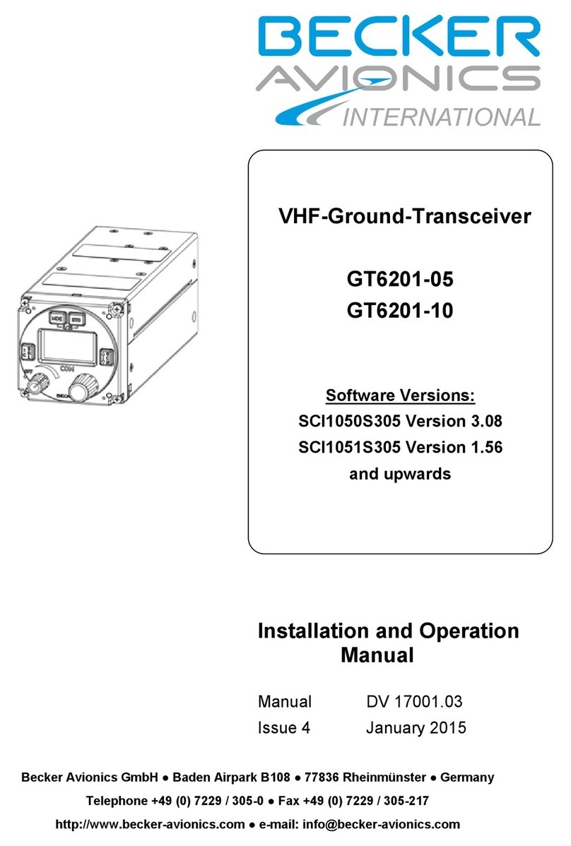
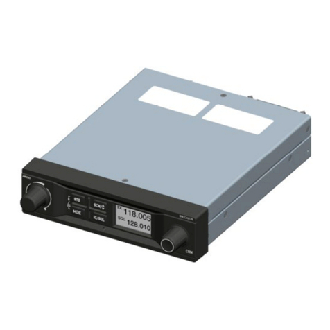
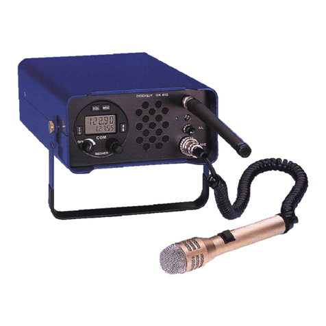
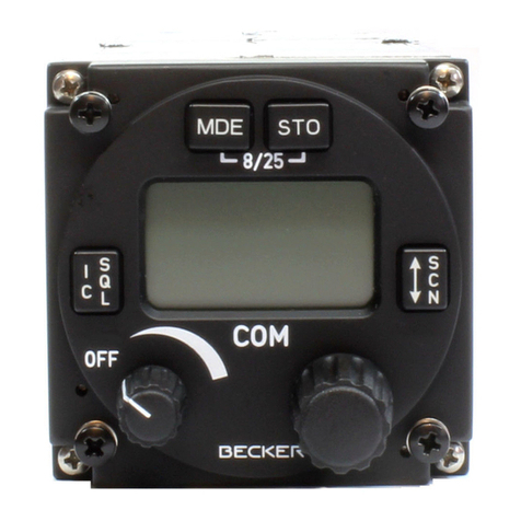
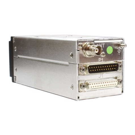
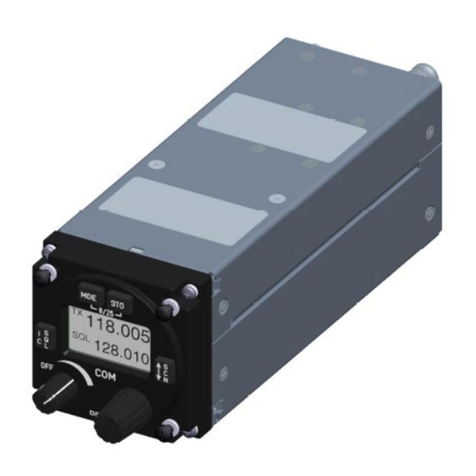
TheVHFtransceiverisdesignedasasingle-blockunitwithdimensionsinkeepingwith58mmdiameter
standard instrument size. Mounting is by means of four screws (behind-panel fitting). AII controls and
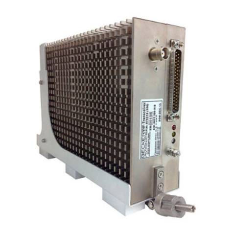
indicators are located on the front panel. The rear panel locates the connector for connecting the
transceiver to aircraft wiring, the antenna socket and a test connector.
The transceiver features a single superhet receiver. A squelch circuit suppresses noise and input
signals below a specific field strength. The switching threshold is adjustable from without through the
case. The squelch can be defeated with the squelch switch.
The transmitter has wideband tuning over the range 118.000 MHz to 136.975 MHz. Transmitter output
power is greater than 5 watt. In transmitter operation sidetone is automatically on. In transceiver with
serial No. of 4000 and above, an arrow flashes on and off in the upper left side of the LCD during
transmission
The injection frequency of the receiver and the transmit frequency of the transmitter are generated by
avoltage-controlledoscillator(VCO)whichissignalledbyadigitalfrequencysynthesizerinconjunction
with a microprocessor.
The microphone input is designed for a dynamic microphone or for a standard microphone, the
transceiver being infactory-set for a dynamic microphone. Conversion to a standard microphone is
done in transceivers up to serial No. 86 by resoldering a jumper on the soldering side of the audio
module. As of serial number No. 86 the conversion is made by reconnecting a wire jumper on the
component side of the audio module. The microphone input is connected to a dynamic compressor
which maintains the modulation depth constant over a microphone input voltage range of approx.
40 dB.
Thefrequencyindicationisaliquidcrystal display(LCD). TheMHzandkHzfrequencyselectors permit
selection of the desired channel frequency. The MHz frequency selector indexes in steps of 1 MHz,
the kHz frequency selector in 25 kHz steps.
The transceiver also contains a memory for storing four different channel frequencies, even when the
transceiver is OFF. The stored frequencies are called up by the channel selector switch in positions
1 - 4. In switch position A a further channel frequency can be set which is, however, lost when the
transceiver is switched off. In transceiver with serial No. fo 4000 or above, the channelfrequency set
in position A is also stored and not deleted when the unit is powerd down.
In addition, when the VHF transceiver is powered up, a self-test function is automatically activated to
test the LCD. For a period of a few secounds, all of the segments in the LCD flash on (188.88).
Aterwards, either the frequency 121.5 MHz appears (channel selector switch in position A), or one of
the 4 stored frequencies (depending on the position of the channel selector switch). The VHF
transceiver is now ready for operation.
In Transceiver with serial No. of 4000 or above, either the most recently set frequency in channelA
appears, or one of four stored frequencies (depending on the position of the channel celector switch).
When the self-test function is activated, an arrow flashes on and off in addition to the digits 188.88
(⇐188.88).
AR 3201 - ( )
Page 1-2 DV 28110.03/.04 Issue 04/92
