Beckoff PS2001-2410-0000 Operator's manual

Documentation | EN
PS2001-2410-0000
Power supply 24 V DC, 10 A, 1-phase
2020-10-08 | Version: 1.0


Table of contents
PS2001-2410-0000 3Version: 1.0
Table of contents
1 Overview.....................................................................................................................................................5
2 Foreword ....................................................................................................................................................6
2.1 Notes on the documentation..............................................................................................................6
2.2 Safety instructions .............................................................................................................................7
2.3 Terminology and abbreviations .........................................................................................................9
3 Technical data, mounting, wiring...........................................................................................................10
3.1 AC input...........................................................................................................................................10
3.2 DC input...........................................................................................................................................12
3.3 Input inrush current..........................................................................................................................13
3.4 Output..............................................................................................................................................14
3.5 Hold-up time ....................................................................................................................................15
3.6 DC-OK relay contact........................................................................................................................16
3.7 Efficiency and losses .......................................................................................................................17
3.8 Lifetime expectancy.........................................................................................................................18
3.9 MTBF...............................................................................................................................................18
3.10 Terminals and wiring .......................................................................................................................19
3.11 Functional wiring diagram................................................................................................................20
3.12 Front side and operating elements ..................................................................................................21
3.13 EMC.................................................................................................................................................22
3.14 Environment ....................................................................................................................................23
3.15 Protective functions .........................................................................................................................24
3.16 Safety features ................................................................................................................................24
3.17 Dielectric strength............................................................................................................................25
3.18 Declaration of conformity and approvals .........................................................................................26
3.19 Dimensions and weight ...................................................................................................................27
4 Application notes.....................................................................................................................................28
4.1 Peak current capability ....................................................................................................................28
4.2 Back-feeding loads ..........................................................................................................................29
4.3 External input protection..................................................................................................................29
4.4 Output circuit breakers ....................................................................................................................29
4.5 Series connection ............................................................................................................................30
4.6 Parallel use to increase power ........................................................................................................31
4.7 Inductive and capacitive loads.........................................................................................................32
4.8 Charging batteries ...........................................................................................................................32
4.9 Operation on two phases.................................................................................................................32
4.10 Use in a tightly sealed enclosure.....................................................................................................32
4.11 Installation positions ........................................................................................................................33
5 Appendix ..................................................................................................................................................35
5.1 Accessories .....................................................................................................................................35
5.2 Documentation issue status ............................................................................................................37
5.3 Support and Service ........................................................................................................................38

Table of contents
PS2001-2410-00004 Version: 1.0
Overview
PS2001-2410-0000 5Version: 1.0
1 Overview
PS2001-2410-0000 | Power supply 24V, 10A, 1 phase, Extra Power
• AC 100-240V wide-range input
• Efficiency of up to 95.2%
• Excellent part-load efficiency
• 120% peak power, 288W
• Safe hiccup overload mode
• Precise triggering of fuses through high overload / peak current
• Active Power Factor Correction (PFC)
• Minimum inrush current surge
• Full output between -25°C and +60°C
• DC-OK relay contact
The power supply PS2001-2410-0000 is a single-phase, 24 V DC power supply with an output current of 10
A and an output power of 240 W.
On the input side, the device features a wide-range input, Active Power Factor Correction (PFC) and inrush
current limiting.
The output operates according to the UI characteristic curve and switches to the safe hiccup mode in case of
overload/short-circuit. The PS2001-2410-0000 features extra power with a continuous maximum output
power of 120% and can precisely trigger fuses with a short peak current.
The power supply unit is part of the PS2000 family and has a width of 39 mm. A DC-OK LED and a potential-
free relay contact monitor the status of the output voltage. Thanks to approvals for the process industry
(ATEX/IECEx), shipbuilding (DNV/GL) and the semiconductor industry (SEMI-F47), the power supply unit
can be used in a wide range of applications.
Overview of technical data *)
Overview of technical data PS2001-2410-0000
Output voltage DC 24V (nominal factory setting 24.1V)
Adjustment range 24 - 28V
Output current 12.0-10.3A (amb. below +45°C)
10.0-8.6A (amb. at +60°C)
7.5-6.5A (amb. at +70°C)
Linear load reduction between +45°C and +70°C
Input voltage AC AC 100-240V -15%/+10%
Mains frequency 50-60Hz ±6%
Input current AC 2.15 / 1.13A at 120 / 230Vac
Input voltage DC DC 110-150V ±20%
Efficiency 93.6 / 95.2% at 120 / 230Vac
Temperature range -25°C to +70°C
Size (W x H x D) 39 x 124 x 117mm (without DIN rail)
Weight 600g
Approvals/markings CE
cULus
Class I Div2
ATEX
IECEx
DNV/GL
SEMI F47
EAC
*) All values typical for 24V, 10A, 230Vac, 50Hz, +25°C ambient temperature and after a warm-up period of five minutes, unless other-
wise stated.

Foreword
PS2001-2410-00006 Version: 1.0
2 Foreword
2.1 Notes on the documentation
Copyright
© Beckhoff Automation GmbH & Co. KG, Germany.
The reproduction, distribution and utilization of this document as well as the communication of its contents to
others without express authorization are prohibited.
Offenders will be held liable for the payment of damages. All rights reserved in the event of the grant of a
patent, utility model or design.
Disclaimer
The documentation has been prepared with care. The products described are, however, constantly under
development.
We reserve the right to revise and change the documentation at any time and without prior announcement.
No claims for the modification of products that have already been supplied may be made on the basis of the
data, diagrams and descriptions in this documentation.
Trademarks
Beckhoff®, TwinCAT®, EtherCAT®, EtherCATG®, EtherCATG10®, EtherCATP®, SafetyoverEtherCAT®,
TwinSAFE®, XFC®, XTS® and XPlanar® are registered trademarks of and licensed by Beckhoff Automation
GmbH. Other designations used in this publication may be trademarks whose use by third parties for their
own purposes could violate the rights of the owners.
Patent Pending
The EtherCAT Technology is covered, including but not limited to the following patent applications and
patents: EP1590927, EP1789857, EP1456722, EP2137893, DE102015105702 with corresponding
applications or registrations in various other countries.
Intended audience
This description is only intended for the use of trained specialists in control and automation engineering who
are familiar with the applicable national standards.
It is essential that the documentation and the following notes and explanations are followed when installing
and commissioning these components.
It is the duty of the technical personnel to use the documentation published at the respective time of each
installation and commissioning.
The responsible staff must ensure that the application or use of the products described satisfy all the
requirements for safety, including all the relevant laws, regulations, guidelines and standards.

Foreword
PS2001-2410-0000 7Version: 1.0
2.2 Safety instructions
Description of instructions
In this documentation the following instructions are used.
These instructions must be read carefully and followed without fail!
DANGER
Serious risk of injury!
Failure to follow this safety instruction directly endangers the life and health of persons.
WARNING
Risk of injury!
Failure to follow this safety instruction endangers the life and health of persons.
CAUTION
Personal injuries!
Failure to follow this safety instruction can lead to injuries to persons.
NOTE
Damage to environment/equipment or data loss
Failure to follow this instruction can lead to environmental damage, equipment damage or data loss.
Tip or pointer
This symbol indicates information that contributes to better understanding.
Intended use
This device is designed for installation in a housing and is intended for general professional use, for example
in industrial control systems or office, communication and measuring equipment.
Do not use this power supply in installations where a malfunction could cause serious injury or danger to
human life.
Exclusion of liability
All the components are supplied in particular hardware and software configurations appropriate for the
application. Modifications to hardware or software configurations other than those described in the
documentation are not permitted, and nullify the liability of Beckhoff Automation GmbH & Co. KG.
Personnel qualification
This description is only intended for trained specialists in control, automation and drive engineering who are
familiar with the applicable national standards.
Safety regulations
Please note the following safety instructions and explanations!
Product-specific safety instructions can be found on following pages or in the areas mounting, wiring,
commissioning etc.

Foreword
PS2001-2410-00008 Version: 1.0
Safety instructions and installation requirements for PS2001-2410-0000 power supply unit
DANGER
Danger of electric shock, fire, injuries, injuries resulting in death!
• Do not use the power supply without proper earthing (protective conductor). Use the terminal at the input
terminal strip for the earth connection, not one of the screws on the housing.
• Switch off the power supply before working on the device. Provide protection against unintentional re-
connection.
• Ensure proper wiring by following all local and national regulations.
• Do not modify or attempt to repair the device.
• Do not open the device, as high voltages are present inside.
• Avoid foreign bodies entering the housing.
• Do not use the device in damp locations or in areas where moisture or condensation is likely to occur.
• Do not touch the device when it is switched on or immediately after it has been switched off. Hot sur-
faces can cause burns.
WARNING
Explosion hazard warning!
Use only in standard vertical mounting orientation with the input terminals at the bottom of the device.
Replacement of components may affect the suitability for this environment.
Do not disconnect the device from the mains and do not operate the voltage adjustment unless the power is
switched off or the environment can be considered safe.
For the end product a suitable housing must be provided, which has a minimum protection class of IP54
and meets the requirements of EN 60079-0.
NOTE
Instructions for use in potentially explosive atmospheres
The device is suitable for use in the following areas:
Class I Division 2 Groups A, B, C, D
and for use in Group II environments of Category 3 (Zone 2).
Classification:
ATEX: EPS 15 ATEX 1 101 X, II 3G EX ec nC IIC T4 Gc / IECEx EPS 20.0046X.
Further notes on installation requirements
• This device contains no parts that require maintenance. If an internal fuse trips, this is due to an
internal defect.
• If any damage or malfunction occurs during installation or operation, turn off the power immedi-
ately and return the device to the factory for inspection.
• Mount the device on a DIN rail so that the input terminals are at the bottom of the device. For
other mounting positions, please refer to the load reduction requirements in this document. See
chapter Installation positions.
• This device is designed for convection cooling and does not require an external fan. Do not ob-
struct the air circulation. No more than 15% of the ventilation grille may be covered (e.g. by cable
ducts)!
• Maintain the following installation distances: 40mm at the top, 20mm at the bottom and 5mm
on the left and right are recommended if the device continuously runs at more than 50% of the
rated output. Increase this distance to 15mm if the adjacent device is a heat source (e.g. an-
other power supply unit).

Foreword
PS2001-2410-0000 9Version: 1.0
2.3 Terminology and abbreviations
PE and the earthing
symbol
PE is the abbreviation for "protective earth" and has the same meaning as the
earthing symbol
Earth, ground This document uses the term “earth” which is the same as the U.S. term “ground”.
T.b.d. Still to be defined, value or description will follow in due course.
AC 230V A value preceded by "AC" or "DC" represents a nominal voltage or a nominal
voltage range. The nominal voltage or the nominal voltage range may be provided
with tolerances. (e.g. AC 230V ±10%). The calculated total range then indicates
the working range of the device.
Example:
DC 12V refers to a 12V battery, regardless of whether it is fully charged
(13.7Vdc) or discharged (10Vdc).
230Vac A value followed by the unit Vac or Vdc is an instantaneous value that does not
contain any additional tolerances.
50Hz vs. 60Hz Unless otherwise specified, AC 100V and AC 230V parameters are valid at a
mains frequency of 50Hz. AC 120V parameters are valid for a mains frequency of
60Hz.
may A keyword indicating a choice without implied preference.
shall A keyword indicating a mandatory requirement.
should A keyword indicating a choice with a clearly preferred method of implementation.

Technical data, mounting, wiring
PS2001-2410-000010 Version: 1.0
3 Technical data, mounting, wiring
3.1 AC input
AC input
AC input Nom. AC 100-240V Suitable for TN, TT and IT networks
AC input range Min. 85-264Vac Continuous operation
Min. 264-300Vac For up to 500ms max.
Permissible voltage L or N to earth Max. 300Vac Continuous according to IEC 62477-1
Input frequency Nom. 50-60Hz ±6%
Turn-on voltage Typ. 80Vac Static, see Fig. Input voltage range; switch-on behavior definitions
Shut-down voltage Typ. 70Vac Static, see Fig. Input voltage range; switch-on behavior definitions
Typ. 55Vac Dynamic value for up to 250ms max.
External input protection See recommendations in chapter External input protection [}29]
AC input AC 100V AC120V AC230V
Input current Typ. 2.60A 2.15A 1.13A At 24V, 10A, see Fig. Input current over out-
put current; power factor over output current
Power factor*) Typ. 0.99 0.99 0.97 At 24V, 10A, see Fig. Input current over out-
put current; power factor over output current
Peak factor**) Typ. 1.5 1.5 1.65 At 24V, 10A
Start-up delay Typ. 300ms 290ms 240ms See Fig. Input voltage range; switch-on behav-
ior definitions
Rise time Typ. 30ms 30ms 30ms At 24V, 10A constant current load, 0mF load
capacity, see Fig. Input voltage range; switch-
on behavior definitions
Typ. 75ms 75ms 75ms At 24V, 10A constant current load, 10mF
load capacity, see Fig. Input voltage range;
switch-on behavior definitions
Turn-on overshoot Max. 200mV 200mV 200mV See Fig. Input voltage range; switch-on behav-
ior definitions
External input protection See recommendations in chapter External input protection [}29]
*) The power factor is the ratio of real (or active) power to apparent power in an AC circuit.
**) The peak factor is the mathematical ratio of the peak value to the RMS value of the input current
waveform.
Fig.1: Input voltage range; switch-on behavior definitions

Technical data, mounting, wiring
PS2001-2410-0000 11Version: 1.0
Fig.2: Input current over output current; power factor over output current

Technical data, mounting, wiring
PS2001-2410-000012 Version: 1.0
3.2 DC input
DC input
DC input Nom. DC 110-150V ±20%
DC input range Min. 88-180Vdc Continuous operation
DC input current Typ. 2.35A at 110Vdc, at 24V, 10A
DC input current Typ. 0.84A at 300Vdc, at 24V, 10A
Permissible voltage L or N
to earth
Max. 375 Vdc Continuous according to IEC 62477-1
Turn-on voltage Typ. 80 Vdc static
Shut-down voltage Typ. 70 Vdc static
Typ. 55 Vdc Dynamic value for up to 250ms max.
Instructions for DC operation
Fig.3: Wiring for DC input
• Use a battery or a comparable DC source. Operation on the DC link of frequency converters is not
recommended and may lead to defects or malfunctions.
• Connect the positive pole to L and the negative pole to N.
• Connect the PE terminal to the protective conductor or machine ground.

Technical data, mounting, wiring
PS2001-2410-0000 13Version: 1.0
3.3 Input inrush current
Active inrush current limitation (NTCs that are bridged by a relay contact) limits the inrush current after the
input voltage is switched on.
The charge current of the interference suppression capacitors during the first few microseconds after
switching on is not taken into account.
AC 100V AC 120V AC 230V
Input inrush
current
Max. 11Apeak 7Apeak 11Apeak At +40°C, cold start
Typ. 9Apeak 6Apeak 6Apeak At +25°C, cold start
Typ. 9Apeak 6Apeak 9Apeak At +40°C, cold start
Inrush energy Max. 0.1A²s 0.1A²s 0.4A²s At +40°C, cold start
Fig.4: Typical switch-on behavior at nominal load, 120Vac input voltage and 25°C ambient temperature
Fig.5: Typical switch-on behavior at nominal load, 230Vac input voltage and 25°C ambient temperature

Technical data, mounting, wiring
PS2001-2410-000014 Version: 1.0
3.4 Output
Output voltage Nom. 24V
Adjustment range Min. 24-28V Guaranteed value
Max. 30.0V This is the maximum output voltage that can occur in the end position of the po-
tentiometer in clockwise direction due to tolerances. It is not a guaranteed
value that can be achieved.
Factory settings Typ. 24.1V ±0.2% at full load (cold device)
Line regulation Max. 10mV Between 85 and 300Vac
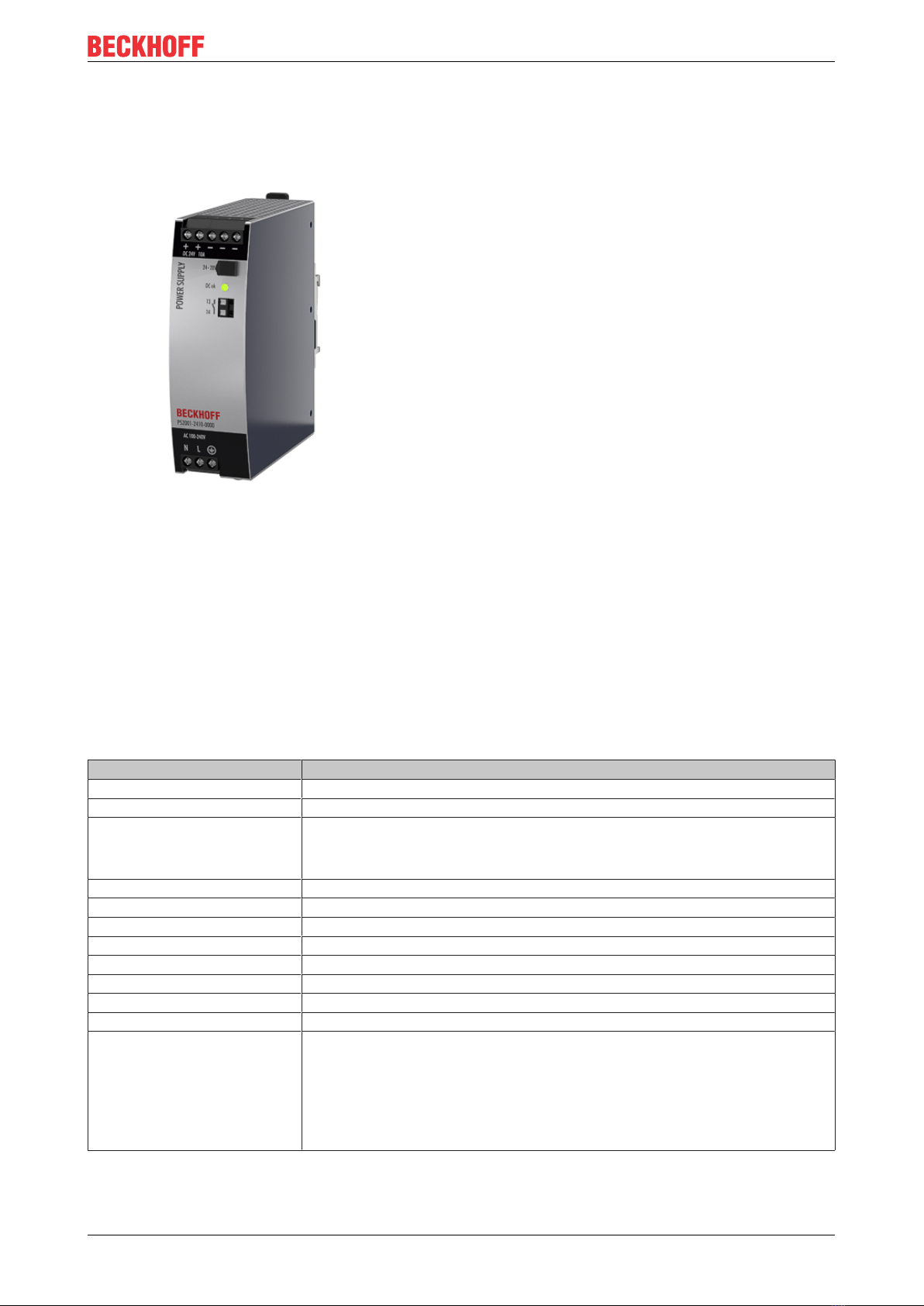
Load regulation Max. 50mV Between 0 and 12A, static value, see Fig. Output voltage over output current,
typ.
Residual ripple and ripple
voltage
Max. 50mVss Bandwidth 20Hz to 20MHz, 50Ohm
Output current Nom. 12A1) At 24V and an ambient temperature below 45°C, see Fig. Output current over
ambient temperature
Nom. 10A At 24V and 60°C ambient temperature, see Fig. Output voltage over output cur-
rent, typ.
Nom. 7.5A At 24V and 70°C ambient temperature, see Fig. Output current over ambient
temperature
Nom. 10.3A1) At 28V and an ambient temperature below 45°C, see Fig. Output current over
ambient temperature
Nom. 8.6A At 28V and 60°C ambient temperature, see Fig. Output voltage over output cur-
rent, typ.
Nom. 6.45A At 28V and 70°C ambient temperature, see Fig. Output current over ambient
temperature
Typ. 30A For at least 12ms once every five seconds, see Fig. Dynamic output current ca-
pacity, typ. The output voltage remains above 20V.
See chapter on Peak current capability [}28] for further peak current mea-
surements. For AC 100V networks the pulse length is shorter than 12ms.
Overload behavior Continuous cur-
rent
Output voltage > 13Vdc, see Fig. Output voltage over output current, typ.
Hiccup mode2) Output voltage < 13Vdc, see Fig. Output voltage over output current, typ.
Short circuit current Min. 12.5A3) Load impedance <45mOhm, see Fig. Short circuit at output, hiccup mode, typ.
Max. 15.5A3) Load impedance <45mOhm, see Fig. Short circuit at output, hiccup mode, typ.
Max. 5A RMS value of current, load impedance 50mOhm, see Fig. Short circuit at out-
put, Hiccup mode, typ.
Min. 28A Up to 12ms, load impedance <45mOhm, see Fig. Dynamic output current ca-
pacity, typ.
Typ. 30.5A Up to 12ms, load impedance <45mOhm, see Fig. Dynamic output current ca-
pacity, typ.
Output capacity Typ. 4 400μF Included in the power supply
1) Extra Power
This continuous power / current is permissible up to an ambient temperature of +45°C. Above +45°C, use
this power / current for a maximum duty cycle of 10%, i.e. no more than 1 minute every 10 minutes.
2) Hiccup mode
In the event of heavy overload (when the output voltage drops below 13V), the power supply provides
continuous output current for 2s. The output is then switched off for about 18 seconds before a new switch-
on attempt is automatically made. This cycle is repeated as long as the overload persists. After the overload
has been rectified, the device will operate normally. See Fig. Short circuit at output, hiccup mode, typ.
3) The discharge current of the output capacitors is not included.
Technical data, mounting, wiring
PS2001-2410-0000 15Version: 1.0
Fig.6: Output voltage over output current, typ.; Dynamic output current capacity, typ.
Fig.7: Short circuit at output, hiccup mode, typ.
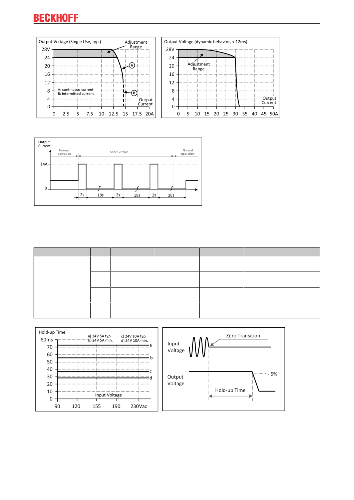
3.5 Hold-up time
AC 100V AC 120V AC 230V
Power failure
Hold-up time
Typ. 73ms 73ms 73ms At 24V, 5A, see Fig. Hold-
up time over input voltage
Min. 55ms 55ms 55ms At 24V, 5A, see Fig. Hold-
up time over input voltage
Typ. 37ms 37ms 37ms At 24V, 10A, see Fig. Hold-
up time over input voltage
Min. 28ms 28ms 28ms At 24V, 10A, see Fig. Hold-
up time over input voltage
Fig.8: Hold-up time over input voltage; switch-off behavior, definitions

Technical data, mounting, wiring
PS2001-2410-000016 Version: 1.0
3.6 DC-OK relay contact
This feature monitors the output voltage at the output terminals of an active power supply.
The contact closes when the output voltage typically reaches 90% of the set output voltage.
The contact opens when the output voltage drops more than 10% below the set output voltage.
Short drops are extended to a signal length of 100ms. Drops that are shorter
than 1ms are ignored.
Switching hysteresis 1 V
Contact load capacity Maximum 60Vdc 0.3A, 30Vdc 1A, 30Vac 0.5A, ohmic load
Minimum permissible load: 1mA at 5Vdc
Insulation voltage See the dielectric strength table in the chapter on Safety features [}24]
Fig.9: Behavior of the DC-OK relay contact
Technical data, mounting, wiring
PS2001-2410-0000 17Version: 1.0
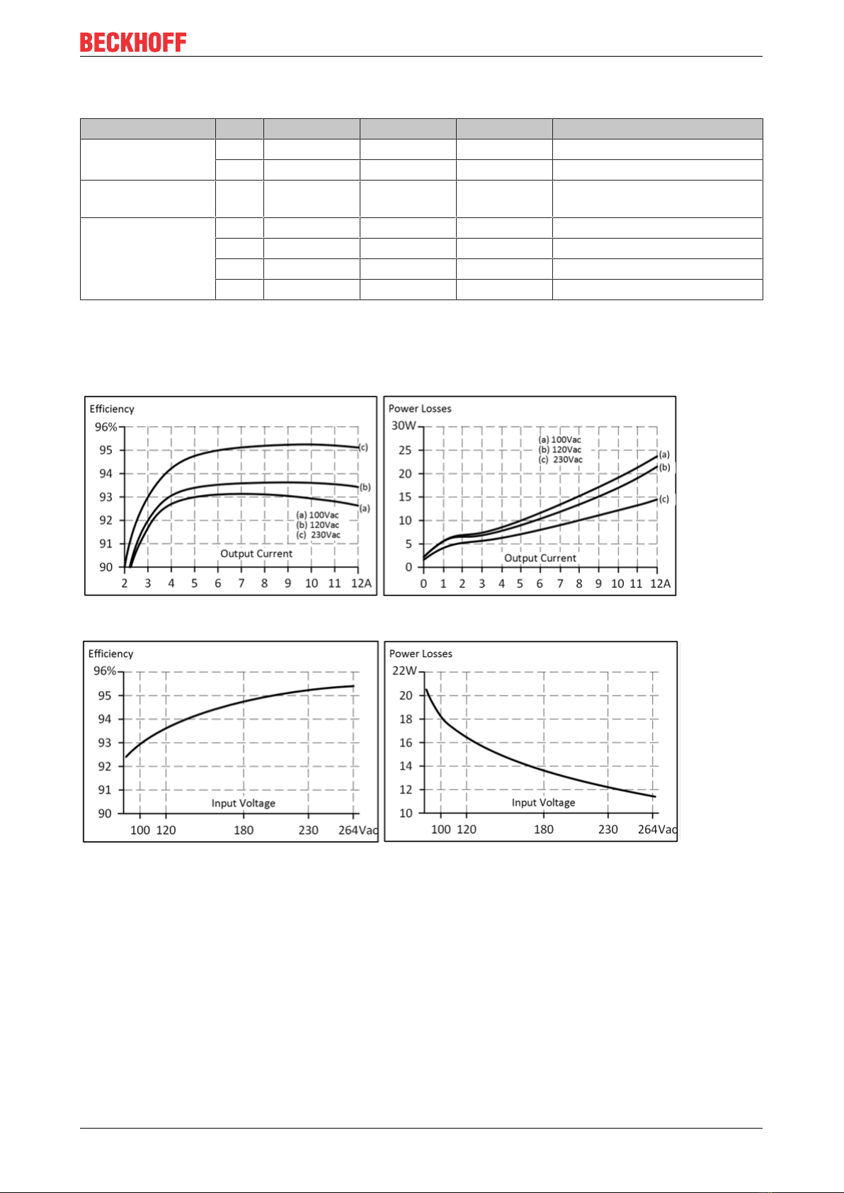
3.7 Efficiency and losses
AC 100V AC 120V AC 230V
Efficiency Typ. 92.9% 93.6% 95.2% At 24V, 10A
Typ. 92.5% 93.4% 95.1% At 24V, 12A (Extra Power)
Average efficiency*) Typ. 92.5% 93.0% 94.3% 25% at 2.5A, 25% at 5A,
25% at 7.5A. 25% at 10A
Losses Typ. 2.5W 2.1W 1.8W At 24V, 0A
Typ. 9.8W 8.9W 7.1W At 24V, 5A
Typ. 18.3W 16.4W 12.1W At 24V, 10A
Typ. 23.4W 21.7W 14.8W At 24V, 12A (Extra Power)
*) The average efficiency is based on assumptions for a typical application with the power supply unit
operating at 25% of the nominal load during 25% of the time, 50% of the nominal load during 25% of the
time, 75% of the nominal load during 25% of the time and 100% of the nominal load during the remaining
time.
Fig.10: Efficiency over output current; losses over output current
Fig.11: Efficiency over input voltage; losses over input voltage
Technical data, mounting, wiring
PS2001-2410-000018 Version: 1.0
3.8 Lifetime expectancy
The lifetime expectancy shown in the table indicates the minimum number of operating hours (service life)
and is determined by the lifetime expectancy of the built-in electrolytic capacitors. The lifetime expectancy is
stated in operating hours and is calculated according to the specifications of the capacitor manufacturer. The
manufacturer of the electrolytic capacitors only guarantees a maximum life of up to 15 years (131,400h). Any
number exceeding this value represents a calculated theoretical lifetime which can be used to compare
devices.
AC 100V AC 120V AC 230V
Lifetime
expectancy
128,000h 141,000h 176,000h At 24V, 5A and +40°C
61,000h 75,000h 120,000h At 24V, 10A and +40°C
47,000h 59,000h 101,000h At 24V, 12A and +40°C
363,000h 399,000h 499,000h At 24V, 5A and +25°C
173,000h 211,000h 338,000h At 24V, 10A and +25°C
132,000h 166,000h 286,000h At 24V, 12A and +25°C
3.9 MTBF
MTBF stands for Mean Time Between Failure, which is calculated from the statistical failure rate of the
components and indicates the reliability of a device. It is a statistical representation of the probability of
equipment failure and does not necessarily represent the service life of a product.
The MTBF number is a statistical representation of the probability of equipment failure. An MTBF number of
1,000,000h, for example, means that statistically, if there are 10,000 devices in use, one device will fail every
100 hours. However, it is not possible to say whether the failed device has been in operation for 50,000
hours or only 100 hours.
For these device types the MTTF value (Mean Time To Failure) is identical to the MTBF value.
AC 100V AC 120V AC 230V
MTBF SN 29500,
IEC 61709
550,000h 560,000h 661,000h At 24V, 10A and 40°C
1,003,000h 1,017,000h 1,176,000h At 24V, 10A and +25°C
MTBF MIL HDBK
217F
188,000h 188,000h 213,000h At 24V, 10A and 40°C; Ground Benign GB40
252,000h 252,000h 290,000h At 24V, 10A and 25°C; Ground Benign GB25
40,000h 40,000h 47,000h At 24V, 10A and 40°C; Ground Fixed GF40
51,000h 51,000h 61,000h At 24V, 10A and 25°C; Ground Fixed GF25

Technical data, mounting, wiring
PS2001-2410-0000 19Version: 1.0
3.10 Terminals and wiring
The terminals are designed to be finger-safe according to IP20 and are suitable for field or factory wiring.
Technical data Input Output DC-OK signal
Connection cross-section e*: max. 6mm²
f*: max. 4mm²
a*: max. 4mm² (d<2.8mm)
e*: max. 6mm²
f*: max. 4mm²
a*: max 4mm² (d<2.8mm)
e*: max. 1.5mm²
f*: max. 1.5mm²
a*: max. 1.5mm²
(d<1.6mm)
Connection cross section
(AWG)
e*: AWG 20-10
f*: AWG 20-10
a* AWG 20-10 (d<2.8mm)
e*: AWG 20-10
f*: AWG 20-10
a* AWG 20-10
(d<2.8mm)
e*: AWG 24-16
f*: AWG 24-16
a*: AWG 24-16
(d<1.6mm)
Strip length 7mm / 0.28inch 7mm / 0.28inch 7mm / 0.28inch
e* = solid single wire
f* = stranded wire
a* = with ferrule
Wiring instructions:
• Use suitable copper cables that are designed for at least the following operating temperatures: +60°C
for ambient temperatures up to +45°C, +75°C for ambient temperatures up to +60°C, and +90°C for
ambient temperatures up to +70°C.
• Observe the national installation rules and regulations!
• Make sure that all single wires of a strand are connected to the terminal!
• Unused terminals should be tightened firmly.
• Ferrules are permitted.
Series connection of power supply units:
Power supply units may be connected in series.
Series connection (looping from one power supply output to the next) is permitted as long as the average
output current flowing through a connection pin does not exceed 25A. For higher currents please use a
separate distributor terminal strip as shown in Fig. Using distribution terminals.
Fig.12: Series connection of outputs; use of distribution terminals

Technical data, mounting, wiring
PS2001-2410-000020 Version: 1.0
3.11 Functional wiring diagram
Fig.13: Functional wiring diagram
Table of contents
Popular Power Supply manuals by other brands


HP
HP StorageWorks 2312 Replacement instructions

Matsusada Precision
Matsusada Precision CO Series instruction manual

Wibre
Wibre 5.0630.10.32 installation manual

Thermaltake
Thermaltake TR2 500W user manual

Extron electronics
Extron electronics PS 1242 installation guide

PORT CONNECT
PORT CONNECT 26-811-183 user guide