Vanner LIFESTAR 20-1050CUL-DC User manual

VANNER
Incorporated Owner’s Manual
LifeStar Owner’s Manual - 1 -
LifeStar
Ambulance Power Module
Model
20-1050CUL-DC
20-1000TUL-DC

VANNER
Incorporated Owner’s Manual
LifeStar Owner’s Manual - 2 -
Table of Contents
Table of Contents....................................................................................................2
Section 1 : General Installation Diagram.................................................................3
Section 2 : Introduction...........................................................................................4
Section 3. Functionality ..........................................................................................4
Inverter Function...............................................................................................4
Battery Charger.................................................................................................5
DC Power Output..............................................................................................5
Section 4: Specifications.........................................................................................6
Unpacking the Ambulance Power Module ........................................................7
Installing the Ambulance Power Module...........................................................7
Inverter Lamp Description ................................................................................9
Section 6: Installing the Inverter and Charger Remote Status Display Panels .......10
Section 7: Operating the 20-1050CUL-DC Ambulance Power Module ................11
Section 8: Troubleshooting the 20-1050CUL-DC.................................................12

VANNER
Incorporated Owner’s Manual
LifeStar Owner’s Manual - 3 -
Section 1 : General Installation Diagram

VANNER
Incorporated Owner’s Manual
LifeStar Owner’s Manual - 4 -
Section 2: Introduction
Thank you for purchasing a Vanner Ambulance Power Module for your emergency vehicle. We are
confident you will be satisfied with its performance.
Vanner products are designed and manufactured by skilled professionals using the highest standards in
workmanship, guaranteeing excellent performance and reliability for your emergency vehicle. With
minimum maintenance and care, you can expect years of trouble-free service from your Vanner product.
The 20-1050CUL-DC is a 12 VDC to 120 VAC inverter with a built-in battery charger/conditioner, transfer
relay and KKK Spec 12V Portable Equipment Charging Circuit. This unit is equipped with an AC line cord
for connecting AC input power (shore/utility power) and a receptacle with a Ground Fault Circuit
Interrupter (GFCI) for AC output. This enables you to plug AC loads directly into the inverter. The DC
cables have quick connectors to facilitate installation and pre-wiring of emergency vehicles. The 12V
Portable Equipment Charging Circuit has a spring clamp for ease of installation. The transfer relay is
powered by +12Vdc, the unit must be connected to the DC source for the transfer relay to work.
The 20-1000TUL-DC is a 12 VDC to 120 VAC inverter with transfer relay and KKK Spec 12V Portable
Equipment Charging Circuit. This unit is equipped with an AC line cord for connecting AC input power
(shore/utility power) and a receptacle with a Ground Fault Circuit Interrupter (GFCI) for AC output. This
enables you to plug AC loads directly into the inverter. The DC cables have quick connectors to facilitate
installation and pre-wiring of emergency vehicles. The 12V Portable Equipment Charging Circuit has a
spring clamp for ease of installation. The transfer relay is powered by 120VAC, the transfer relay will
engage without the unit being connected to the DC source.
This manual is written around the 20-1050CUL-DC, all sections of this manual that refer to the Charger
section of the unit does not apply to the 20-1000TUL-DC.
Section 3: Functionality
WARNING : Battery input cables must be connected to the battery with proper polarity to avoid
damaging the inverter.
NOTE : If the battery is fully charged at the time AC input is applied, the unit will go directly into Ready/
Maintenance mode.
Inverter Function
The 20-1050CUL-DC converts battery power to 1050 Watts of 120 VAC modified sine wave power to
operate vital emergency vehicle equipment. The unit is easily connected to the positive and negative
posts of a battery system with appropriate fusing, and when turned on, produces 120 VAC True RMS
voltage.
The inverter also has an energy-saving feature called Load Demand. With this feature, the inverter output
is pulsed, significantly reducing the current draw from the battery until a demand is made on its output.
Continuous output of 120 VAC resumes when a load greater than 20 Watts is applied. The load demand
feature can be disabled with the Setup Switch on the front panel.
A built-in transfer relay switches the AC output receptacle from the inverter to the AC input when the unit
senses AC input from the shore/utility power.

VANNER
Incorporated Owner’s Manual
LifeStar Owner’s Manual - 5 -
Battery Charger
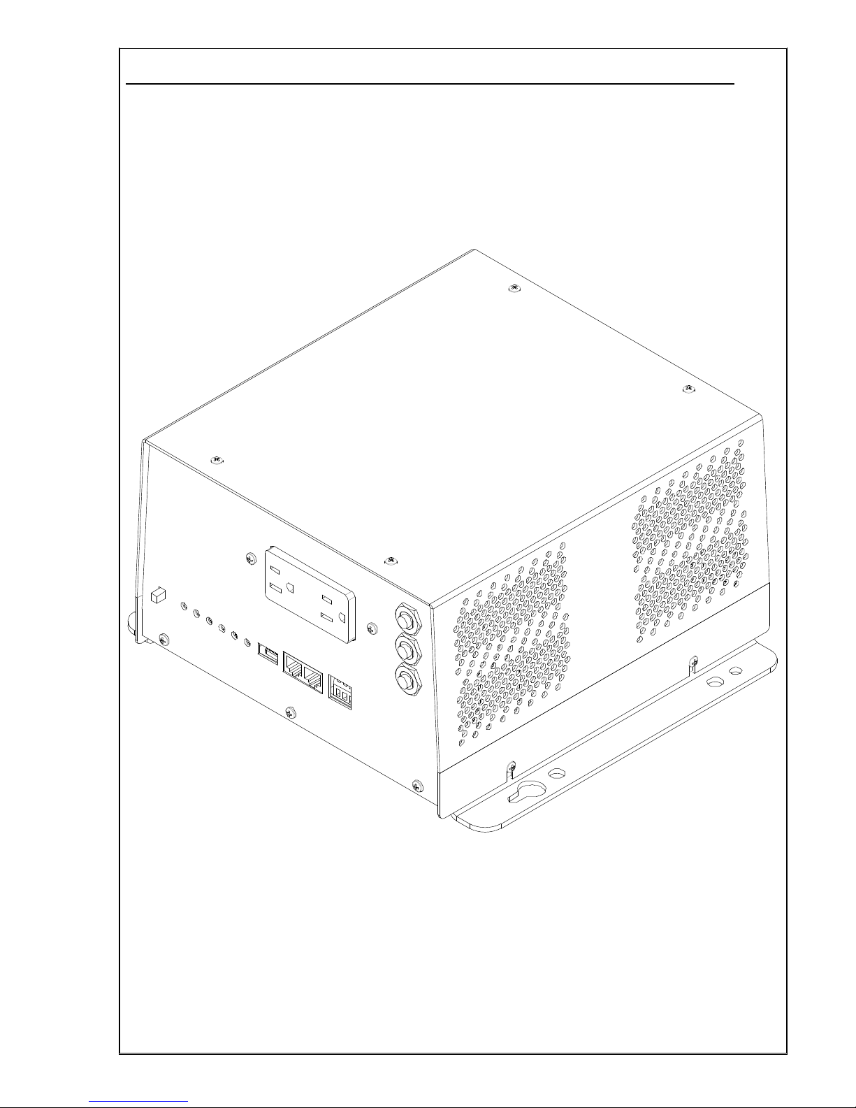
The 20-1050CUL-DC Battery Charger's superior design incorporates a multi-stage charger. This design
enables the unit to automatically charge batteries, maintaining the battery's integrity and reducing the
likelihood of premature failure.
* Bulk Absorption Charge Mode
While in the Bulk Charge mode, the unit continuously charges at a constant current of 55 Amps (high
setting) this is the factory setting, or 15.0 Amps (low setting) The unit will charge until battery voltage
reaches 14.2 VDC for flooded battery setting, or 14.1 VDC for gel battery setting. The unit then supplies a
fixed voltage for one hour.
* Ready/Maintenance Mode
The charger automatically enters the Ready/Maintenance mode, maintaining the battery’s proper voltage
of 13.2 VDC for flooded battery setting, or 13.6 VDC for gel battery setting. This Ready/Maintenance
mode is designed to eliminate gassing (overcharging), helping to extend the life of the battery.
A Setup Switch is located on the front panel for selecting the type of battery (Flooded Lead Acid or Gel
Lead Acid), charger output current (High/Low), and Load Demand (On/Off).
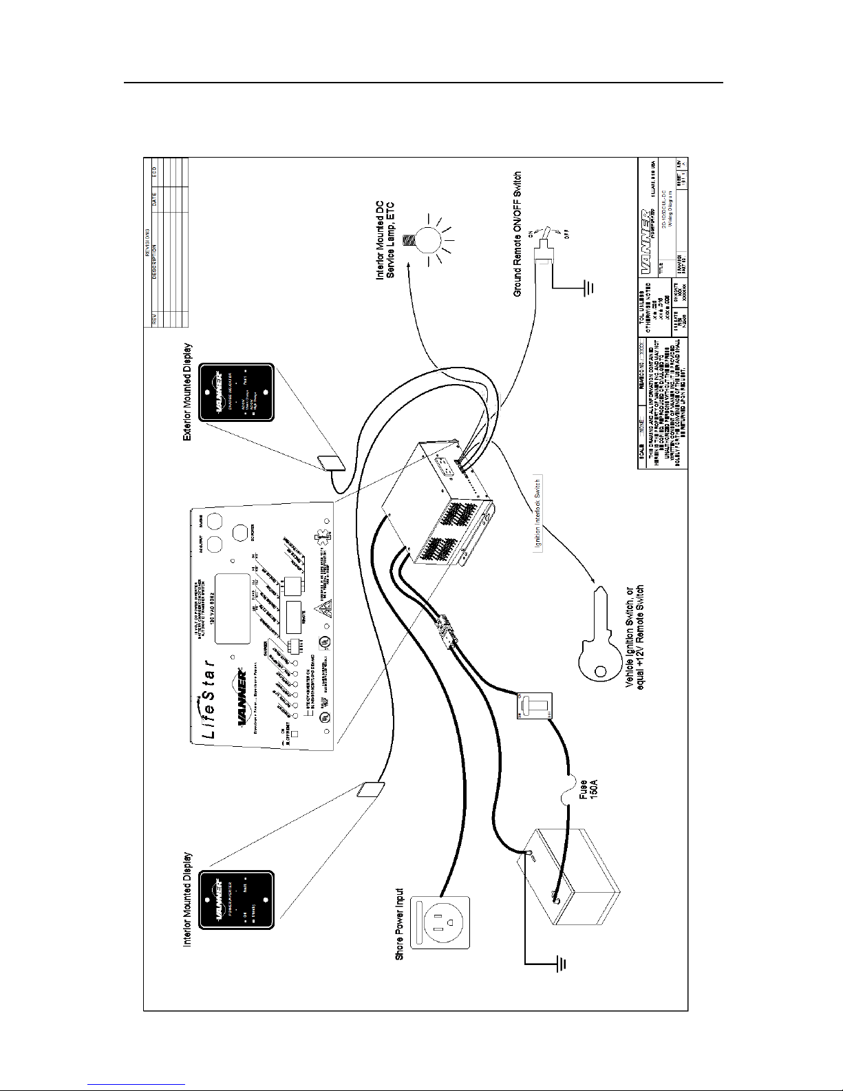
Remote Control
Built-in remote control capability is provided for use with a customer supplied +12v signal and with a
customer supplied Ground signal. Either one, both or neither may be used.
To activate +12v remote control set the dip switch labeled IGNITION to the ON position. Connect the
+12v remote control signal wire to the compression terminal labeled IGNITION.
To activate GROUND control set the dip switch labeled REMOTE to the ON position. Connect the
GROUND control signal wire to the compression terminal labeled REMOTE.
If no remote control is required set both dip switches to the OFF position.
The unit can be used with the IFM1 Interface Module and is fully backward compatible for retrofitting
installations that already have the IFM1 Interface Module. To use the IFM1 set the dip switches labeled
IGNITION and GROUND to the OFF position. Plug the IFM1 modular cord into either 8-pin socket.
DC Power Output
The 20-1050CUL-DC DC Power Output complies with KKK section 3.7.7.2 for PORTABLE EQUIPMENT
CHARGING CIRCUIT. Which states “A circuit shall be furnished for charging all portable battery powered
devices, i.e. suction units, hand lights, portable radios, etc. This circuit shall prevent discharge of chassis
batteries by only permitting the charging of portable devices when the vehicle is either running or the
optional battery conditioner is connected to shore power. Circuit breaker protection shall be provided and
shall have a minimum 10 amp capacity. An additional tagged, identified lead shall be furnished in both the
cab and module for connection of additional (future) portable equipment that requires recharging.”
DC Power (battery power) is available while +12V Remote Switch Terminal is energized and while the
20-1050CUL-DC is in battery charger mode. DC output is protected by a 20A circuit breaker label “DC
Power”
This manual suits for next models
1
Table of contents
Popular Power Supply manuals by other brands

Videx
Videx 520MR Installation instruction

Poppstar
Poppstar 1008821 Instructions for use

TDK-Lambda
TDK-Lambda LZS-A1000-3 Installation, operation and maintenance manual

TDK-Lambda
TDK-Lambda 500A instruction manual

Calira
Calira EVS 17/07-DS/IU operating instructions

Monacor
Monacor PS-12CCD instruction manual