Beco HCA92640 User manual
www.beko.com
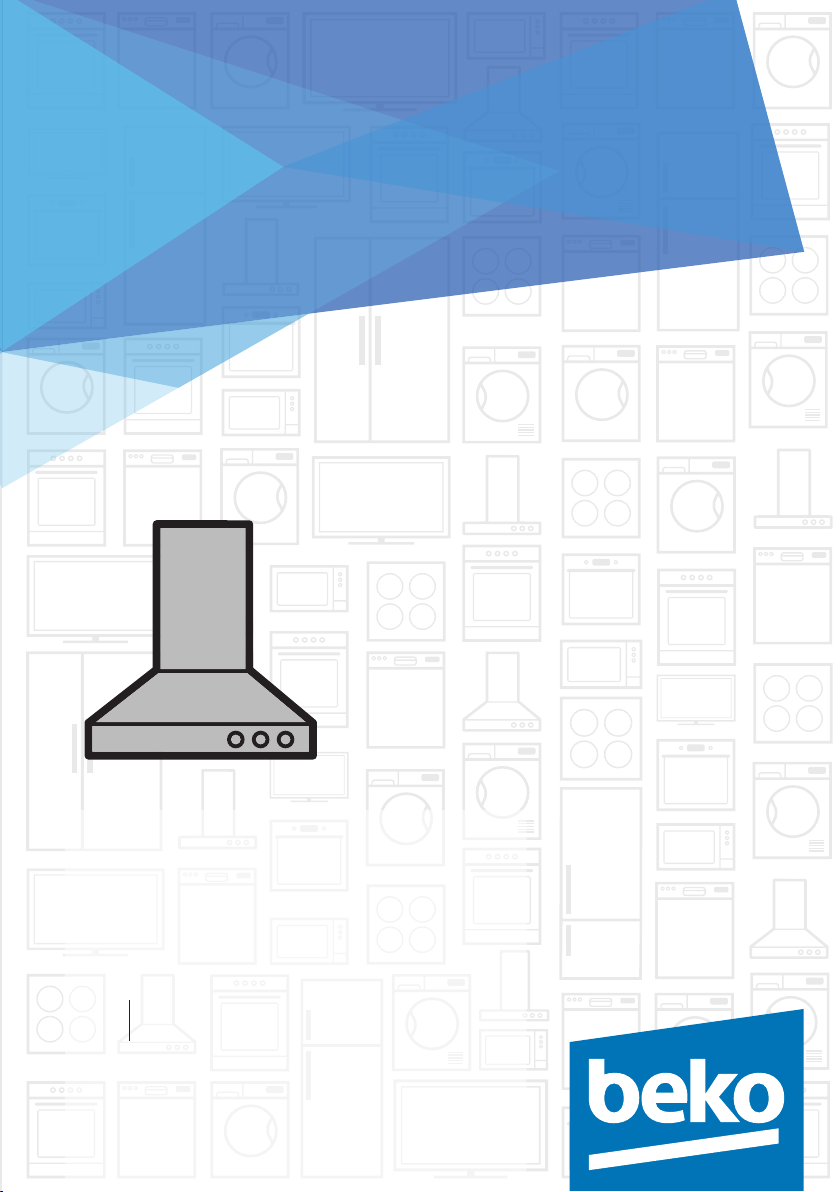
Hood
User manual
HCA92640
HCA62640
01M-8848793200-0119-06
EN AR

Comples wth the WEEE Drectve.
Ths product was manufactured usng the latest technology n envronmentally frendly condtons.
Please read this user manual first!
Dear Customer,
Thank you for preferring a Beko product. We hope that you get the best results from
your product which has been manufactured with high quality and state-of-the-art
technology. Therefore, please read this entire user manual and all other accompanying
documents carefully before using the product and keep it as a reference for future use.
If you handover the product to someone else, give the user manual as well. Follow all
warnings and information in the user manual.
Rememberthatthisuser manualis alsoapplicable forseveralothermodels. Differences
between models will be identified in the manual.
Explanation of symbols
Throughout this user manual the following symbols are used:
C
Important information or useful hints
about usage.
A
Warning for hazardous situations
with regard to life and property.
B
Warning for electric shock.
Does not contan PCB.

3 / EN
Hood / User Manual
CONTENTS
ENGLISH 04-19
20-34

Hood / User Manual
4 / EN
1Important nstructons for safety and envronment
This section contains safety in-
structions that will help protect
from risk of personal injury or prop-
erty damage. All warranties will be-
come void if you do not follow these
instructions.
1.1 General safety
•Always have the installation and
repairing procedures carried out
by the Authorised Service Agent.
Manufacturer shall not be held
responsible for damages arising
from procedures carried out by
unauthorised persons.
•This appliance is not intended for
use by persons (including chil-
dren) with reduced physical, sen-
sory or mental capabilities, or lack
of experience and knowledge.
Children should be supervised to
ensure that they do not play with
the appliance.
1.1.1 Electrcal safety
•Disconnect the product from the
mains during installation, main-
tenance, cleaning and repairing
procedures.
•If the power cable is damaged, it
must be replaced by the manufac-
turer, after sales service or a sim-
ilarly qualified person (preferably
an electrician) or someone desig-
nated by the importer in order to
avoid possible risks.
•Operating voltage is 220 to 240
volts.
•If the appliance has a failure, it
should not be operated unless
it is repaired by the Authorised
Service Agent. There is the risk of
electric shock!
•Do not route power cable close to
hobs. Otherwise power cable may
cause fire since it melts down eas-
ily.
•Never plug the hood before instal-
lation is completed.
•In order to obtain the best perfor-
mance, external conductor must
not be longer than 4 m. It must not
contain more than 2 perpendicu-
lar (90°) angles and its diameter
must be min. ø120 mm.
•Disconnect the appliance before
any intervention to the internal
parts of the appliance.

5 / EN
Hood / User Manual
1Important nstructons for safety and envronment
1.1.2 Product safety
•You can use a pipe with a diameter
of 120 mm or 150 mm on the flue
connection of the hood.
•Do not make connections to the
flues connected with stoves, ex-
haust shafts or flues with rising
flames. Observe the rules set by
authorities on the discharge of
exhaust air.
•The height between the lower
surface of the hood and upper
surface of the stove/oven should
not be less than 65 cm.
•Do not operate the hood without
aluminum filters and do not remove
the filters while it is operated.
•Never touch the hood's lamp after
they operated for a long time. Hot
lamps may burn your hand.
•Avoid big flames beneath the
product. Otherwise, particles on
oil filter may ignite and lead to a
fire.
•Turn on the hobs after placing
pans or pots on it. Otherwise, ris-
ing temperature may deform cer-
tain parts of your product.
•Turn off the hobs before taking
away pans or pots.
•Avoid inflammable materials
under the hood.
•Oil may ignite while frying foods.
Therefore, be careful about cloths
and curtains.
•Never leave the cooker unat-
tended when frying foods; other-
wise boiled oil may cause fire.
•There is the risk of fire if your
hood is not cleaned in the speci-
fied periods.
•Be extremely careful and wear
gloves when cleaning the hood.
•We advise you to operate the
appliance a few minutes before
starting to cook in order to in-
crease the suction power. Thus,
you shall have a continuous and
stable suction power when the
vapors arises.
•Operate your hood for 15 minutes
more after the end of cooking or
frying in order to remove smell
cooking vapour in the kitchen.
•When the hood is in use, espe-
cially together with gas cookers,
make sure that environment is
ventilated with clean air.
•Pay attention not to connect
the appliance to the flues used
by non-electrical devices. (E.g.:
Heater flue).
This manual suits for next models
1
Table of contents
Languages:
Other Beco Ventilation Hood manuals


Popular Ventilation Hood manuals by other brands

Gorenje
Gorenje S3 IHGC963S4X manual

KOBE
KOBE ISX2136SQB-1 Installation instructions and operation manual

U.S. Products
U.S. Products ADVANTAGE-100H Information & operating instructions

Kuppersberg
Kuppersberg DUDL 4 LX Technical Passport

Framtid
Framtid HW280 manual

Thermador
Thermador HGEW 36 FS installation manual


