Becx Machines DRHS55 User manual
Manual
DRHS55
Version: 01
July 2019
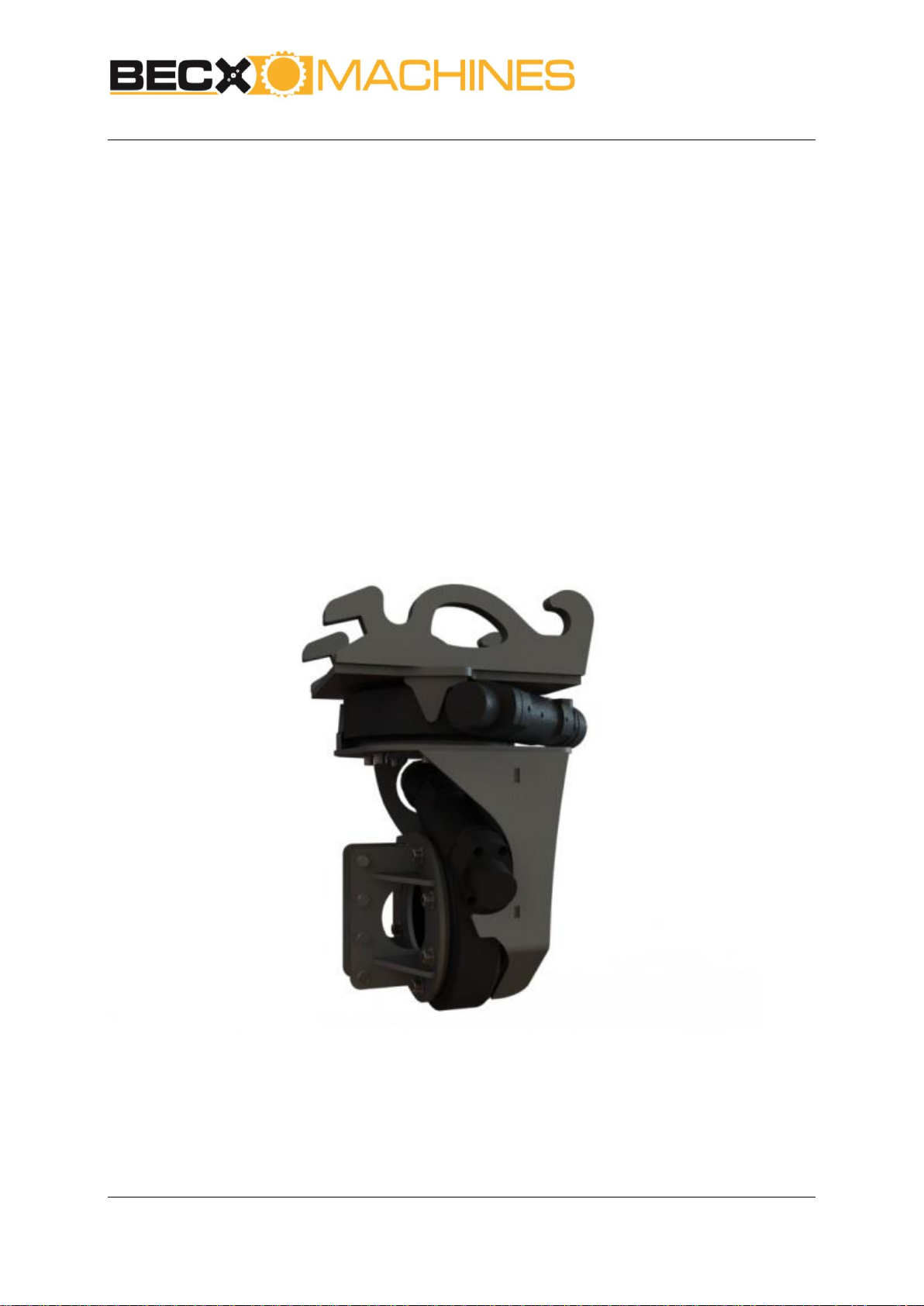
Double Rotator
DRHS55
User manual

Manual
DRHS55
Version: 01
July 2019
Page 2 of 21
Manufacturer: Becx Machines B.V.
De Sonman 35
5066 GJ Moergestel
Tel: +31 (0)13 2070760
info@becxmachines.com
http://www.becxmachines.com
© Copyright July 2019
Nothing in this publication may be replicated and/or published in print, photocopy, microfilm, sound
recording, electronically or otherwise without the prior explicit written permission from Becx
Machines B.V.
Becx Machines B.V. retains the right to change parts of the system and the contents of this manual at
any time without prior notification giving or immediate notice to the customer.
Becx Machines B.V. takes the greatest care to guarantee an accurate, and where necessary, complete
description of all parts. Nevertheless, it cannot be held liable for damage due to inaccuracies and/or
deficiencies in this manual.
Manual
DRHS55
Version: 01
July 2019
Page 3 of 21
Foreword
The Becx double rotator is specially developed to convey tools in as flexible and stable manner as
possible from the mini-crane/digger to the object to be worked on. As standard, this double rotator
unit has a universal CW10 quick-release connection.
Please read this manual carefully before you use the support arm. Always observe
the safety requirements as set out in Section 2.
Read the user manual of the tool to be used before you attach and use the
support arm. Always observe the safety requirements as set out in the tool’s user
manual.
A copy of this manual must be kept with the support arm and be available to the
user. All important maintenance work and relevant notes must be recorded by the
maintenance company.
It is the user’s responsibility to select a suitable tool holder for the support arm
and ensure that it is correctly attached and connected to the arm.

Manual
DRHS55
Version: 01
July 2019
Page 4 of 21
Table of contents
FOREWORD.................................................................................................................................. 3
TABLE OF CONTENTS .................................................................................................................... 4
DECLARATION OF CONFORMITY (IIA) (COPY)................................................................................. 5
OVERVIEW OF SYMBOLS............................................................................................................... 6
PICTOGRAMS ........................................................................................................................................... 7
1. TECHNICAL SPECIFICATIONS................................................................................................... 8
2. SAFETY .................................................................................................................................. 9
3. DESCRIPTION OF COMPONENTS........................................................................................... 11
3.1. TOOL NESTING PLACE ................................................................................................................... 11
3.2. SUPPORT ARM COMPONENTS ........................................................................................................ 12
4. OPERATION ......................................................................................................................... 13
4.1. MAKE THE SUPPORT ARM READY FOR USE........................................................................................ 13
4.2. CARRY OUT THE WORK ACTIVITIES................................................................................................... 14
5. MAINTENANCE .................................................................................................................... 15
6. MALFUNCTION ANALYSIS..................................................................................................... 16
7. DISPOSAL ............................................................................................................................ 17
8. LOGBOOK............................................................................................................................ 18
8.1. MAINTENANCE WORK .................................................................................................................. 18
8.2. REPAIRS /REPLACEMENTS............................................................................................................. 19
8.3. MALFUNCTIONS .......................................................................................................................... 20
8.4. INSPECTIONS............................................................................................................................... 21

Manual
DRHS55
Version: 01
July 2019
Page 5 of 21
Declaration of conformity (IIa) (copy)
We:
Becx Machines B.V.
De Sonman 35
5066 GJ Moergestel
declare entirely under our own responsibility that the product:
Description :Double Rotator
Type :DRHS55
Serial number :…….....................
with respect to this declaration, conforms to the provisions of the Directives:
Machinery directive 2006/42/EC
In accordance with the following standards:
NEN-EN-12100 Safety of machinery. Basic concepts, general principles for design.
NEN-EN ISO 4413 Hydraulic fluid power - General rules and safety requirements for
systems and their components
NEN-ISO 4254-1 Agricultural machinery - Safety - Part 1: General requirements
Director, Erwin Hommen
The Netherlands, Moergestel,
Date …………………………
Table of contents
Other Becx Machines Lawn And Garden Equipment manuals


Popular Lawn And Garden Equipment manuals by other brands

Sunforce
Sunforce SOLAR user manual

GARDEN OF EDEN
GARDEN OF EDEN 55627 user manual

Goizper Group
Goizper Group MATABI POLMINOR instruction manual

Rain Bird
Rain Bird 11000 Series Operation & maintenance manual

Cub Cadet
Cub Cadet BB 230 brochure

EXTOL PREMIUM
EXTOL PREMIUM 8891590 Translation of the original user manual


Vertex
Vertex 1/3 HP Maintenance instructions

GHE
GHE AeroFlo 80 manual

Land Pride
Land Pride Post Hole Diggers HD25 Operator's manual

Yazoo/Kees
Yazoo/Kees Z9 Commercial Collection System Z9A Operator's & parts manual

Premier designs
Premier designs WindGarden 26829 Assembly instructions

Snapper
Snapper 1691351 installation instructions