Becx Machines WLA60 User manual

Loader arm
Type: WLA60
Version: 1
July 2019
Loader arm
WLA60
User Manual

Loader arm
Type: WLA60
Version: 1
July 2019
Page 2 van 23
Manufacturer Becx Machines B.V.
De Sonman 35
5066 GJ Moergestel
Tel: +31 (0)13-207 07 60
http://www.becxmachines.com
© Copyright 2019
Nothing in this publication may be reproduced and/or made public in any form by print, photocopy,
microfilm, recording tape, electronically or by any other means without prior written permission
from Becx Machines B.V.
Becx Machines B.V. reserves the right to modify parts of the system, including the contents of this
manual, at any moment, without prior or direct notification to the buyer.
Although Becx Machines B.V. has taken the greatest care to make sure that individual parts have
been described correctly and in full where necessary, it accepts no liability for damage as a result of
inaccuracies or incompleteness of this manual.
Loader arm
Type: WLA60
Version: 1
July 2019
Page 3 van 23
Preface
From now on, you can get your loader even wider deployed using the WLA60.
This hydraulic arm makes it possible to mount a Becx hedge cutter to your loader. The WLA60 is
designed to fit onto almost any loader. If your loader does not have the two required double-acting
hydraulic valves, Becx can offer you valves + a control box-set as an option. The WLA60 is 60cm
extensible and offers a 105 degrees tilt. The arm can be used left or right and can be mounted to the
front or rear of your machine. Combined with the lift of your wheel loader this allows you cut nearly
every hedge. The WLA60 can carry our HS130HR and HS150HR hedge cutters, and even our new
HS131HR hedge cutter.
Carefully read this manual before using the loader arm. Always
follow the safety instructions set out in chapter 3.
One copy of this manual must be kept with the loader arm and must
be available to the user. All important servicing sessions and any
comments must be recorded and retained by the servicing company.
The user is responsible for selecting a suitable tool carrier for the
loader arm and its tools and for ensuring that the loader arm and
tool is properly attached and connected.

Loader arm
Type: WLA60
Version: 1
July 2019
Page 4 van 23
Table of contents
PREFACE ...................................................................................................................................... 3
TABLE OF CONTENTS .................................................................................................................... 4
FIGURES....................................................................................................................................... 4
CERTIFICATE OF CONFORMITY (IIA) (COPY) ................................................................................... 5
LIST OF SYMBOLS ......................................................................................................................... 6
1. TECHNICAL DATA................................................................................................................... 7
2. SAFETY .................................................................................................................................. 8
2.1. GENERAL...................................................................................................................................... 8
2.2. IN USE ......................................................................................................................................... 8
2.3. OPERATING PERSONNEL.................................................................................................................. 9
2.4. SAFETY SYMBOLS ON THE MACHINE .................................................................................................. 9
3. COMPONENT DESCRIPTION ................................................................................................. 10
3.1. ATTACHMENT ............................................................................................................................. 11
3.2. MECHANICAL COMPONENTS.......................................................................................................... 12
3.3. WEAR-AND GREASE PARTS LOADER ARM......................................................................................... 13
4. HYDRAULIC SCHEMES .......................................................................................................... 14
5. OPERATIONS ....................................................................................................................... 15
5.1. ASSEMBLY AND ADJUSTMENT OF THE LOADER ARM ........................................................................... 15
5.2. CARRY OUT THE WORKS................................................................................................................ 16
6. MAINTENANCE .................................................................................................................... 17
7. FAILURE ANALYSES .............................................................................................................. 18
8. REMOVAL............................................................................................................................ 19
9. LOGBOOK............................................................................................................................ 20
9.1. MAINTENANCE SERVICING,REPAIRS/REPLACEMENTS,FAULTS AND INSPECTIONS .................................... 20
Figures
FIGURE 1: OVERVIEW ................................................................................................................................. 10
FIGURE 2: ATTACHMENT PLATE .................................................................................................................... 11
FIGURE 3: GENERAL OVERVIEW OF THE MECHANICAL COMPONENTS................................................................... 12
FIGURE 4: OVERVIEW WEAR-AND GREASE PARTS LOADER ARM ......................................................................... 13
FIGURE 5: HYDRAULIC SCHEME –WITHOUT VALVE BLOCK ................................................................................. 14
FIGURE 6: HYDRAULIC SCHEME –WITH VALVE BLOCK....................................................................................... 14
FIGURE 7: MAXIMUM FORCES ARM AND TOOL ................................................................................................ 15

Loader arm
Type: WLA60
Version: 1
July 2019
Page 5 van 23
Certificate of conformity (IIa) (copy)
We:
Becx Machines B.V.
De Sonman 35
5066 GJ Moergestel
declare entirely under our sole responsibility, that this product:
Description : Loader arm
Type : BECX WLA60
Serial number : .....................
to which this declaration applies, complies with the provisions of the Directives:
Machinery Directive 2006/42/EC
Complies with the following standards:
NEN-EN-12100-1 Safety of machinery. Basic definitions, general design principles.
Part 1: Basic terminology, methodology
NEN-EN-12100-2 Safety of machinery. General design principles. Part 2: Technical
principles and descriptions
NEN-EN 982 Safety of machines –Safety requirements for hydraulic and
pneumatic systems and their components: Hydraulics
NEN-EN 14121-1 Safety of machines –Risk assessment –Part 1: Principles
Director; Erwin Hommen
Netherlands, Moergestel,
Date: .........................

Loader arm
Type: WLA60
Version: 1
July 2019
Page 6 van 23
List of symbols
This manual uses the following symbols for all actions and situations where the safety of the operator or
technician is at stake and where it is necessary to act with caution:
Warning!
Explanation.

Loader arm
Type: WLA60
Version: 1
July 2019
Page 7 van 23
1. Technical data
Description
Value
Unit
General
Noise pressure
See tool carrier
dB(A)
Vibration level in normal use
n/a
Hydraulic oil filtering requirements
10
microns
Oil for the drive
HV-46 or equivalent
Grease for greasing cutting heads
NLGI 2
Dimensions and weights
Length in*
1.315
mm
Length out*
1915
mm
Width *
320
mm
Height without/ with valves
400 / 460
mm
Own weight without/ with valves *
90 / 100
kg
Attachment information
Type
Screwable adapter plate
-
Attachment information
Standard attachment tube
80*80
mm
Available mounting width
250
mm
Force on attachment point (see Figure 7)
2700
N
Hanging moment (see Figure 7)
1300
Nm
Connection data
Maximum operating pressure
210
bar
Connection without valves
Connection pressure / drains single acting (1x) ***
1/2"
Connection pressure / drains double action (2x)
3/8”
Drain line connection ***
3/8”
Connection with valves
Connection pressure / drains single acting
1/2"
Drain line connection
3/8”
Valve-control (2x)
12
V
Fuse
10
A
Electrical connection to loader
12V-connector
* Exclusive tool and wheel loader
** Depending on the number of hydraulic control functions the loader features
*** For use with Becx hedge trimmer

Loader arm
Type: WLA60
Version: 1
July 2019
Page 8 van 23
2. Safety
2.1. General
No modifications must be made to the loader arm.
The user is responsible for making sure that the correct loader and adapter
are used (see chapter Fout! Verwijzingsbron niet gevonden.). The following
re important points in this regard:
The maximum pressure and number of revolutions (oil flow) must not be
exceeded. Excess pressure and excess revving can damage the machine and
cause injury.
The tool carrier must be strong and stable enough to absorb the forces and
moments exerted by the loader arm safely and under all circumstances.
2.2. In use
Consult the tool carrier manual for the noise rating. Because this is
considerably louder than the loader arm itself, the noise load of the tool
carrier determines the rating.
The machinery must only be used for the activities for which it is designed.
Persons or animals who are present in or who approach the danger zone must
be stopped immediately and the weed brush must be switched off.
If passers by disrupt the work too much, the operator can consider
temporarily cordoning off the site.
If the loader arm starts to make a different sound and/or starts to vibrate,
work must stop immediately and the weed brush has to be switched off. Work
can only continue after the source of the noise has been identified and
resolved.
Always complete inspection and maintenance jobs.
The machinery must not be used for any other purposes during inspection and
maintenance.
The hydraulic feed to the loader arm must be disconnected during inspection,
maintenance or cleaning to prevent accidental operation.
Always comply with local work regulations and safety rules.
If the machinery is used in the dark, use sufficient lighting (approx. 50 lux at
the work site).

Loader arm
Type: WLA60
Version: 1
July 2019
Page 9 van 23
2.3. Operating personnel
Operating personnel must be over 18.
Only persons who have received permission from the owner are allowed to
operate the system.
Persons must only carry out jobs for which they are trained. This applies to
both maintenance work and normal operations.
Personnel who operate equipment must be familiar with all possible
situations that could arise.
The owner or person in charge must be told if personnel operating machinery
identify faults or hazards or do not agree with safety measures.
2.4. Safety symbols on the machine
1.
Read the manual before use!
2.
Safety zone
Loader arm
Type: WLA60
Version: 1
July 2019
Page 10 van 23
2
1
3
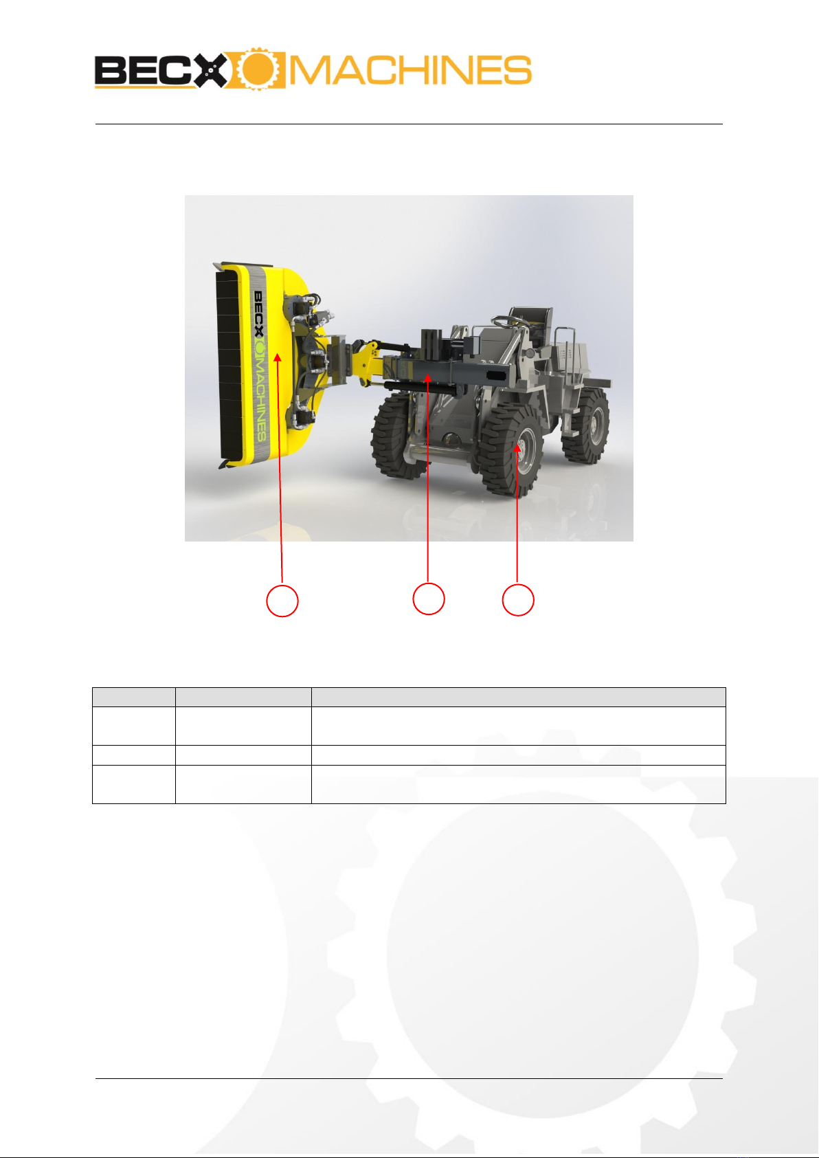
3. Component description
Figure 1: Overview
Figure 1
Part
explanation
1
Loader
The loader is not supplied. The user is responsible for using a
tool carrier that is suitable for the loader.
2
Loader arm
The loader arm couples the tool to the loader.
3
Tool
The tool is not supplied. The user is responsible for using a
tool that is suitable for the loader arm and loader.
Loader arm
Type: WLA60
Version: 1
July 2019
Page 11 van 23
1
2
3
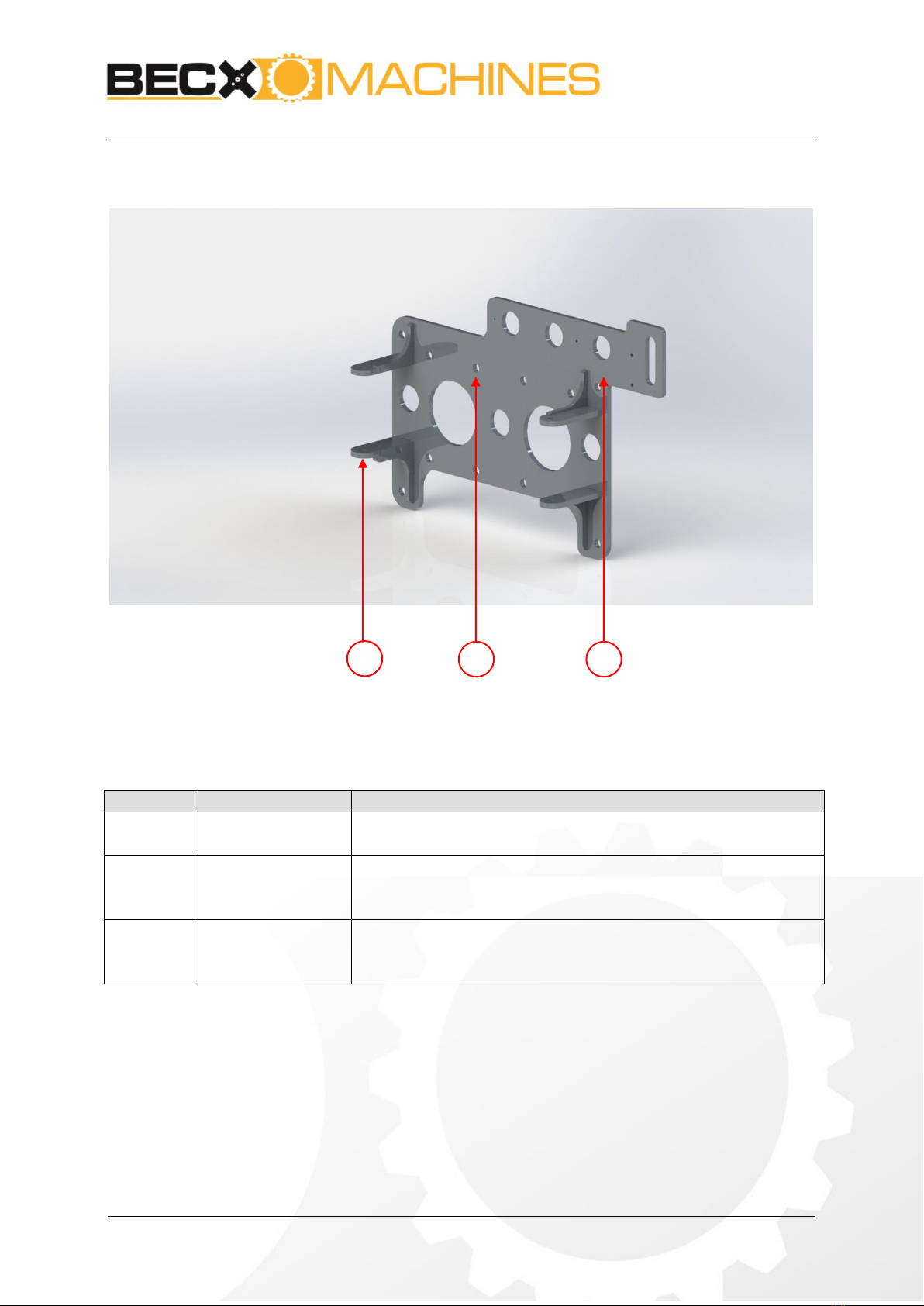
3.1. Attachment
Figure 2: Attachment plate
Figure 2
Part
Explanation
1
Arm clamp
The actual support arm is attached by means of clamps on the
adapter plate. This is done with the two mounting bolts
2
Adapter plate
Using a minimum of 4 of the 12 fixing holes WLA60 can be
attached to almost any loader. It is preferred to us the holes
on the sides of the plate
3
Valve block
connection
If the version including control valve is provided, this is
located at the appropriate position. In the version without
valve block this section on the adapter plate is not present.
Loader arm
Type: WLA60
Version: 1
July 2019
Page 12 van 23
7
1
2
3
4
5
6
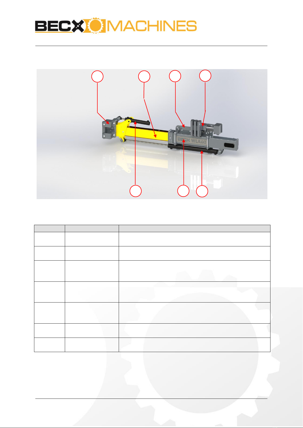
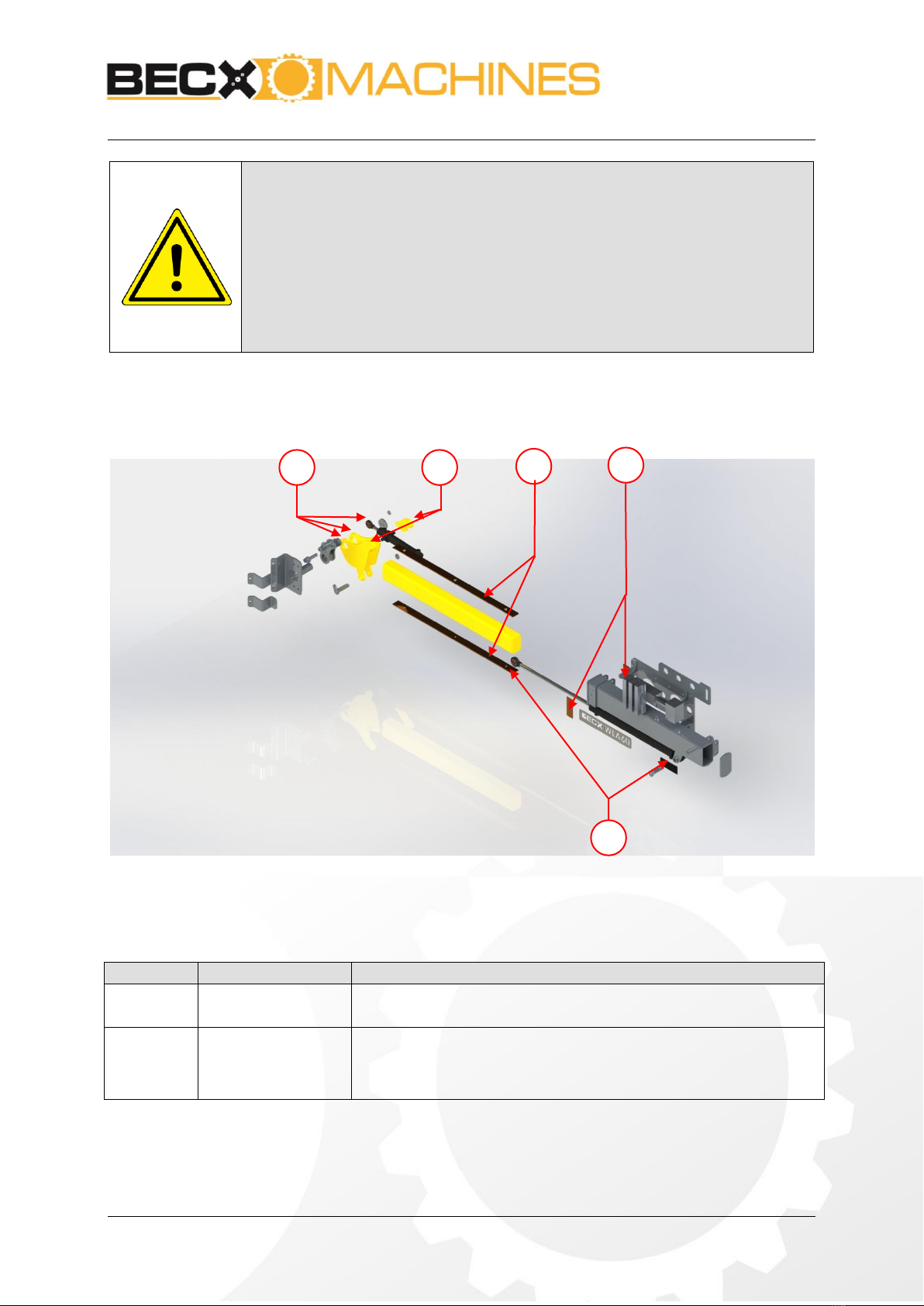
3.2. Mechanical components
Figure 3: General overview of the mechanical components
Figure 3
Part
Explanation
1
Clamp
With this clamp, the tool, for example a Becx hedge cutter,
can be coupled to the arm
2
Side-shift
By side-shifting this part, the tool can moved to the left or
right.
3
Adapter plate
Using a minimum of 4 of the 12 fixing holes WLA60 can be
attached to almost any loader. It is preferred to us the holes
on the sides of the plate
4
Valve block
Optionally, the control valve can be supplied. This converts
to one single-acting hydraulic function to two double-acting
functions and a single-action function.
5
Cylinder to rotate
By using this cylinder the tool will be rotated up to 110
degrees. This can be used to switch between the cutting on
top, or on the side of the hedge.
6
Base
This section is the base of the arm. This connects all the
components together.
7
Side-shift cylinder
By using this cylinder, the tool can be side-shifted up to
60cm to the left or right
Loader arm
Type: WLA60
Version: 1
July 2019
Page 13 van 23
1
1
1
2
2
ATTENTION!
Depending on the loader, this arm can be delivered with two double-
acting electric functions. By default, the machine is delivered without
valve block, but with the necessary hydraulic fittings and hoses supplied.
See the supplied electrical and hydraulic diagrams for your model.
It is the responsibility of the user to link the machine in the right manner
to the tool and loader.
3.3. Wear- and grease parts loader arm
Figure 4: Overview wear- and grease parts loader arm
Figure 3
Part
Explanation
1
Grease points
Squeeze grease into the grease nipples on the cutting heads.
See Chapter 1: Technical data or the grease specification
2
Wear strips
During use, these parts will wear out. When the strips are
worn onto the screw heads, these parts should be replaced
per set (4 strips)
Loader arm
Type: WLA60
Version: 1
July 2019
Page 14 van 23
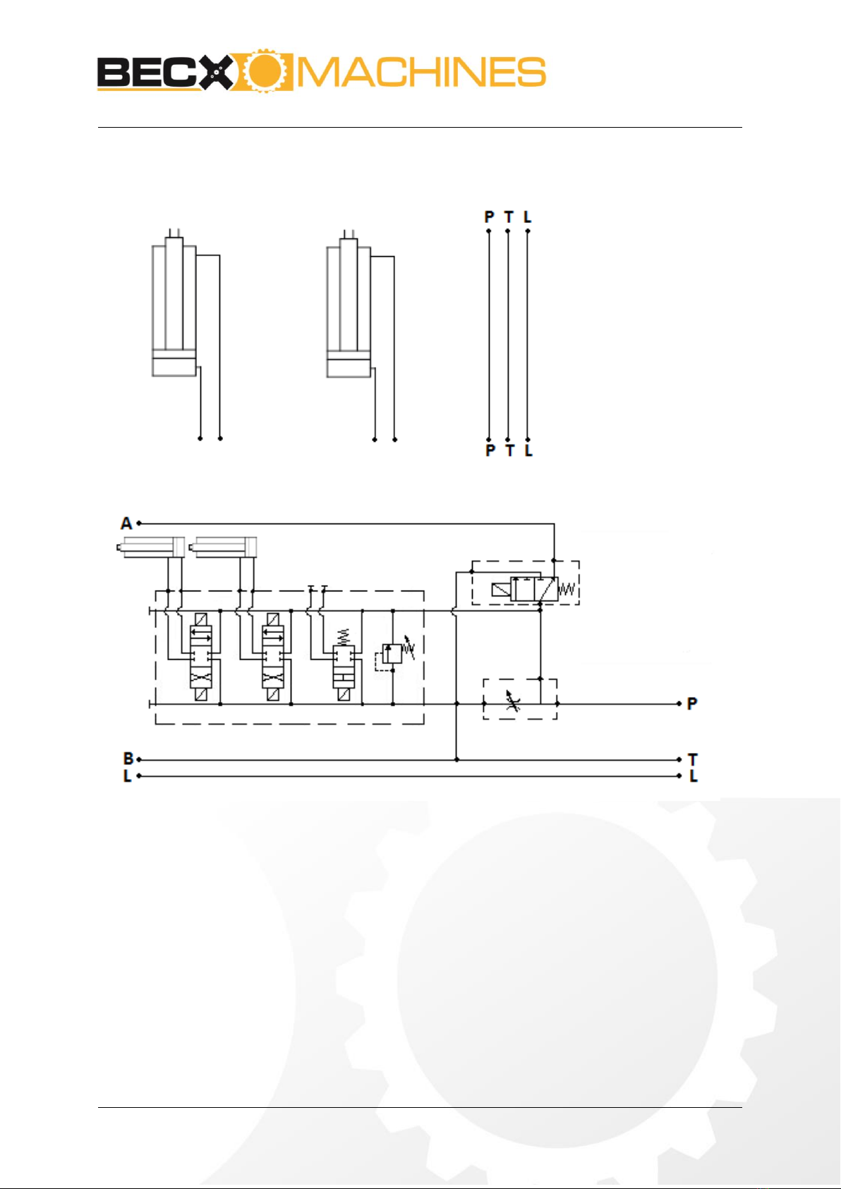
4. Hydraulic schemes
Figure 5: Hydraulic scheme –without valve block
Figure 6: Hydraulic scheme –with valve block

Loader arm
Type: WLA60
Version: 1
July 2019
Page 15 van 23
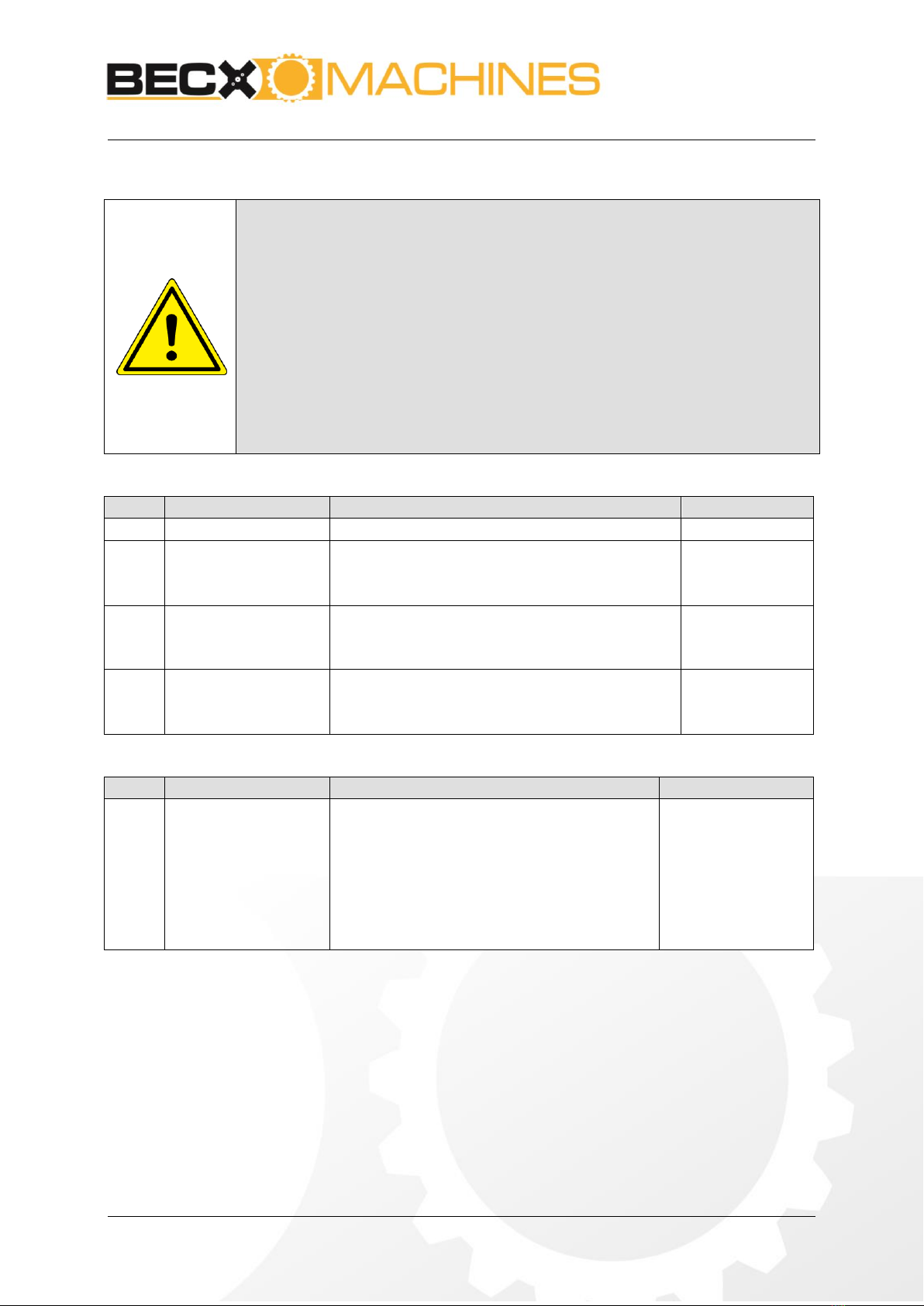
5. Operations
5.1. Assembly and adjustment of the loader arm
Figure 7: maximum forces arm and tool
No.
What to do
Action
Result
1
Select the correct tool
carrier and lifting arm
Make sure that the tool carrier and lifting
arm are sufficiently strong and stable for
the weed brush (see chapter 1: Technical
data for the load when lifting and the
exerted moment of the lifting).
Make sure that the maximum pressure
and number of revolutions (oil flow) are
not exceeded.
Make sure that the correct rapid
attachment connections are installed.
Make sure that the correct clasp is used.
Ignoring the stated
values can result in
damage to
equipment and
injury to persons.
2
Connect the loader
arm to the loader
mechanically
Make sure the base is vertical
Connect the adapter plate (Figure
3:3) with at least 4 of the provided 12
connection holes to the loader.
Place the base (Figure 3:6) on the
desired position on the adapter plate.
Depending on the preference of the
user, it can be mounted on different
positions.
Lock the base properly
Moment tool
Vertical force tool

Loader arm
Type: WLA60
Version: 1
July 2019
Page 16 van 23
2
Connect the hoses
Connect the rapid attachment
connections for the feed line, return
line and drain line.
3
Adjust the hydraulic
system
Adjust the setting of the hydraulic
aggregate so that the maximum
pressure and number of revolutions
cannot be exceeded.
This will depend on the type of tool
carrier that is used. Please refer to
the manual of the tool carrier.
5.2. Carry out the works.
Observe the safety-instructions in chapter Fout! Verwijzingsbron niet
evonden..
Observe the manual of the loader for the correct operation of the control
functions.
Observe the manual of the loader the right safety-instructions.
Loader arm
Type: WLA60
Version: 1
July 2019
Page 17 van 23
6. Maintenance
Only components supplied or approved by the manufacturer must be used for
replacement or repair of parts.
Always disconnect the loader arm from the feed lines when work is carried
out on the machinery. This is done by disconnecting the rapid attachments.
Only persons who can show that they have adequate knowledge of
mechanical and hydraulic machinery through their training and experience are
allowed to carry out maintenance work.
The installation can be cleansed with a high pressure cleanser, never point
directly at hydraulic components.
Weekly maintenance
No.
What to do
Action
Result
1
Tightening bolts
Check and tighten all bolts
2
Visual check
Visually check the construction and hydraulic
aggregate for damage and cracks.
Check cylinder-rods for damages and dirt.
3
Wear strip check
Check if the strips are worn onto the bolt
heads (see chapter 3.3), if so, replace all 4
strips.
4
Grease
Squeeze grease into the grease nipples. These
are located at all pivot points.
See 1 Technical data for type
Annual maintenance
No.
What to do
Action
Result
1
Inspect
Check following parts for damage, cracks and
looseness:
Connections.
Hoses.
Couplings.
Pivot points.
Wear strips.

Loader arm
Type: WLA60
Version: 1
July 2019
Page 18 van 23
7. Failure analyses
Breakdown
Remedy
1
Not enough hydraulic power
available
Check the hydraulic hoses.
2
After switching on, the tool
does not run
Check that the hydraulic hoses are correctly connected.
3
Switching between hydraulic
functions doesn’t work
Check the electrical circuit.
Check the operation of the control valve.
If the fault cannot be solved by following the above recommendations, consult your dealer or
maintenance department.

Loader arm
Type: WLA60
Version: 1
July 2019
Page 19 van 23
8. Removal
When replacing parts or at the end of the part's lifecycle, please ensure that all materials are
disposed of, destroyed or recycled in a legal and environmentally friendly way.

Loader arm
Type: WLA60
Version: 1
July 2019
Page 20 van 23
9. Logbook
9.1. Maintenance servicing, repairs/replacements, faults and
inspections
The following must be recorded in this logbook:
All annual maintenance services (sheet 1)
All repairs/replacements (sheet 2)
Faults (sheet 3)
Inspections (sheet 4)
Maintenance servicing
Date
Passed by:
Description
Table of contents
Other Becx Machines Lawn And Garden Equipment manuals


Popular Lawn And Garden Equipment manuals by other brands

New England Arbors
New England Arbors Athens Assembly instructions

Blumfeldt
Blumfeldt Solid Sky Expand manual

Westfalia
Westfalia 946960 manual

Truvox International
Truvox International R48HD Cimex HD user manual

Dancover
Dancover Garden Storage Box Regular A manual

Coleman
Coleman Moscuito Deleto Instructions for use


