Bedford B550-2001 User manual

B550 Series
Sensorless Vector Frequency Drive
Installation & Quick-Start Manual


B550 Series sensorless vector frequency drive
Preface
Thank you for choosing B550 series sensorless vector frequency Drive. B550 series
are manufactured by adopting high-quality components, material and incorporating the
latest microprocessor technology available.
Getting Started
This manual will be helpful in the installation, parameter setting, troubleshooting, and daily
maintenance of the AC motor drives. To guarantee safe operation of the equipment, read
the following safety guidelines before connecting power to the AC motor drives. Keep
this operating manual handy and distribute to all users for reference.
! WARNING
!Always read this manual thoroughly before using B550 series AC Motor Drives.
!DANGER! AC input power must be disconnected before any maintenance. Do not
connect or disconnect wires and connectors while power is applied to the circuit.
Maintenance must be performed by qualified technicians.
!CAUTION! There are highly sensitive MOS components on the printed circuit boards.
These components are especially sensitive to static electricity. To avoid damage to
these components, do not touch these components or the circuit boards with metal
objects or your bare hands.
!DANGER! A charge may still remain in the DC-link capacitor with hazardous voltages
even if the power has been turned off. To avoid personal injury, please ensure that
power has turned off before operating AC drive and wait ten minutes for capacitors to
discharge to safe voltage levels.
!CAUTION! Ground the B550 series using the ground terminal. The grounding
method must comply with the laws of the country where the AC drive is to be installed.
refer to Basic Wiring Diagram.
!CAUTION! The final enclosures of the AC drive must comply with EN50178. (Live parts
shall be arranged in enclosures or located behind barriers that meet at least the
requirements of the Protective Type IP20. The top surface of the enclosures or barrier
that is easily accessible shall meet at least the requirements of the Protective Type
IP20). (Users must provide this environment for B550 series.)
!DANGER! The AC drive may be destroyed beyond repair if incorrect cables are
connected to the input/output terminals. Never connect the AC drive output terminals
U/T1, V/T2, and W/T3 directly to the AC main circuit power supply.

B550 Series sensorless vector frequency drive
TABLE OF CONTENTS
CHAPTER 1 RECEIVING AND INSPECTIONS
1.1 Nameplate Information ...................................................................... 1-1
1.2 Model Explanation ............................................................................. 1-1
1.3 Serial Number Explanation................................................................ 1-1
1.4 External Parts and Labels.................................................................. 1-2
CHAPTER 2 STORAGE AND INSTALLATION
2.1 Storage .............................................................................................. 2-1
2.2 Ambient Conditions............................................................................ 2-1
2.3 Installation ........................................................................................ 2-2
CHAPTER 3 WIRING
3.1 Basic Wiring Diagram ........................................................................ 3-2
3.2 External Wiring................................................................................... 3-3
3.3 Control Terminal Wiring ..................................................................... 3-4
3.4 Main Circuit Wiring............................................................................. 3-7
3.5 Wiring Notes ...................................................................................... 3-8
3.6 Motor Operation Precautions............................................................. 3-9
CHAPTER 4 DIGITAL KEYPAD OPERATION
4.1 Description of Digital Keypad ............................................................ 4-1
4.2 Explanation of LED Indicators ........................................................... 4-2
4.3 Explanation of Displayed Messages.................................................. 4-3
4.4 Keypad Operation.............................................................................. 4-4
CHAPTER 5 DESCRIPTION OF PARAMETER SETTINGS...................... 5-1

CHAPTER 6 MAINTENANCE AND INSPECTIONS
6.1 Periodic Inspection ............................................................................ 6-1
6.2 Periodic Maintenance ........................................................................ 6-1
CHAPTER 7 TROUBLESHOOTING AND FAULT INFORMATION .......... 7-1
CHAPTER 8 SUMMARY OF PARAMETER SETTING .............................. 8-1
APPENDIX A STANDARD SPECIFICATIONS .......................................... A-1
B550 Series sensorless vector frequency drive

This page intentionally left blank.
B550 Series sensorless vector frequency drive
1-1
CHAPTER 1 RECEIVING AND INSPECTION
This B550 series AC drive has gone through rigorous quality control tests at the factory
before shipment. After receiving the AC motor drive, please check for the following:
Receiving
9Check to make sure that the package includes an AC drive, the User Manual, and
rubber bushings.
9Inspect the unit to insure it was not damaged during shipment.
9Make sure that the part number indicated on the nameplate corresponds with the part
number of your order.
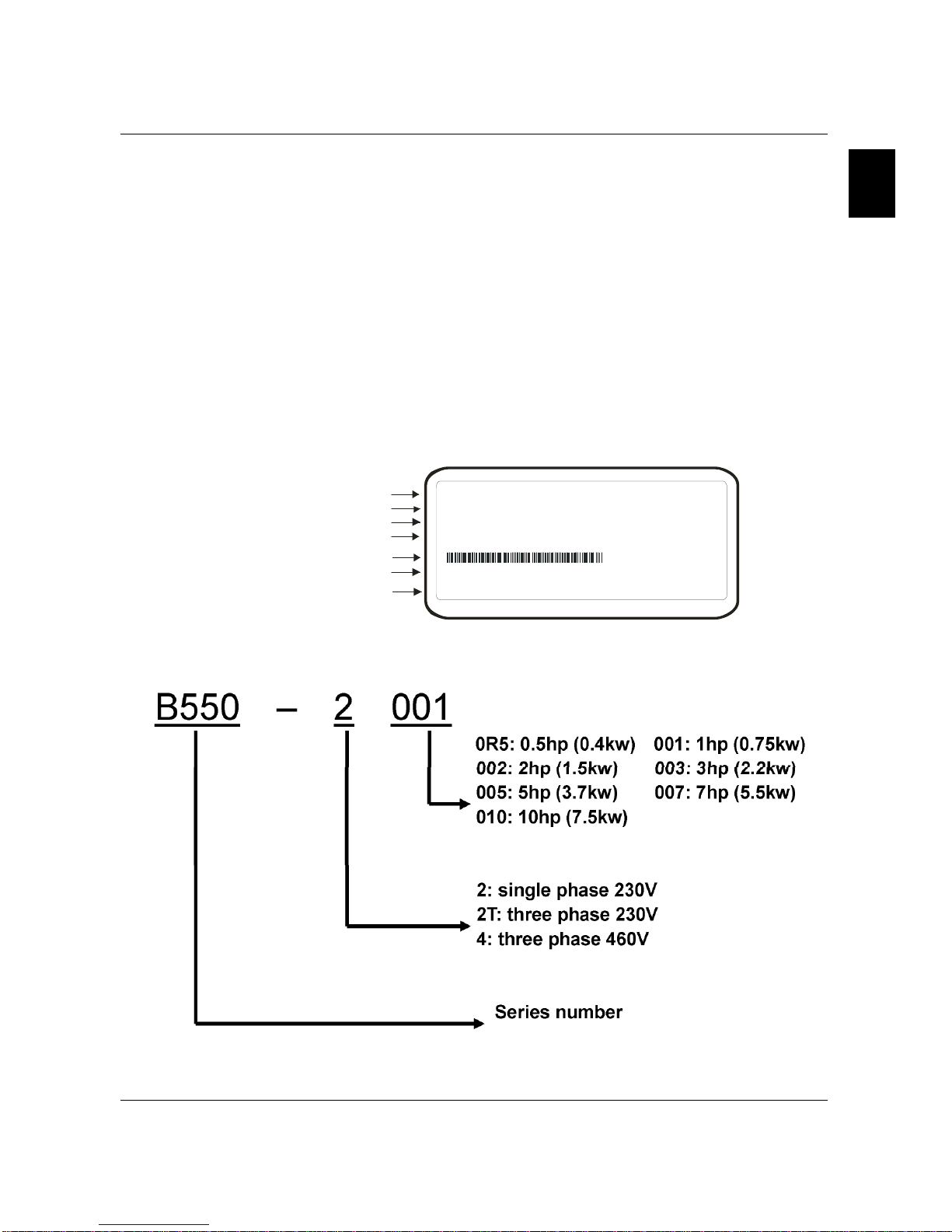
1.1 Nameplate Information: Example of 1HP 230V AC drive
MODE : B 5 5 0 - 2001
INPUT :3PH 200-240V 50/60Hz 6.0A
OUTPUT :3PH 0-240V 5.0A 1.9kVA 1HP
Freq. Ra nge :0.1~400Hz
007 M23A0T0 0112 30
Manufacturer:
AC Drive Model
Input Spec.
Output Spec.
Output Frequency Range
Bar Code
Serial Number
Software Version
1.2 Model Explanation
B550 Series sensorless vector frequency drive

1-2
1.4 External Parts and Labels
B550 Series sensorless vector frequency drive
B550 Series sensorless vector frequency drive
2
2-1
CHAPTER 2 STORAGE AND INSTALLATION
2.1 Storage
The AC drive should be kept in the shipping carton before installation. In order to retain the
warranty coverage, the AC drive should be stored properly when it is not to be used for an
extended period of time. Some storage suggestions are:
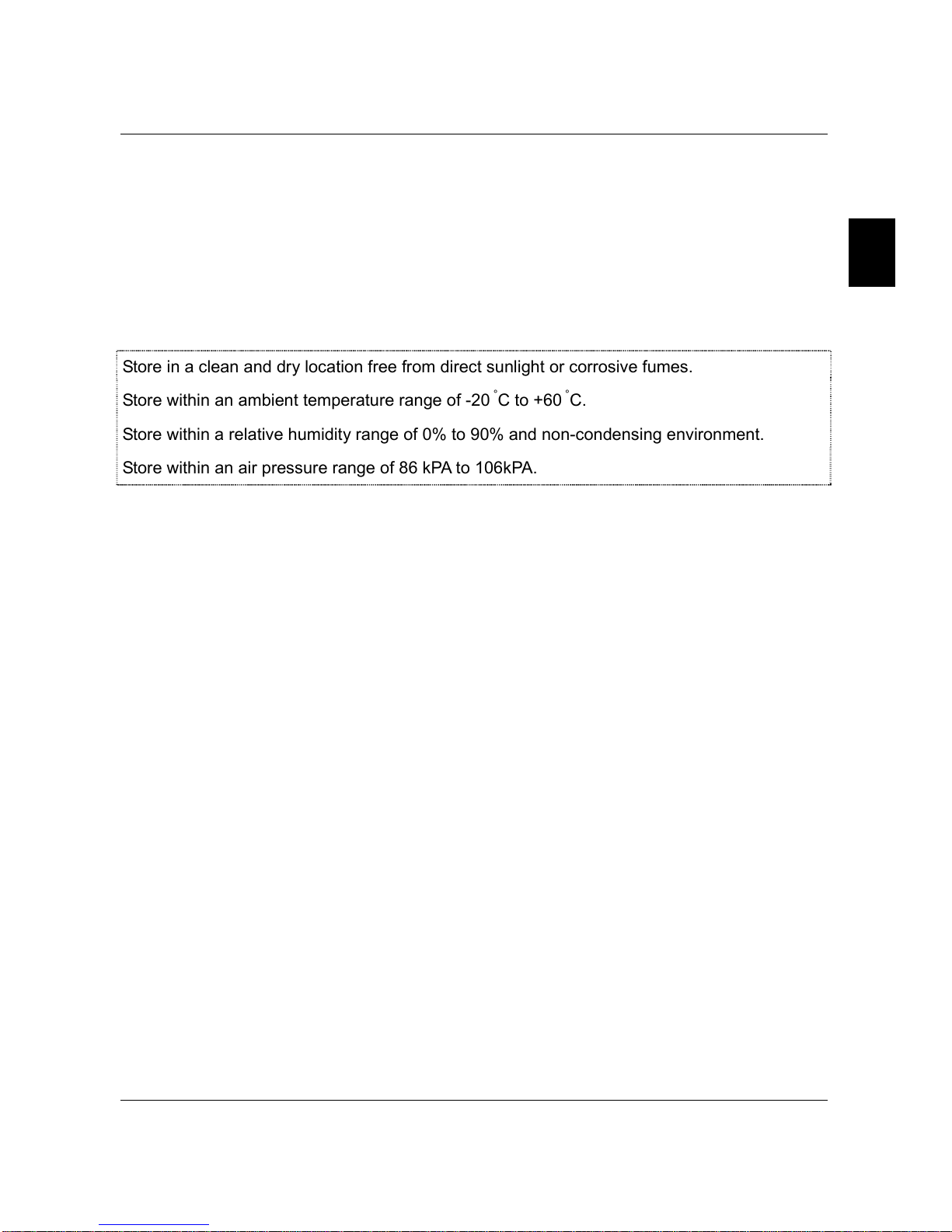
Store in a clean and dry location free from direct sunlight or corrosive fumes.
Store within an ambient temperature range of -20 °C to +60 °C.
Store within a relative humidity range of 0% to 90% and non-condensing environment.
Store within an air pressure range of 86 kPA to 106kPA.
2.2 Ambient Conditions
Operation Air Temperature: -10°C to +50°C (14°F to 122°F),
for 5.5 kW models and above: -10°C to +40°C (14°F to 104°F)
Relative Humidity: 0% to 90%, no condensation allowed
Atmosphere pressure: 86 to 106 kPa
Installation Site Altitude: below 1000m
Vibration: Maximum 9.80 m/s2(1G) at less than 20Hz
Maximum 5.88 m/s2(0.6G) at 20Hz to 50Hz
Storage Temperature: -20°C to +60°C (-4°F to 140°F)
Relative Humidity: Less than 90%, no condensation allowed
Atmosphere pressure: 86 to 106 kPa
Transportation Temperature: -20°C to +60°C (-4°F to 140°F)
Relative Humidity: Less than 90%, no condensation allowed
Atmosphere pressure: 86 to 106 kPa
Vibration: Maximum 9.80 m/s2(1G) at less than 20Hz, Maximum 5.88
m/s2(0.6G) at 20Hz to 50Hz
Pollution Degree 2: good for a factory type environment.
B550 Series sensorless vector frequency drive
2-2
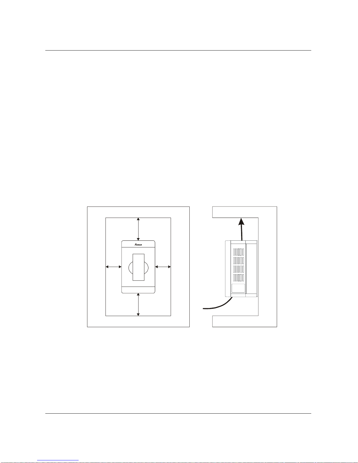
2.3 Installation:
Improper installation of the AC drive will greatly reduce its life. Be sure to observe the
following precautions when selecting a mounting location. Failure to observe these
precautions may void the warranty!
Do not mount the AC drive near heat-radiating elements or in direct sunlight.
Do not install the AC drive in a place subjected to high temperature, high humidity,
excessive vibration, corrosive gases or liquids, or airborne dust or metallic particles.
Mount the AC drive vertically and do not restrict the air flow to the heat sink fins.
The AC drive generates heat. Allow sufficient space around the unit for heat dissipation as
shown in the figure below:
150mm
150mm
50mm
50mm
Air Flow
B550 Series sensorless vector frequency drive

3
3-1
CHAPTER 3 WIRING
DANGER
Hazardous Voltage
Before accessing the AC drive:
Disconnect all power to the AC drive.
Wait five minutes for DC bus capacitors discharge.
Any Electrical or mechanical modification to this equipment without prior written
consent of Delta Electronics, Inc. will void all warranties and may result in a safety
hazard in addition to voiding the UL listing.
Short Circuit Withstand:
Suitable for use on a circuit capable of delivering not more than 5,000 rms symmetrical
amperes, for all 460V Models, the maximum is 480 Volts, 230V Models, the maximum is 240
Volts.
General Wiring Information
Applicable Codes
All B550 AC drives are Underwriters Laboratories, Inc.(UL) and Canadian Underwriters
Laboratories (cUL) listed, and therefore comply with the requirements of the National Electrical
Code (NEC) and the Canadian Electrical Code (CEC).
Installation intended to meet the UL and cUL requirements must follow the instructions
provided in “Wiring Notes” as a minimum standard. Follow all local codes that exceed UL and
cUL requirements. Refer to the technical data label affixed to the AC drive and the motor
nameplate for electrical data.
The "Line Fuse Specification" in Appendix B, lists the recommended fuse part number for each
M-Series part number. These fuses (or equivalent) must be used on all installations where
compliance with U.L. standards is a required.
B550 Series sensorless vector frequency drive
3-2
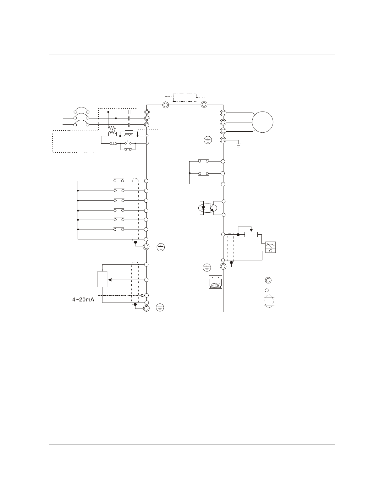
3.1 Basic Wiring Diagram
Users must connect wiring according to the following circuit diagram shown below.
B2 U/T1
V/T2
W/T3
IM
3~
MO1
MCM
RS-485
NOTE: Do not plug a Modem or telephone line to the RS-485 communication
port, permanent damage may result. Terminal 1& 2 are the power
sources for the optional copy keypad and should not be used while
using RS-485 communication.
6←1
B1
E
RA
RB
RC
120VAC/250VAC 5A
24VDC less than 2.5A
M0
M1
M2
M3
M4
M5
GND
AVI
GND
+10V 10mA(MAX)
3
2
1
VR
0
~
10VDC
VR
:
3K
~
5KΩ
A
FM
GND
+
-
VR(1KΩ)
DC 0
~
10V
RJ-11
1:15V
2:GND
3:SG-
4:SG+
5:Reserved
6:Reserved
Braking resistor (optional)
Main Circuit Power
The spec. of main circuit
terminal is M3.0
Factory default
Forward/Stop
Reverse/Stop
Reset
Multi-step 1
Multi-step 2
Multi-step 3
Common signal
Master Frequency setting
factory default is VR which is
on the digital keypad
Analog voltage
Analog current
Power for speed setting
series interface
AC Motor
Grounding
Multi-function indication
output contact
Factory default:
indicates malfunction
Multi-function Photocoupler
output contact 48VDC 50mA
Factory default: Indicates
during operation
Analog output
Factory default:
output frequency
For adjustment
Main circuit (power)
terminals
Control circuit terminals
Shielded leads
* If it is single phase model, please select any of the two input power
terminals in main circuit power.
* Single phase model can be input 3-phase power.
S/L2
T/L3
NFB
R/L1
S/L2
T/L3
SA
OFF
ON
MC
MC
RB
RC
Recommended Circuit
when power supply
is turned OFF by a
fault output
R/L1
ACI
E
E
E
B550 Series sensorless vector frequency drive

3
3-3
3.2 External Wiring
Motor
Output AC
Line Reactor
Power Supply
Magnetic
contactor
Input AC
Line Reactor
EMI Filter
R/L1 S/L2 T/L3
U/T1 V/T2 W/T3
B1
B2
Braking
Resistor
Zero-phase
Reactor
Zero-phase
Reactor
FUSE/NFB
Items Explanations
Power
supply
Please follow the specific power
supply requirement shown in
APPENDIX A.
Fuse/NFB
(Optional)
There may be inrush current during
power up. Please check the chart of
APPENDIX B and select the correct
fuse with rated current. NFB is
optional.
Magnetic
contactor
(Optional)
Please do not use a Magnetic
contactor as the I/O switch of the AC
drive, this will reduce the operating
life cycle of the AC drive.
Input AC
Line
Reactor
(Optional)
Used to improve the input power
factor, to reduce harmonics and
provide protection from AC line
disturbances. (Surge, switching
spike, power flick, etc.). AC line
reactor should be installed when the
power supply capacity is ≧500kVA
or phase lead reactor will be
switched. And the wiring distance
should not exceed 10m. Please refer
to Appendix B for detail.
Zero-phase
Reactor
(Ferrite
Core
Common
Choke)
(Optional)
Zero phase reactors are used to
reduce radio noise especially when
audio equipment installed near the
inverter. Effective for noise reduction
on both the input and output sides.
Attenuation quality is good for a
wide range from AM band to 10Mhz.
Appendix B specifies zero phase
reactors. (RF220X00A)
EMI filter
(Optional)
To reduce electromagnetic
interference. Please refer to
Appendix B for detail.
Braking
Resistor
(Optional)
Used to reduce stopping time of the
motor. Please refer to the chart on
Appendix B for specific Braking
Resistors.
Output AC
Line
Reactor
(Optional)
Motor surge voltage amplitudes
depending on motor cable length.
For long motor cable applications
(>10m), it is necessary to install on
the inverter output side.
B550 Series sensorless vector frequency drive

3-4
3.3 Control Terminal Wiring (Factory Settings)
M0 M1 M2 M3 M4 M5 GND AFM AVI
+10V
MCM
MO1
RA RB RC
Relay contactor
Output
Factory Setting
Bias
Potentiometer
Full scale voltmeter
0 to 10 VDC
Factory setting:
fault indication
Photo coupler
output
Forward/Stop
Reverse/Stop
Reset
Multi-step speed 1
Multi-step speed 2
Multi-step speed 3
ACI GND
4~20mA
Wire Type: 75 C, Copper Only
Torque: 4kgf-cm (3.5 in-lbf)
Wire Gauge: 24-12 AWG
Wire Type: Copper Only
Torque: 2kgf-cm (1.73 in-lbf)
Wire Gauge: 22-16 AWG
N PN mo de wi th out ext ern al p owe r
M0
M1
M2
M3
M5
M4
E
GND
+24V
24
Vdc
-
+
NPN Mode
NOTE
M0
M1
M2
M3
M5
M4
E
GND
+24V
NPN mode with external power
FactorySetting
Forward/Stop
Reverse/Stop
Reset
Multi-step 1
Multi-step 2
Multi-step 3
Common Signal
Multi-function
InputTerminals
Don't apply the mains voltage
directly to above t erminals.
FactorySetting
Multi-function
InputTerminals
Forward/Stop
Reverse/Stop
Reset
Multi-step 1
Multi-step 2
Multi-step 3
Terminal
Symbol Terminal Function Factory Settings (NPN mode)
RA Multi-Function Relay Output
(N.O.) a
RA-RC
Resistive Load
5A(N.O.)/3A(N.C.) 277Vac;
5A(N.O.)/3A(N.C.) 30Vdc
Refer to P45 for programming.
RB Multi-Function Relay Output
(N.C.) b
RB-RC
Resistive Load
5A(N.O.)/3A(N.C.) 277Vac;
5A(N.O.)/3A(N.C.) 30Vdc
B550 Series sensorless vector frequency drive
3
3-5
Terminal
Symbol Terminal Function Factory Settings (NPN mode)
RC Multi-function Relay Common 5A(N.O.)/3A(N.C.) 277Vac;
5A(N.O.)/3A(N.C.) 30Vdc
M0 Multi-function auxiliary input
M1 Multi-function input 1
M2 Multi-function input 2
M3 Multi-function input 3
M4 Multi-function input 4
M5 Multi-function input 5
M0~M5-GND
Refer to P38~P42 for programming the
multi-function inputs.
ON: the activation current is 10 mA.
OFF: leakage current tolerance is 10μA.
GND Common Signal
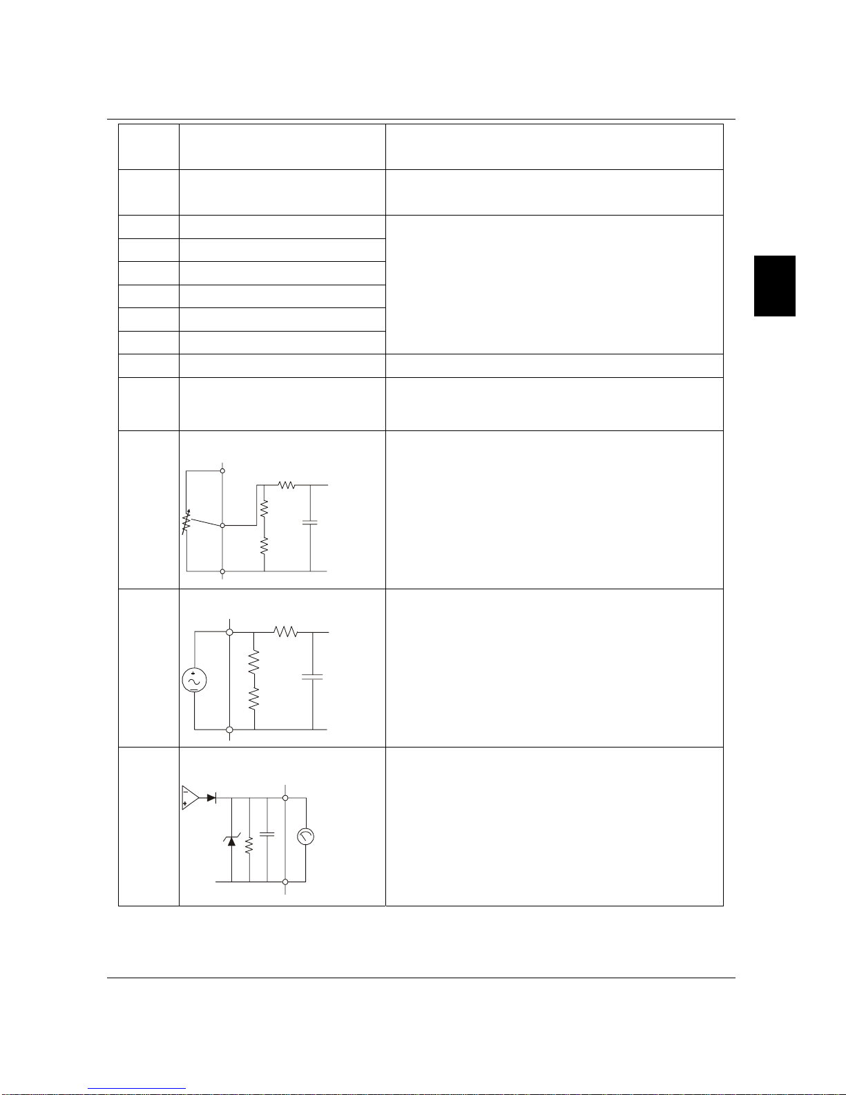
+10V +10 Vdc Output +10V-GND
It can supply +10 VDC power.
AVI
Analog Voltage Input
ACM
AVI
+10V
Internal Circuit
AVI Circuit
Impedance: 20kΩ
Resolution: 10 bits
Range: 0~10Vdc = 0~Max.Output Frequency
ACI
Analog Current Input
ACM
ACI
Internal Circuit
ACI Circuit
Impedance: 250Ω
Resolution: 10 bits
Range: 4~20mA = 0~Max.Output Frequency
AFM
Analog Output Meter
Internal Circuit
ACM Circuit
AFM
ACM
0~10V
Potentiometer
Max. 2mA
0 to 10V, 2mA
Impedance: 100kΩ
Output Current: 2mA max
Resolution: 8 bits
Range: 0 ~ 10Vdc
B550 Series sensorless vector frequency drive
3-6
Terminal
Symbol Terminal Function Factory Settings (NPN mode)
MO1 Multi-function Output Terminal
(Photocoupler)
Maximum: 48Vdc, 50mA
Refer to P45 for programming.
MO1-DCM
MO1
MCM
Internal Circuit
Max: 48Vdc/50mA
MCM Multi-function Output Common
(Photocoupler) Common for Multi-function Outputs
Note: Use twisted-shielded, twisted-pair or shielded-lead wires for the control signal wiring. It
is recommended to run all signal wiring in a separate steel conduit. The shield wire
should only be connected at the drive. Do not connect shield wire on both ends.
B550 Series sensorless vector frequency drive
3
3-7
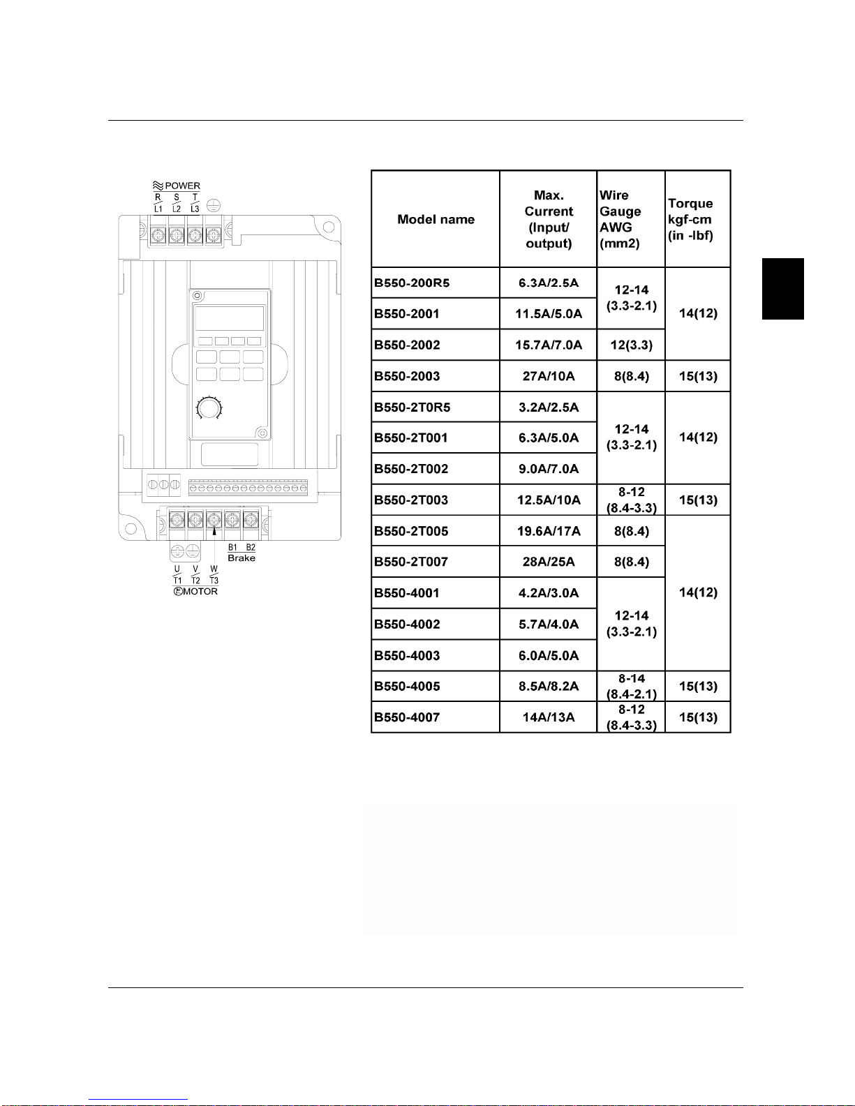
3.4 Main Circuit Wiring
Note: It needs to use the Recognized Ring Terminal to conduct a proper wiring.
Wire Type: 75 oC Copper Only
Model Name
Max.
Current
(input /
output)
Wire
Gauge
AWG
(mm2)
Torque
kgf-cm
(in-lbf)
B550-20R5(1-phase) 6.3A/2.5A
B550-2T0R5(3-phase) 3.2A/2.5A
B550-2001(1-phase) 11.5A/5.0A
VFD007M21B(3-phase) 6.3A/5.0A
12-14
(3.3-2.1)
VFD015M21B(1-phase) 15.7A/7.0A 12 (3.3)
VFD015M21B(3-phase) 9.0A/7.0A 12-14
(3.3-2.1)
14
(12)
VFD022M21A(1-phase) 27A/10A 8 (8.4)
VFD022M21A(3-phase) 15A/10A 8-12
(8.4-3.3)
VFD037M23A 19.6A/17A
8-10
(8.4-5.3)
VFD055M23A 28A/25A 8 (8.4)
15
(13)
VFD007M43B 4.2A/3.0A
12-14
(3.3-2.1)
VFD007M53A 2.4A/1.7A
12-14
(3.3-2.1)
VFD015M43B 5.7A/4.0A
12-14
(3.3-2.1)
VFD015M53A 4.2A/3.0A
12-14
(3.3-2.1)
VFD022M43B 6.0A/5.0A
12-14
(3.3-2.1)
VFD022M53A 5.9A/4.2A
12-14
(3.3-2.1)
14
(12)
VFD037M43A 8.5A/8.2A
8-14
(8.4-2.1)
VFD037M53A 7.0A/6.6A
8-14
(8.4-2.1)
VFD055M43A 14A/13A
8-12
(8.4-3.3)
VFD055M53A 10.5A/9.9A
8-12
(8.4-3.3)
VFD075M43A 23A/18A
8-10
(8.4-5.3)
VFD075M53A 12.9A/12.2A 8-12
(8.4-3.3)
15
(13)
B550 Series sensorless vector frequency drive
3-8
Terminal Explanations
Terminal Symbol Explanation of Terminal Function
R/L1, S/L2, T/L3 AC line input terminals (three phase)
U/T1, V/T2, W/T3 Motor connections
B1 – B2 Connections for Braking Resistor (optional)
Earth Ground
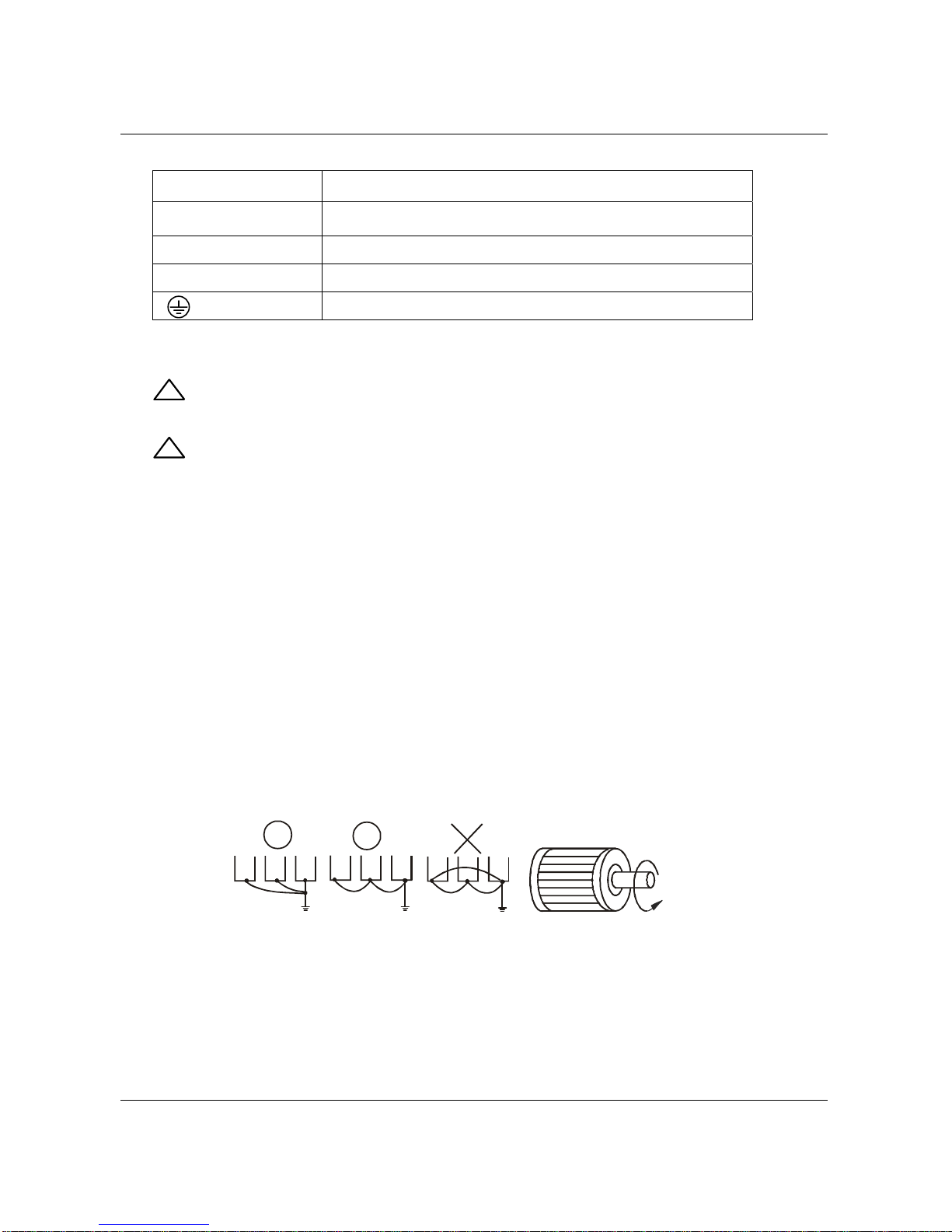
3.5 Wiring Notes: PLEASE READ PRIOR TO INSTALLATION.
1. !CAUTION: Do not connect the AC power to the U/T1, V/T2, W/T3 terminals, as it will
damage the AC drive.
2. !WARNING: Ensure all screws are tightened to the proper torque rating.
3. During installation, follow all local electrical, construction, and safety codes for the country
the drive is to be installed in.
4. Ensure that the appropriate protective devices (circuit breaker or fuses) are connected
between the power supply and AC drive.
5. Make sure that the leads are connected correctly and the AC drive is properly grounded.
6. Use ground leads that comply with AWG/MCM standards and keep them as short as
possible.
7. Multiple B550 units can be installed in one location. All the units should be grounded
directly to a common ground terminal. The B550 ground terminals may also be
connected in parallel, as shown in the figure below. Ensure there are no ground loops.
Forward
running
8. When the AC drive output terminals U/T1, V/T2, and W/T3 are connected to the motor
terminals U, V, and W, respectively, the motor will rotate counterclockwise (as viewed
from the shaft ends of the motor) when a forward operation command is received. To
reverse the direction of motor rotation, switch over any of the two motor leads.
B550 Series sensorless vector frequency drive

3
3-9
9. Make sure that the power source is capable of supplying the correct voltage and required
current to the AC drive.
10. Do not attach or remove wiring when power is applied to the AC drive.
11. Do not inspect components unless inside “CHARGE” lamp is turned off.
12. Do not monitor the signals on the circuit board while the AC drive is in operation.
13. For the single-phase rated AC drives, the AC power can be connected to any two of the
three input terminals R/L1, S/L2, T/L3. Note: This drive is not intended for the use
with single-phase motors.
14. Route the power and control wires separately, or at 90 degree angle to each other.
15. If a filter is required for reducing EMI (Electro Magnetic Interference), install it as close as
possible to AC drive. EMI can also be reduced by lowering the Carrier Frequency.
16. If the AC drive is installed in the place where a load reactor is needed, install the filter close
to U/T1, V/T2, W/T3 side of AC drive. Do not use a Capacitor or L-C Filter
(Inductance-Capacitance) or R-C Filter (Resistance-Capacitance), unless approved by
Delta.
17. When using a GFCI (Ground Fault Circuit Interrupt), select current sensor with sensitivity
of 200mA, and not less than 0.1-second detection to avoid nuisance tripping.
3.6 Motor Operation Precautions
1. When using the AC drive to operate a standard 3-phase induction motor, notice that the
energy loss is greater than for an inverter duty motor.
2. Avoid running a standard induction motor at low speed. Under these conditions, the motor
temperature may rise above the motor rating due to limited airflow produced by the motor’s
fan.
3. When the standard motor operates at low speed, the output load must be decreased.
4. If 100% output torque is desired at low speed, it may be necessary to use a special
“inverter-duty” rated motor.
B550 Series sensorless vector frequency drive

This page intentionally left blank.
B550 Series sensorless vector frequency drive
This manual suits for next models
15
Table of contents
Other Bedford DC Drive manuals

Popular DC Drive manuals by other brands


Siemens
Siemens SINAMICS GM150 Operating instructions & installation instructions

elero
elero SunTop Operating and assembly instructions

Control Techniques
Control Techniques Midi-Maestro user guide

Cutler-Hammer
Cutler-Hammer HV9F10AC-2M0B008 user manual

Piezoconcept
Piezoconcept HS1 Installation and operation manual

TPG
TPG CA Series Operation manual

MAIMAN ELECTRONICS
MAIMAN ELECTRONICS SF6030 user manual

Danfoss
Danfoss VLT Brake Resistor MCE 101 Design guide

Technodrive
Technodrive KR-A535M manual

Aumuller
Aumuller KS2 S2 24V DC R/L Assembly and commissioning instructions

Penn
Penn VFD68BBB Installation instructions manual

BLEMO
BLEMO ER40-K Programming manual