TPG CA Series User manual

VARIABLE FREQUENCY
DRIVE
Operation Manual
CA Series
1

PREFACE
Thank you for using TPG CA series drive. For proper operations and safety
purposes, please do read and follow specific instructions contained in this manual
before using the product.
SAFETY PRECAUTION
Please read this manual thoroughly and pay attention to the safety precautions
marked with “ DANGER ” or “ CAUTION ” before the installation, wiring,
maintenance, or troubleshooting.
Only the qualified personnel may proceed with the installation, wiring, testing,
troubleshooting, or other tasks.
※Qualified Personnel: Must be familiar with the fundamentals, structures,
characteristics, operating procedures, and installation, and this personnel must
read the manual in details and follow the steps of security measures to prevent
possible dangers.
DANGER
User may cause the casualty or serious damages if user
does not abide by the instructions of the manual to execute
the tasks.
CAUTION
User may cause injuries to the people or damage the
equipment if user does not abide by the instructions of the
manual to execute the tasks.
※Although the “ ” mark may indicate minor damages, serious damages or
injuries may be possibly incurred if the caution is not under user’s attention.
Installation
CAUTION
a. The installation shall take place only on top of the metal surface or any material
with the fire resistant. Any place or location of high temperature, moist, oil and
gas, cotton fiber, metal powder and erosive gas shall be avoided.
b. If the product specification indicates IP00 (the protective level of the equipment
structure), any human contact is forbidden at the installation location to avoid the
electric shock. The option of installing AC reactor(ACL) shall be very cautious.
c. Please note the surrounding temperature shall not exceed 50°C when the
installation needs to be placed inside the control panel.
d. For the environment of storage and installation, please follow the instructions of
the environmental conditions illustrated in the sections of the common
specification of CA.
2

Wiring
DANGER
a. Do Not conduct any wiring during the system power ON to avoid the electric shock.
b. R/L1,S/L2,T/L3 are power inputs (electric source terminals) and U/T1,V/T2,W/T3
are drive’s outputs to a motor. Please Do Not connect these input and output
terminals to terminals P♁, N○
-, and PR.
c. Once the wiring is complete, the cover of the drive must be put back and must
seal the drive to avoid other’s accidental contact.
d. The drives have three specifications base on the input power source 100V / 200V
/ 400V, Do Not input the voltage exceed the specifications.
e. The grounding terminal( ) must be exactly grounded. Ground the drive in
compliance with the NEC standard or local electrical code.
f. Please refer to the manual page for the screwing torque of the wiring terminal.
g. Please refer to the national or local electric code for the appropriate spec of the
cords and wires.
h. Please install an appropriate Molded Case Circuit Breaker (MCCB) or Fuse at
each path of power lines to a drive.
i. Please install the thermal relay between the individual motor and the drive when
using one drive to propel several motors.
j. Do Not connect power factor leading capacitor, surge absorber, or
non-three-phase motor to the drive’s U/T1, V/T2, or W/T3 side.
k. AC reactor(ACL) installation is required when the power capacity exceeds
500kVA or 10 times or more than the drive rated capacity.
l. Do Not touch the drive or performing any unwiring actions before drive indicator
light turns off after the power off. Use a multi-meter with the DC voltage stage to
measure the cross voltage between P♁and N○
-terminals (The voltage must
be less than 25V).
m. When the motor do the voltage-proof, insulation testing, unwiring the
U/T1,V/T2,W/T3 terminal of drive at first.
CAUTION
a. The CA series outputs are designed to drive a three-phase induction motor. Do
Not use for single-phase motor or using for other purposes.
b. The main circuit and control circuit must be wired separately; control circuit must
use a shielded or twisted-pair shielded wires to avoid possible interferences.
3
Operation
DANGER
a. Do Not open or remove the cover while power is on or during the drive operation.
Do close up the cover before powering on the drive. Do Not remove the cover
except for wiring or periodic inspection when power off.
b. At the function F3.30= 1 or 3, the drive will automatically restart when the power
is restored. Stay away from the motor and machine.
c. At the function F1.05=0 and F1.00=0 or 1 or 10, the key on the operation
panel is ineffective. Please use an emergency stop switch separately for safe
operations.
d. The drive can produce high frequency outputs. Before adjusting the frequency,
please check the specs of motor carefully to prevent the motor from unexpected
damages.
e. If any of the protective functions have been activated, and the start command is
set to terminal control(F1.00=0 or 1 or 10), first remove the case and check the
all run commands set to OFF. Then press the key to release the alarm.
CAUTION
a. Do Not touch the heat sink or brake resistors due to the high heat.
4

INTRODUCTIONS
Features
a. Special function key(SPEC):
Programmable function key for forward/reverse running, jog speed,
selection of primary/secondary frequency command…etc.
b. Allow RS-485 communication interface control (Modbus RTU
communication protocol).
c. 6 sets of fault records:
Record 4 types of information under fault condition, respectively. (fault
code, output current, DC bus voltage, output frequency)
d. Running hours and supply power time of drive can be saved and
displayed.
e. Group design for the functions ease the function setting and
management.
f. Sequential operation control and PID control function.
g. Provide 8 sets of monitor displays(three of displays can be defined as
another extra displays).
h. Provide PTC sensor setting functions for preventing the motor from
overheating.
i. Energy-saving selection for light-duty load.
j. Auto-torque boost function.
k. Provide 8 preset speeds control.
l. The analog input signal of filter can be adjusted.
m. The response time of digital input signal is adjustable(adjustable dead
band detection).
n. Independent adjustment selection of V, F for analog input signal.
o. Two sets of analog input signals can do addition, subtraction and gain
control.
p. The switching frequency can be adjust between 800Hz ~ 16kHz.
5

Chapter 1 Cautions Before Installation
1-1 Product Verification
The product has passed the strictest quality test before shipped out from the
factory. However, the product might possibly sustain minor damages due to the
impact, shaking, vibration, and other factors during the transportation. Please
make sure to verify the following items after receiving this product. If the
product verification finds anything abnormal, please contact the agent
immediately for the further assistance.
1-1-1 Confirmation of Appearance
1.Check up the drive’s model number is identical with the shipping label on
the carton.
2.Check up the appearance of the drive for any paint chipped off,
smearing, deformation of shape, etc.
3.Check up the nameplate (as below figure) of the drive to verify the
product descriptions with the order specification.
XXXXXXXX
0201-1
3PH AC200-240V1.5A 0.1-400Hz
1PH AC200-240V 3A 50/60Hz
CA-202A
SERIAL NO.
PGM NO.
OUTPUT
INPUT
TYPE Model Number
Input Power Specs
Output Current & Capacity
Sofware Number
Product Serial Number
ISO 9001 IP20
XXXXXXXXX
1-2 Standard Specifications
Model name CA CA-201A CA-202A
Maximum applicable motor (W) 125 200
Rated output capability (VA) 400 600
Rated output current (A) 0.9 1.5
Rated output voltage (V) Three-phase 200~240V
Range of output frequency (Hz) 0.1~400Hz
Power source (ψ, V, Hz) 1Ø, 200~240V , 50 / 60Hz
Input current (A) 1.7 3
Permissible AC power source
fluctuation 176V~264V 50/60Hz /±5%
Overload protection 150% of drive rated output current for 1 min.
Cooling method Nature cooling
Protective structure IP20
Weight / Mass(kg) 384g
6

1-3 Common Specifications
1-3-1 The Features of Control and Operation
Control method ․Voltage vector sinusoidal PWM control(V/F control);
․Switching frequency: 800Hz~16kHz
Range of
frequency setting 0.1~400.00Hz
Resolution
of frequency
setting
․Operation panel: 0.01Hz
․Analog signal: 0.06Hz / 60Hz
Resolution
of output
frequency
0.01Hz
Overload
protection 150% of drive rated output current for 1 minute
DC braking
․Start/stop braking time: 0~60.0sec
․Stop braking frequency: 0.1~60Hz
․Braking ability: 0~150% of rated current
Braking torque Approximately 20%(with the external braking resistor
connected, braking torque is approximately 100%)
V/F pattern
․V/F pattern (2 V/F points)
․Square curve, 1.7th power curve, 1.5th power curve.
․Output voltage adjustment of V/F pattern(Variable voltage
(V) adjustment of V/F pattern for acceleration /
deceleration).
Acceleration/
deceleration time
․0sec(coast to stop), 0.0~3200.0sec(Independent setting of
the acceleration / deceleration).
․The time setting range of the speed acceleration from 0 to
60Hz is 0.015sec ~ 19200000sec(222 days).
Stall prevention
Stall prevention at acceleration / constant speed(the current
level of stall prevention is 30~200%), Stall prevention at
deceleration
Control Characteristics
Other functions
Slip compensation, auto-torque compensation,
auto-adjustment for output voltage stability, auto-operation for
energy-saving, auto-adjustment of switching frequency,
restart after instantaneous power failure, speed tracing,
over-torque detection, DC braking, dynamic braking duty
control, sequential operation control, counter function, PID
control, Modbus communication, jump frequency, holding
frequency, upper/lower limits of output frequency, 16-preset
speeds, acceleration/deceleration switch, S-curve
acceleration/deceleration, fan control, parameters
duplication, overload detection
7
Start method
Command the drive via 3 programmable multi-function input
terminals(X1~X3): Forward command / Reverse command,
3-wire start/stop control, 8 sets preset speed control.
4 programmable input terminals: X1~X3
Response time (1~255, unit: 1ms)
Multi-function
inputs Refer to the chapter of function setting description for
F5.19~F5.21.
1 set of analog inputs: AI(DC 0~10V / 2~10V or DC 0~20mA /
4~20mA)
Analog filter (0~255, unit: 5ms), the dead band of
Analog frequency, gain and bias are adjustable.
Input
Analog inputs
Refer to the chapter of function setting description for F5.01,
F5.02.
1-set programmable output terminal: Ta / TcMulti-function
outputs Refer to chapter of function setting description for F5.26.
1 set of analog output: FM(DC 0~10V / 2~10V or DC 0~20mA
/ 4~20mA)
The gain and bias are adjustable.
Operation Characteristics
Output
Analog
outputs Refer to the chapter of function setting description for
F5.12~F5.15.
Atmosphere Non-corrosive or non-conductive, or non-explosive gas or
liquid, and non-dusty
Surrounding
temperature
-10°C (14°F) ~ +50°C (122°F) (Non-freezing and
non-condensing)
Storage
temperature -20°C (-4°F) ~ +60°C (149°F)
Relative humidity 90% RH or less (No-condensing atmosphere)
Vibration Less than 5.9m/sec² (0.6G)
Altitude Less than 1000m (3280 ft.)
E
n
v
i
r
o
n
m
e
n
t
8

Chapter 2 Installation and Confirmation
2-1 Basic Equipment
The drive needs the several components for the conjunctive operation. These
components are called “basic equipment”, listed in the following:
2-1-1 Power Source: The voltage with three-phase or single-phase of
the power source must meet the drive specifications.
2-1-2 MCCB or NFB: MCCB (Molded Case Circuit Breaker) or NFB (No Fuse
Breaker) can withstand the inrush current at instant power-on and
providing the overload and over-current protection to the drive.
2-1-3 Drive: The rated current of motors are different for the different pole or
rated voltage. Please base on the rated voltage and rated current of
motor to select drive. Do not select the drive only base on the horse
power specification of motor. (please refer to the lists of standard
specifications of drives)
2-1-4 Motor: The specifications of motor are determined from the
requirement. Please be cautious to the motor rated current that must
not exceed the drive current.
Note: CA is only used for three-phase induction motor control, and must not be used
for single-phase motor.
2-2 Environmental Conditions
For the safe operation of the drive, please be cautious to the environmental
conditions where the drive is going to be installed.
2-2-1 AC Power: AC power input must be complied with the AC power input
specification of the drive.(see CA standard specifications)
2-2-2 Location: Due to the heat dissipating requirement during the drive
operation, the drive must keep enough space for heat dissipation. Please
keep the least clearance space when installation. (shown as below
figure):
10cm
5cm
10cm
5cm
9

2-2-3 Specifications of Associated Accessories: The specifications of the
accessories must be according to the specifications of the drive.
Otherwise, the drive will be damaged and the lifetime of the drive will be
shorten.
Do Not add any power factor leading capacitor(RC, LC or other capacitance
component) between the drive and motor to avoid any accidents.
2-2-4 Cleaning of Environment: The installed location of drive must consider
the ventilation, cleanliness and moisture.
2-2-5 Operator: Only the qualified personnel can perform the operation and
troubleshooting.
10

2-3 Descriptions of Terminal and Wiring Diagram
2-3-1 Wiring Diagram
2-3-2 Wiring Diagram
a. Main Circuit Connection
Type Symbol Function Description
Power
Source L1,L2
AC power
source input
terminals
Single-phase; sinusoidal power
source input terminal.(200~240V)
Motor U,V,W
Drive outputs to
motor terminals
The terminals output three phase
variable frequency and voltage to
motor.
Grounding
Grounding
terminal
Ground the drive in compliance
with the NEC standard or local
electrical code.
b. Control Terminals
Type Symbol Function Description
X1 Multi-function
input terminal 1
X2 Multi-function
input terminal 2
Input
terminals
X3 Multi-function
input terminal 3
Short the terminal with COM and
set the function F5.19~F5.21.
Y1 Multi-function
output terminal 1
Short the terminal with COM and
set the function F5.26
Output
terminals COM Input/output
common terminal
The common terminal of input
control signal.
V+
Power terminal for
analog input
control
12V position: Maximum supplied
current is 20mA.
Control power
VI Analog signal
input terminal DC 0~10V
11

GND
Common terminal
for analog input
control
Common terminal for control
power (12V/24V) and analog input
terminal (AI)
c. Modbus Port (RJ-45)
Type Pin Function Description
1 Communication transmission
terminal (DX+)
2 Communication transmission
terminal (DX-)
Differential input of
RS-485
*Note 1
Modbus (RS-485)
communication only uses
pin1, 2.
Modbus
(RS-485)
3-8 Reserved Reserved
Note 1: The terminal resistor(100Ω) selection is set by DSW1(default: ON)
8-pin telephone cable: The cable length must be within 5 meters.
Network cable(AMP): The cable length can be over 5 meters (the longest length
is 100 meters)
12
Chapter 3 The Setting of Operation Panel & Remote Controller
3-1 The Operation of the Operation Panel and Monitor Mode
3-1-1 The Operation of Operation Panel
The operation of the operation panel includes fault messages and three
modes. The switching methods are shown as below figure:
The operation steps are shown in the below table (by default setting)
Operation Steps Display
1.Start the drive and enter the main display.
2.Press key and enter the function setting mode.
3.Press key and enter the parameter setting mode.
4.Press key and return to the function setting mode.
5.Press PROG key and return to the monitor mode.
Fault message display:
Operation Steps Display
The fault message displayed during the drive operation
1.After the error is troubleshooted, pressing key to
clear the fault message and then return to the monitor
mode.
13

3-1-2 Monitor Mode
There are eight monitor modes can be selected in the monitor mode. User
can determine one of eight monitor modes as the main display on the
operation panel. And the monitor mode can be switched as shown in below
figure:
Hz
V
A
CRG
RUN
Hz
V
A
CRG
RUN
Hz
V
A
CRG
RUN
Hz
V
A
CRG
RUN
Display 1
(Output Frequency)
Display 2
(Frequency Command)
Display 3
(Output Voltage)
Display 8
(Default:Motor Speed(RPM))
Hz
V
A
CRG
RUN
Display 4
(DC bus Voltage)
Hz
V
A
CRG
RUN
Hz
V
A
CRG
RUN
Hz
V
A
CRG
RUN
Display 7
(Default:Temperature of Heat Sink)
Display 6
(Default:Terminal Status)
Display 5
(Output Current)
Enter monitor mode
FUN C
DATA
FUNC
DATA
FUN C
DATA
FUN C
DATA
FUN C
DATA
FUN C
DATA
FUN C
DATA
FUNC
DATA
The descriptions of monitor modes are shown in the below table(example by default
setting)
Display Descriptions Display
Display 1 Output frequency (Hz, CRG: ON)
Display 2 Frequency command (Hz, CRG: ON)
Display 3 Output voltage (V, CRG: ON)
Display 4 DC bus voltage (V, CRG: ON)
Display 5 Output current (A, CRG: ON)
Display 6 Terminal status (Hz, V, CRG, RUN: ON)
Display 7 Heat sink temperature (V, A, CRG: ON)
Display 8 Motor speed(RPM) (Hz, A, CRG: ON)
a. User can select the main display from eight monitor displays and switch to another
monitor displays by FUNC
DATA key under monitor mode. The selection of monitor
displays can be set from F1.08.
b. User can determine one of the displays to be the main display according to the
demand. If the user does not change the display back the main display after the
setting is completed, the drive will automatically switch back to the main display
after the operation panel is idle over 3 min.
c. The display 6~8 are defined by F1.09~F1.11
14
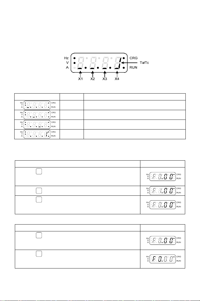
3-1-3 The Status of Multi-function Terminals
The default setting of “Display 6” is the status of multi-function input
terminals and the definition of each segment on the seven-segment display
for 4 digits is shown as below figure:
The definition of display shown in the below table:
Display Terminal Status description
X1 Multi-function input terminal “X1” is active.
X2 Multi-function input terminal “X2” is active.
X3 Multi-function input terminal “X3” is active.
Y1 Multi-function input terminal “Y1” is active.
3-1-4 The Function Setting Mode
a.The selection of function group:
Operation Steps Display
1.Press PROG key to enter function group setting mode
under monitor mode and the function group in the display
will be flashing.
2.Press ▲key to increase the function group number.
3.Press ▼key to decrease the function group number.
See “Chapter 4 Parameter List” for the setting range of
function groups.
b.The switch of function group and function number:
Operation Steps Display
1.Press << key to switch the function number setting
mode to function group setting mode when function group
is flashing.
2.Press << key to switch the function group setting mode
to function number setting mode when function number is
flashing.
15

c.The selection of function number:
Operation Steps Display
1.Press << key to switch to the function number setting
mode after the function group is selected. And the
function number is flashing.
2.Press ▲key to increase the function number.
3.Press ▼key to decrease the function number. See
“Chapter 4 Parameter List” for the setting range of
function numbers.
Note: The grey-color digits in above tables represent the flashing of the digits.
3-1-5 Parameter Setting Mode
The setting range of parameter is according to the function. The operation
steps are shown in the below table:
Operation Steps Display
1.The function setting mode: example F2.17(output
frequency).
2.Press FUNC
DATA key in the function setting mode and enter
parameter setting mode.
3.Press << key to shift the digit; Example: Shift the
number to the last digit after the decimal point.
4.Press ▲key to increase 0.1 to the output frequency.
5.Press ▼key to decrease 0.1 to the output frequency.
6.Press FUNC
DATA key and return to function setting mode.
a.The digit of parameter value is flashing after the parameter value is changed.
(grey-color digits in above table means digit flashing)
b.The setting range of F2.17 is 0.00~400.00Hz
16

3-1-6 The Operation in the Monitor Mode
Frequency command, motor speed(RPM), machine speed(MPM) are
changeable under monitor mode. For example of frequency command
change, the setting steps are shown in the following table.
The operation steps are shown in the below table:
Operation Steps Display
1.In the monitor mode, the display is shown as right.
2.Press << key to shift the digit of frequency command.
3.Press << key to shift the digit of frequency command.
Example: Change the digit of decimal value.
4.Press ▲key to increase 1 to the frequency command.
5.Press ▼key to decrease 1 to the frequency command.
6.Press FUNC
DATA key to save the setting value within 5sec,
when completing setting of the rotation speed.
Note: grey-color digits in above table means digit flashing.
a.Use ▲or ▼key to control the rotation speed in the monitor mode.
b.Press FUNC
DATA key to save the setting value within 5sec(the setting value is
flashing), when the required rotation speed is set. If the setting value is not
saved, the display will return to the monitor mode after 5sec and save the
value automatically after 3 min. If the saving of the setting value is not
completed and drive immediately powers off within 3 min, the setting value will
recover to the original value before setting.(see F1.07 for the setting).
3-1-7 Start/Stop of the Drive
Press RUN and STOP
RESET key to control the output of drive. Shown as below:
3-1-8 SPEC Programmable Special function key(SPEC) for forward/reverse
(grey-color digits in above table means digit flashing)
17

18
3-1-9 Save and Restore the Setting Value.
a.The operation steps of saving drive function setting are shown in the below table:
Operation Steps Display
1.Press PROG key and enter the function setting mode.
2.Press << key and switch to the function number setting
mode.
3.Press ▼key to select F0.20.
4.Press FUNC
DATA key and enter the parameter setting mode.
5.Press ▲key and select the “SAv”.
6.Press FUNC
DATA key to save settings. The display of operation
panel will display “End” after 2sec.
7.After the panel displays ”End” for 1 sec, the display
automatically returns to the function setting mode.
8.Press PROG key and return to the monitor mode
(frequency command).
b.The operation steps of resuming drive function setting are shown in the below table:
Operation Display
1.Press PROG key and enter the function setting mode.
2.Press << key and switch to the function number setting
mode.
3.Press ▼key to select F0.20.
4.Press FUNC
DATA key to enter the parameter setting mode.
5.Press ▲key and select the “rES”.
6.Press FUNC
DATA key to save the setting. The panel will display
“End” after 2sec.
7.After the panel displays ”End” for 1 sec, the display
automatically returns to the function setting mode.
8.Press PROG key and return to the monitor mode
(frequency command).

Chapter 4 Parameter List
Group List(Factory Setting: F0.18=0)
brief version function
(F0.18=0)
detail function
(F0.18=1)
Group Function Group Function
F0System
ParametersF0
Systemstatus
Parameterlocking
Passwordprotection
Powersourcevoltagesetting
F1
Startcommandselection
Frequencycommand
selection
Maindisplayselection
SPECkeysetting
Switchingfrequency
Stopmode
F1
Startcommandselection
Frequencycommandselection
Maindisplayselection
SPECkeysetting
Switchingfrequency
Stopmode
F2 Frequency Parameters F2 Frequency
Parameters
Presetspeed
Multi‐acceleration/deceleratio
ntime
V/Fpatternsetting
Upper/lowerlimitsofoutput
frequency
F4 Control
Parameters
F3
Control
Parameters
Holdingfrequencyandtime
Stallpreventionsetting
Motorslipcompensation
Automaticboostvoltagerange
Currentoscillationprevention
Speedtracing
Currentcompensation
F5 Protection
ParametersF4 Protection
Parameters
Groundingfaultprotection
Driveoverloadprotection
Motoroverloadprotection
Driveoverheatprotection
Overload protection setting
F5Multi‐function
parameters
Analoginput
Analogoutput
Multi‐functioninput
Multi‐functionoutput
UP/DOWNsetting
Countingmode
Frequencydetection
F6Special
parameters
Sequentialoperationcontrol
Modbuscommunication
19

F0 System Parameters
Func. Name Descriptions Range of
Setting Unit Factory
Setting Note
F0.00 Drive
Information
0: Software version
1: Drive model number
2: Drive rated current
3: Drive running hours
4: Drive supply power time
5: Software checksum code
── ─
F0.01 Parameter
Lock
0: Parameters are changeable
1: Parameters are locked 0, 1 ─0
F0.02 Reserved Reserved ── ─ *Note 9
F0.03 Reserved Reserved ── ─ *Note 9
F0.04 Reserved Reserved ── ─ *Note 9
100.0~120.0
*Note 3
110.0
*Note 3
190.0~240.0
*Note 4
220.0
*Note 4
F0.05 Power
Source
The value of setting according to
the actual power source
340.0~480.0
*Note 5
0.1V
380.0
*Note 5
*Note 9
F0.08 Fault
Record 1 ── ─ *Note 9
F0.09 Reserved ── ─ *Note 9
F0.10 Reserved ── ─ *Note 9
F0.11 Reserved ── ─ *Note 9
F0.12 Reserved ── ─ *Note 9
F0.13 Reserved
0: Fault code
1: Output current at drive fault
2: DC bus voltage at drive fault
3: Output frequency at drive fault
── ─ *Note 9
F0.18 Function 0:brief 1:detail function 0,1 ─0
F0.19 Reserved
Reserved
*Note 9
0: Disable
CLF: Clear fault records
dF60: Default the factory setting
of 60Hz
dF50: Default the factory setting
of 50Hz
SAv: Store setting
F0.20 Default
Setting
rES: Resume setting
──0
The color as means functions can be set during the operation.
20
This manual suits for next models
2
Table of contents
Popular DC Drive manuals by other brands

Epson
Epson S1F76680 Technical manual

Rhymebus
Rhymebus RM6 Series Operation manual

Exhausto
Exhausto NFO Sinus Optimal Quick installation guide

Danfoss
Danfoss VLT AQUA Drive FC 202 operating guide

Rockwell Automation
Rockwell Automation Allen-Bradley PowerFlex 525 Product information

Festo
Festo CMMT-ST-SW Original instructions


ABB
ABB ACQ580-04 Hardware manual

GFA
GFA ELEKTROMAT SI 60.24-55,00 installation instructions

Danfoss
Danfoss vlt aqua operating instructions

TIME LED
TIME LED 781234 Installation and operating instructions

Altec Lansing
Altec Lansing HF DRIVER - REPAIR Repair

Danfoss
Danfoss VLT HVAC Basic Drive FC 101 quick guide