Trane CVHE User manual

AFDH E-Frame Upgrade Adaptive
Frequency Drive
For Tracer® AdaptiView™ Centrifugal Chiller
Controllers
Installation Instructions
May 2020 AFDH-SVN004C-EN
Direct Mount Transition Mount LiquiFlo Mount
Models: CVHE, CVHF, AFDH
Design Sequence:F0
SAFETY WARNING
Only qualified personnel should install and service the equipment. The installation, starting up, and servicing of
heating, ventilating, and air-conditioning equipment can be hazardous and requires specific knowledge and training.
Improperly installed, adjusted or altered equipment by an unqualified person could result in death or serious injury.
When working on the equipment, observe all precautions in the literature and on the tags, stickers, and labels that are
attached to the equipment.

© 2020 Trane AFDH-SVN004C-EN
Introduction
Read this manual thoroughly before operating or servicing
this unit.
Warnings, Cautions, and Notices
Safety advisories appear throughout this manual as
required. Your personal safety and the proper operation of
this machine depend upon the strict observance of these
precautions.
Important Environmental Concerns
Scientific research has shown that certain man-made
chemicals can affect the earth’s naturally occurring
stratospheric ozone layer when released to the
atmosphere. In particular, several of the identified
chemicals that may affect the ozone layer are refrigerants
that contain Chlorine, Fluorine and Carbon (CFCs) and
those containing Hydrogen, Chlorine, Fluorine and
Carbon (HCFCs). Not all refrigerants containing these
compounds have the same potential impact to the
environment. Trane advocates the responsible handling of
all refrigerants-including industry replacements for CFCs
and HCFCs such as saturated or unsaturated HFCs and
HCFCs.
Important Responsible Refrigerant
Practices
Trane believes that responsible refrigerant practices are
important to the environment, our customers, and the air
conditioning industry. All technicians who handle
refrigerants must be certified according to local rules. For
the USA, the Federal Clean Air Act (Section 608) sets forth
the requirements for handling, reclaiming, recovering and
recycling of certain refrigerants and the equipment that is
used in these service procedures. In addition, some states
or municipalities may have additional requirements that
must also be adhered to for responsible management of
refrigerants. Know the applicable laws and follow them.
The three types of advisories are defined as follows:
WARNING Indicates a potentially hazardous
situation which, if not avoided, could
result in death or serious injury.
CAUTIONsIndicates a potentially hazardous
situation which, if not avoided, could
result in minor or moderate injury. It
could also be used to alert against
unsafe practices.
NOTICE Indicates a situation that could result in
equipment or property-damage only
accidents.
WARNING
Proper Field Wiring and Grounding
Required!
Failure to follow code could result in death or serious
injury. All field wiring MUST be performed by qualified
personnel. Improperly installed and grounded field
wiring poses FIRE and ELECTROCUTION hazards. To
avoid these hazards, you MUST follow requirements for
field wiring installation and grounding as described in
NEC and your local/state electrical codes.
WARNING
Personal Protective Equipment (PPE)
Required!
Failure to wear proper PPE for the job being undertaken
could result in death or serious injury. Technicians, in
order to protect themselves from potential electrical,
mechanical, and chemical hazards, MUST follow
precautions in this manual and on the tags, stickers,
and labels, as well as the instructions below:
• Before installing/servicing this unit, technicians
MUST put on all PPE required for the work being
undertaken (Examples; cut resistant gloves/sleeves,
butyl gloves, safety glasses, hard hat/bump cap, fall
protection, electrical PPE and arc flash clothing).
ALWAYS refer to appropriate Safety Data Sheets
(SDS) and OSHA guidelines for proper PPE.
• When working with or around hazardous chemicals,
ALWAYSrefertotheappropriateSDSandOSHA/GHS
(Global Harmonized System of Classification and
Labeling of Chemicals) guidelines for information on
allowable personal exposure levels, proper
respiratory protection and handling instructions.
• If there is a risk of energized electrical contact, arc, or
flash, technicians MUST put on all PPE in accordance
with OSHA, NFPA 70E, or other country-specific
requirements for arc flash protection, PRIOR to
servicing the unit. NEVER PERFORM ANY
SWITCHING, DISCONNECTING, OR VOLTAGE
TESTING WITHOUT PROPER ELECTRICAL PPE AND
ARC FLASH CLOTHING. ENSURE ELECTRICAL
METERS AND EQUIPMENT ARE PROPERLY RATED
FOR INTENDED VOLTAGE.

Introduction
AFDH-SVN004C-EN 3
Copyright
This document and the information in it are the property of
Trane, and may not be used or reproduced in whole or in
part without written permission. Trane reserves the right
to revise this publication at any time, and to make changes
to its content without obligation to notify any person of
such revision or change.
Trademarks
All trademarks referenced in this document are the
trademarks of their respective owners.
Revision History
•Updated cover page figure.
•Updated Model Number Descriptions chapter.
•Updated for HUB document numbers in General
Information chapter.
•Updated mounting drawings in Pre-Installation
chapter.
•Updated unit dimensional drawings in AFDH Drive
Package Specifications
•Updated steps for Direct Mount Drive to Replace
Direct Mount Starter and mounting installation
figures in Installation chapter.
•Updated Trane default settings table in AFDH
Startup Procedure chapter.
•Updated job specific settings and Trane default
settings tables in AFDH Startup Procedure.
•Part number updated in table for Air filter in
Recommended Periodic Maintenance and
Inspection chapter.
WARNING
Follow EHS Policies!
Failure to follow instructions below could result in
death or serious injury.
• All Trane personnel must follow the company’s
Environmental, Health and Safety (EHS) policies
when performing work such as hot work, electrical,
fall protection, lockout/tagout, refrigerant handling,
etc. Where local regulations are more stringent than
these policies, those regulations supersede these
policies.
• Non-Trane personnel should always follow local
regulations.
WARNING
Refrigerant under Positive Pressure!
Failure to follow instructions below could result in an
explosion which could result in death or serious injury
or equipment damage. System contains oil and
refrigerant and may be under positive pressure. Recover
refrigerant to relieve pressure before opening the
system. See unit nameplate for refrigerant type. Do not
use non-approved refrigerants, refrigerant substitutes,
or refrigerant additives.
NOTICE
Stand-Mounted AFDH Supported by
Equipment Room Floor!
Trane assumes no responsibility for equipment damage
caused by the installation of an AFDH drive version that
is specified as being incorrect for the application. A
stand-mounted version of an AFDH drive is designed to
be rigidly supported by the equipment room floor.
Therefore, a stand-mounted AFDH drive is not
recommended for use with a chiller that is equipped
with spring-type vibration or seismic isolators. Trane
recommends using a remote floor-mounted AFDH drive
in this application.
NOTICE
Incorrect Application! Adapting a Floor
Stand Kit to an E-Frame AFDH!
The smallest model E-Frame drive weighs 1203 pounds.
Any attempt to adapt the 50689890010 Floor Stand Kit
to an E-Frame model AFDH drive will be considered an
unsupported field modification to the drive unit design.
Trane assumes no responsibility for the equipment
damage caused by a stress or fatigue failure of the floor
stand kit due to any use outside of its intended
application.

4 AFDH-SVN004C-EN
Table of Contents
Model Number Descriptions .............. 5
Unit Model Number .................... 5
Nameplates ............................. 7
General Information ..................... 8
Other Literature Required Before Ordering or
Installing an AFDH Upgrade ............. 8
Pre-Installation .......................... 9
Confirming the AFDH Package can be Properly
Installed .............................. 9
Installation Considerations for Unit-Mounted
AFDH Drives ........................ 9
Confirm Chiller Controller System Compatibil-
ity with AFDH Drive ................... 12
Equipment Room Ambient Temperature and
Environmental Considerations ......... 12
Chiller Upgrades ..................... 12
Electrical Cable Size Specifications for AFDH
Drives ............................... 13
Requirements for Installation Technicians 14
Tools Required ....................... 14
Miscellaneous Field-Provided Material .. 14
Recommended Rigging and Lifting Proce-
dures for AFDH Drive Units ............ 15
Unit Lifting Points ................... 15
Alternative Lifting Method ............ 16
Center of Gravity Reference (FEA Method)
16
AFDH Drive Package Specifications ...... 18
Transition Mount Unit Dimensions ...... 19
LiquiFlo 1.0/1.5 Frame 4 Unit Dimensions 20
Drive Unit Weights and Heat Rejection .. 22
E-Frame Drive Unit Components ....... 23
Drive Unit Component Parts Housed within
the Custom Enclosure ............... 23
Additional Hardware Shipped with Tracer®
AdaptiView™ AFDH Packages ......... 32
Installation ............................. 34
Removal of Electrical Connections to the Ex-
isting Starter ......................... 34
Mechanical Removal of Existing Unit-Mount-
ed Starter ............................ 34
Mechanical Removal of Existing Unit-Mount-
ed LiquiFlo 1.0/1.5 Adaptive Frequency Drive
35
Mechanical Installation of a Unit-Mounted
AFDH E-Frame ........................36
Transition Mount Drive to Replace Transition
Mount Starter .......................36
LiquiFlo Frame 3 Drive Replacement .....38
Direct Mount Drive to Replace Direct Mount
Starter ...............................41
Linkage Bracket Installation for a Unit- Mount-
ed Direct Mount E-Frame ...............43
Circuit Breaker Adjustment to Accommodate
Power Line Wiring ...................45
LiquiFlo 1.0/1.5 Frame 4 Replacement ....45
Electrical Installation (All AFDH Models) ..46
Install Shorting Buss Bars .............46
Input Power Wire Installation ..........47
Grounding AFDH Cabinet .............48
Output Wiring from the AFDH to the CTV Mo-
tor ................................48
Routing of Control Wiring to AFDH Cabinet .
49
Control Wiring Connections (Tracer® Adap-
tiView™ Model AFDH Only) .............49
Required Reprogramming of Tracer® Adap-
tiView™ Controls. .....................50
Reprogramming Factory Installed Tracer®
AdaptiView™ Controls (CTV Simplex Firm-
ware) ..............................50
AFDH Startup Procedure .................51
Drive Settings .........................51
TR200 Drive Configuration ..............52
Troubleshooting .........................53
Startup Test Log .........................54
Recommended Periodic Maintenance and In-
spection ................................55
Inspection Frequency ..................55
Visual Inspection—Power Removed ......55
Operational Inspection—Power Applied ..55
Air Filter ..............................55
Wiring Diagram Matrix ...................56

AFDH-SVN004C-EN 5
Model Number Descriptions
Unit Model Number
For service purposes, Trane®Model
AFDH Air-Cooled drive upgrade
packages are assigned a multiple
character alphanumeric model
number that precisely identifies each
unit.
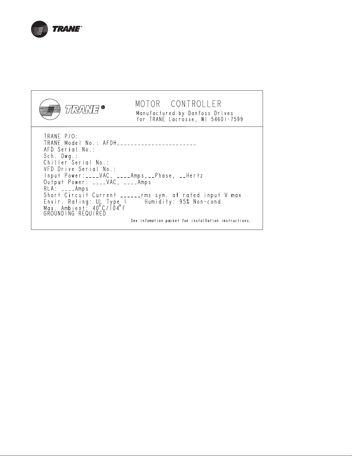
An explanation of the identification
code that appears on the unit
nameplate is shown below. Use of
the service model number will
enable the owner/operator, installing
contractors, and service technicians
to define the operation, components,
and options for any specific unit.
Refer to the model number printed
on the nameplate when ordering
replacement parts or requesting
service.
Digits 1, 2, 3 — Air Cooled
Adaptive Frequency Drive
AFD =Air Cooled Adaptive Frequency
Drive
Digit 4 — Development
Sequence
H
Digits 5, 6, 7, 8 — Starter Size
(Performance RLA rating)
Performance RLA = Performance RLA
Digit 9 — Chiller Voltage
D = 380V 60 Hz 3 Phase
E = 440V 60 Hz 3 Phase
F = 460V 60 Hz 3 Phase
G = 480V 60 Hz 3 Phase
H = 575V 60 Hz 3 Phase
J = 600V 60 Hz 3 Phase
R = 380V 50 Hz 3 Phase
T = 400V 50 Hz 3 Phase
U = 415V 50 Hz 3 Phase
Digits 10, 11— Design Sequence
** = Factory assigned
Digit 12 — New Short Circuit
Rating
C = 35K Short Circuit
A = 65K Short Circuit
B = 100K Short Circuit
Digits 13, 14 — Maximum RLA
1B = 190 Maximum RLA - 60 Hz
(460/480)
1C = 240 Maximum RLA - 60 Hz
(460/480)
0C = 302 Maximum RLA - 60 Hz
(460/480)
0D = 361 Maximum RLA - 60 Hz
(460/480)
0E = 443 Maximum RLA - 60 Hz
(460/480)
1A = 535 Maximum RLA - 60 Hz
(460/480)
0H = 590 Maximum RLA - 60 Hz
(460/480)
0J = 678 Maximum RLA - 60 Hz
(460/480)
0K = 730 Maximum RLA - 60 Hz
(460/480)
01 = 780 Maximum RLA - 60 Hz
(460/480)
02 = 890 Maximum RLA - 60 Hz
(460/480)
1D = 131 Maximum RLA - 60 Hz
(575/600)
1E = 155 Maximum RLA - 60 Hz
(575/600)
1F = 192 Maximum RLA - 60 Hz
(575/600)
0L = 242 Maximum RLA - 60 Hz
(575/600)
0M = 290 Maximum RLA - 60 Hz
(575/600)
0N = 344 Maximum RLA - 60 Hz
(575/600)
0P = 400 Maximum RLA - 60 Hz
(575/600)
0R = 450 Maximum RLA - 60 Hz
(575/600)
0T = 500 Maximum RLA - 60 Hz
(575/600)
0U = 570 Maximum RLA - 60 Hz
(575/600)
0V = 630 Maximum RLA - 60 Hz
(575/600)
03 = 729 Maximum RLA - 60 Hz
(575/600)
04 = 850 Maximum RLA - 60 Hz
(575/600)
1G = 212 Maximum RLA - 50 Hz
(380/400)
1H = 260 Maximum RLA - 50 Hz
(380/400)
0W = 315 Maximum RLA - 50 Hz
(380/400)
0X = 395 Maximum RLA - 50 Hz
(380/400)
0Y = 480 Maximum RLA - 50 Hz
(380/400)
0Z = 588 Maximum RLA - 50 Hz
(380/400)
05 = 658 Maximum RLA - 50 Hz
(380/400)
06 = 745 Maximum RLA - 50 Hz
(380/400)
07 = 800 Maximum RLA - 50 Hz
(380/400)
08 = 880 Maximum RLA - 50 Hz
(380/400)
09 = 990 Maximum RLA - 50 Hz
(380/400)
Digit 15 — Chiller Control Type
3 = AdaptiView Controls Only
Digit 16 — Agency Listing
1 = UL Listing (includes Canada and
California)
0 = No Listing
Digit 17 — AFD Type
C = NEMA 1 Upgrade Enclosure
Digit 18 — Mounting Type
C = Remote Mount
A = Transition Mount
L = LiquiFlo Mount
P = Direct Mount 440E, 5000, 5800
Frame
T = Direct Mount 400 Frame
Digit 19 — AFD to Motor
Transition
0 = No Motor Transition
A = 6" Sheetmetal Transition
C = 12" Sheetmetal Transition
B = 18" Sheetmetal Transition
Digit 20 — Frame Size
D = D - Frame
E = E - Frame
Digit 21 — Evaporator Shell Size
0 = For Transition, LiquiFlo, or
Remote
5 = 050S Short Evaporator Shell
6 = 050L Long Evaporator Shell
7 = 080S Short Evaporator Shell
8 = 080L Long Evaporator Shell
A = 142E Extended Evaporator Shell
B = 142M Medium Evaporator Shell
C = 142L Long Evaporator Shell
E = 210L Long Evaporator Shell
Digit 22 — Replacement Bracket
for LF1.0/LF1.5
0 = No Bracket Needed
1 = Replacement Bracket Kit Needed
Digit 23
0
Digit 24 — Lug Sizes
0 = All Applicable Lugs
N = Two Wire 3/0 - 250 KCmil
B = Two Wire 400 - 500 KCmil
C = Four Wire 4/0 - 400 KCmil
D = Three Wire 4/0 - 400 KCmil
E = Three Wire 500 - 750 KCmil
F = Two Wire 2/0 - 250 KCmil
G = One Wire 2/0 - 500 KCmil
H = Three Wire 3/0 400 KCmil
J = Two Wire 500 - 750 KCmil
K = One Wire 200 - 500 KCmil
L = Two Wire 3/0 - 350 KCmil
M = Two Wire 2AWG - 500 KCmil
P = Three Wire 4/0 - 500 KCmil
Q = Four Wire 4/0 - 500 KCmil
R = Four Wire 3/0 - 400 KCmil
Digit 25 — Jumper Bar Kit
0 = No Jumper Bars Required
A = Bar Kit 1 (distance between holes
5.385 and dia. .812)
B = Bar Kit 2 (distance between holes
5.831 and dia. .812)
C = Bar Kit 3 (distance between holes
6.103 and dia. .812)
D = Bar Kit 4 (distance between holes
6.103 and dia. 1.187)
E = All Bars Included
Digits 26, 27 — Design Specials
00 = No Design Special

Model Number Descriptions
6 AFDH-SVN004C-EN
Digits 28, 29 — Harmonic
Attenuation
00 = No Attenuation
Line Reactors
0A = Line /Load Reactor, 0.125mH, 320
Amps, NEMA1
0B = Line /Load Reactor, 0.105mH, 400
Amps, NEMA1
0C = Line /Load Reactor, 0.085mH, 500
Amps, NEMA1
0D = Line /Load Reactor, 0.065mH, 600
Amps, NEMA1
0E = Line /Load Reactor, 0.048mH, 750
Amps, NEMA1
0F = Line /Load Reactor, 0.042mH, 850
Amps, NEMA1
0G = Line /Load Reactor, 0.040mH, 900
Amps, NEMA1
0H = Line /Load Reactor, 0.0038mH,
1000 Amps, NEMA1
Advanced Filter
1A = Advanced Filter -208 Amp free
standing harmonic filter
1B = Advanced Filter -240 Amp free
standing harmonic filter
1C = Advanced Filter -320 Amp free
standing harmonic filter
1D = Advanced Filter -403 Amp free
standing harmonic filter
1E = Advanced Filter -482 Amp free
standing harmonic filter
1F = Advanced Filter -636 Amp free
standing harmonic filter
1G = Advanced Filter -786 Amp free
standing harmonic filter
1H = Advanced Filter -850 Amp free
standing harmonic filter
1J = Advanced Filter -1000 Amp free
standing harmonic filter
1K = Advanced Filter -1200 Amp free
standing harmonic filter
1L = Advanced Filter -208 Amp free
standing harmonic filter
1M = Advanced Filter -208 Amp free
standing harmonic filter
1N = Advanced Filter -208 Amp free
standing harmonic filter
1P = Advanced Filter -208 Amp free
standing harmonic filter
1Q = Advanced Filter -208 Amp free
standing harmonic filter

AFDH-SVN004C-EN 7
Nameplates
A nameplate is installed on each AFDH Air-Cooled Drive
unit. Always provide the model number and serial number
that is printed on this nameplate when making warranty
inquiries, ordering parts, or ordering literature for the unit.
Figure 1. Nameplate

8 AFDH-SVN004C-EN
General Information
This manual describes the procedures required to install
NEMA 1 AFDH Air-Cooled Adaptive Frequency Drive
package in place of existing direct mount starter,
Transition mount starter, and LiquiFlo 1.0/1.5 drive on
Trane CVHE, CVHF, CVHG model centrifugal chillers and
retrofit LiquiFlo1.0/1.5 drives.This only applies to chillers
with Tracer® AdaptiView™ controller.
E-Frame AFDH can be ordered in a unit-mounted
configuration. Voltage options include 380/400V, 460/
480V, and 575/600V.
The E-Frame units can be equipped with drive rating:
• 658 amps, 745 amps, 800 amps, 880 amps, or 990 amps
for 380V/400V.
• 590 amps, 678 amps, 730 amps, 780 amps, or 890 amps
for 460V/480V.
• 450 amps, 500 amps, 570 amps, 630 amps, 730 amps,
or 850 amps for 575V/600V.
Note: The factory installed Tracer CH530 chiller controller
system will not support an AFDH Air-Cooled
Adaptive Frequency drive. The controller system
must be upgraded to Tracer® AdaptiView™ before
an AFDH upgrade package can be installed.
The AFDH series of upgrade air-cooled Adaptive
Frequency drive packages are only intended for
installation on existing Trane chillers with CVHE, CVHF, or
CVHG model centrifugal compressors. Trane makes no
claim of suitability or performance regarding upgrade
AFDH drives on older Trane centrifugal compressor
models or on chillers made by other manufacturers.
Although there may exist successful drive retrofits to
these units, users are cautioned that Trane has not
evaluated these installations. Accordingly, Trane cannot
provide assurances regarding performance, reliability or
suitability of upgrade AFDH installations to other than
Trane model CVHE, CVHF, and CVHG compressors.
Other Literature Required Before
Ordering or Installing an AFDH
Upgrade
This manual must be used in conjunction with the
following publications:
ECTV-PRB009*-EN, Engineering Bulletin, Chiller
Upgrades Selection and Application Guideline for
Aircooled Adaptive Frequency Drive Retrofit
BAS-SVP04*-EN, TR200 Programming Guide
CVRE-SVP01*-EN, Tracer® AdaptiView™ Panel Upgrade
Programming Guide
CTV-SVP02*-EN, TracerTU Service Tool for Water-Cooled
CenTraVac Chillers with Tracer® AdaptiView™ Controls
Programming Guide
HUB Document DOC-155220: MCT 10 Installation
Instructions.docx (Danfoss VLT Motion Control Tools MCT
10 Set-up Software manual)
HUB Document DOC-179427: Creating a Project a Master
File and Configuration for AFDH D & E Frame Drive.docx
(AFDH D & E-Frame Drive Configuration Instructions
Using MCT 10 Tool).

AFDH-SVN004C-EN 9
Pre-Installation
Confirming the AFDH Package can
be Properly Installed
This chapter details potential interference fit problems,
mechanical incompatibility situations, electrical code
stipulations, and electrical conduit and wiring issues that
can prevent the successful installation and/or operation of
an AFDH upgrade drive package.
Installation Considerations for Unit-
Mounted AFDH Drives
Important: Route Incoming Power Conduit to the Roof
of AFDH Cabinet! The air-cooled AFDH drive
is designed to have the incoming power
conduit routed vertically into the unit
through the removable conduit connection
cover located on the left-hand rear corner of
the cabinet roof. If the starter that is being
replaced by the AFDH drive has the
incoming power conduit routed
horizontally across the top of the starter, or
connected to the side or to the bottom of the
starter cabinet, an electrician will be
required to reconfigure the conduit and
wiring. Routing the incoming power
conduit into the AFDH cabinet anywhere
other than through the specified location on
the cabinet roof, will be considered an
unsupported field modification to the
cabinet design.
Evaluate Space Available for Rigging/
Installing Unit-mounted AFDH
All models of the E-Frame AFDH unit-mounted upgrade
drives are taller, wider, and deeper than the typical Wye
Delta unit-mounted starter they are intended to replace.
Accordingly any project should start with a careful
evaluation on whether there is ample enough space to rig
the AFDH into place and if any of the existing building
piping and conduit will not interfere with its mounting.
NOTICE
Route Incoming Power Conduit to the
Roof of AFDH Cabinet!
Routing the incoming power conduit into the AFDH
cabinet anywhere other than through the specified
location on the cabinet roof, will be considered an
unsupported field modification to the cabinet design.
The air-cooled AFDH drive is designed to have the
incoming power conduit routed vertically into the unit
through the removable conduit connection cover
located on the left-hand rear corner of the cabinet roof.
If the starter that is being replaced by the AFDH drive
has the incoming power conduit routed horizontally
across the top of the starter, or connected to the side or
to the bottom of the starter cabinet, an electrician will
be required to reconfigure the conduit and wiring.

Pre-Installation
10 AFDH-SVN004C-EN
Direct Mount. Transition Mount.
Figure 2. Comparison of direct-mounted AFDH to
typical unit-mounted starter
Figure 3. Open direct mount AFDH internal view
㼃㼅㻱㻌㻰㻱㻸㼀㻭㻌㻿㼀㻭㻾㼀㻱㻾
㻢㻜䇿㻌㼀㻌㼄㻌㻟㻤䇿㻌㼃㻌㼄㻌㻝㻠䇿㻌㻰
㼃㼅㻱㻌㻰㻱㻸㼀㻭㻌㻿㼀㻭㻾㼀㻱㻾㻌㼣㼕㼠㼔㻌㻼㻲㻯㻯㼟
㻢㻜䇿㻌㼀㻌㼄㻌㻠㻥䇿㻌㼃㻌㼄㻌㻝㻠䇿㻌㻰
㻰㻵㻾㻱㻯㼀㻌㻹㻻㼁㻺㼀㻵㻺㻳㻌㻭㻲㻰㻴
㻢㻜䇿㻌㼀㻌㼄㻌㻢㻢䇿㻌㼃㻌㼄㻌㻞㻟㻚㻞䇿㻌㻰
Figure 4. Comparison of transition-mounted AFDH to
typical unit-mounted starter
Figure 5. Open transition mount AFDH internal view
㼃㼅㻱㻌㻰㻱㻸㼀㻭㻌㻿㼀㻭㻾㼀㻱㻾
㻢㻜䇿㻌㼀㻌㼄㻌㻟㻤䇿㻌㼃㻌㼄㻌㻝㻠䇿㻌㻰
㼃㼅㻱㻌㻰㻱㻸㼀㻭㻌㻿㼀㻭㻾㼀㻱㻾㻌㼣㼕㼠㼔㻌㻼㻲㻯㻯㼟
㻢㻜䇿㻌㼀㻌㼄㻌㻠㻥䇿㻌㼃㻌㼄㻌㻝㻠䇿㻌㻰
㼀㻾㻭㻺㻿㻵㼀㻵㻻㻺㻭㻸㻌㻹㻻㼁㻺㼀㻵㻺㻳㻌㻭㻲㻰㻴
㻢㻤㻚㻢䇿㻌㼀㻌㼄㻌㻠㻤䇿㻌㼃㻌㼄㻌㻞㻟㻚㻞䇿㻌㻰

Pre-Installation
AFDH-SVN004C-EN 11
LiquidFlo. Important:
•Verify electrical disconnect switch installation height
meets requirements of current NEC and/or local
codes.Typical requirement is that switch can be no
higher than 72 inches above the surface of the operator
area floor or platform. Check the potential mounted
height of the AFDH disconnect switch specially if the
chiller has large shells or mounted on structural steel.
•Other factors that affect the space required to
successfully install a stand-mounted AFDH drive
include the clearance distances specified by the local
electrical codes. Typical code regulations require an
average of 36 inches of clearance from the panel to
nonconducting surfaces and 47 inches to a conducting
surface. Check and confirm that when installed, the
drive clearances will conform to all local codes. Do not
forget to account for cabinet door swing clearances.
Note: Refer to manual section “AFDH Drive Package
Specifications,”for the dimensions and weights of
all models of AFDH drives.
Figure 6. Comparison of LiquiFlo AFDH to AFDB
Figure 7. Open LiquiFlo AFDH internal view
AFDB STARTER
68.8" T X 64" W X 14" D
LF MOUNTING AFDH
68.8" T X 64" W X 23.2" D
9.2" DEEPER
THAN AFDB
LF MOUNTING AFDH
AFDB

Pre-Installation
12 AFDH-SVN004C-EN
Confirm Chiller Controller System
Compatibility with AFDH Drive
Before starting the process of installing the AFDH, first
confirm that the existing chiller controller system has the
hardware and/or software components required to make it
compatible with an AFDH upgrade.
The controller systems that can accept an AFDH upgrade
is Tracer® AdaptiView™.
Note: UC800 controller must be equipped with a
Tracer® AdaptiView™ software version
released in January 2019 or newer. Upload the
correct Tracer® AdaptiView™ software version
as required.
Equipment Room Ambient
Temperature and Environmental
Considerations
An air-conditioned equipment room is not a prerequisite
for the installation and operation of NEMA 1 AFDH
upgrade drive package.
However, be advised that all models of the AFDH air-
cooled drives are not suitable for installation into
equipment rooms where the ambient temperature
conditions are expected to exceed either 104°F for a
continuous 24-hour period, or where the potential
maximum ambient temperatures can exceed 113°F.
If the ambient temperatures exceed either of these
conditions, the potential exists to trigger a drive shut down
from an over temperature fault—effectively disabling the
chiller until the drive temperature drops to the factory set,
non-adjustable, safe temperature level that will allow the
drive to be restarted.
If the ambient temperature routinely exceeds either of
these conditions, the overall service life of the drive may
be compromised. Verify the drive location will meet the
environmental conditions specified in the table below.
Chiller Upgrades
The chiller condenser loop setpoint should be reset to fully
exploit the energy savings possible with a upgrade AFDH
drive. It is recommended to use Trane Option Analyzer or
a similar software to determine the optimum setpoint.
Important: Under low condenser water conditions, use
of an oil recovery system is recommended.
These systems are found on all Trane®
chillers built since 1985.
NOTICE
Excessive Cable Lengths Between AFDH
Drive and Compressor Motor!
Trane assumes no responsibility for equipment damage
caused by use of improper cable lengths. The variable
frequency drive industry recommends that the length of
the electrical cables connecting a drive unit to a motor
should be kept to less than 250 feet to protect the
motor from reflected voltage waves that can cause the
motor to fail. Cable lengths that exceed 250 feet
between the drive and the motor create the potential
for damage to occur to the motor windings and/or
insulation.
Table 1. Environmental conditions
Condition Specification
Operating Temperature (inside
NEMA 1 enclosure) 32°F to 131°F (0°C to 55°C)
Ambient Temperature (outside
NEMA 1 enclosure) 32°F to 104°F (0°C to 40°C)
Storage Temperature (Ambient) -40°F to 149°F (-40°C to 65°C)
Humidity 5% to 95% (non-condensing)

Pre-Installation
AFDH-SVN004C-EN 13
Electrical Cable Size
Specifications for AFDH Drives
Table 2. Input/output power wire cable sizes AFDH E-Frame drives (380V/400V)
380V/400V E-Frame AFDH Maximum amps 658 745 800 880 990
INCOMING POWER TO DRIVE CIRCUIT BREAKER: Number
of Cable Lugs per Phase and Range of Wire Sizes Standard
Lugs Will Accept
Four wire
lugs
4/0–500
KCmil
Four wire
lugs
4/0–500
KCmil
Four wire
lugs
4/0–500
KCmil
Four wire
lugs
4/0–500
KCmil
Four wire
lugs
4/0–500
KCmil
INCOMING POWER TO DRIVE CIRCUIT BREAKER: Number
of Cable Lugs per Phase and Range of Wire Sizes Optional
Lugs Will Accept
Three wire
lugs
500-750
KCmil
Three wire
lugs
500-750
KCMI
Three wire
lugs
500-750
KCmil
Three wire
lugs
500-750
KCmil
Three wire
lugs
500-750
KCmil
Four wire
lugs
3/0-400 KCmil
Four wire
lugs
3/0-400
KCmil
Four wire
lugs
3/0-400
KCmil
Four wire
lugs
3/0-400
KCmil
Four wire
lugs
3/0-400
KCmil
PHASE WIRE BETWEEN DRIVE AND CB: Number of Wire
Cable Per Phase and Size of Factory Installed Wires
Three
4/0 DLO
wires
Three
4/0 DLO
wires
Three
313 MCM DLO
wires
Three
313MCM DLO
wires
Four
4/0 DLO
wires
OUTPUT POWER TO COMPRESSOR MOTOR: Number of Wire
Cable Per Phase and Size of Factory Installed Wires
Three
4/0 DLO
wires
Three
4/0 DLO
wires
Three
313 MCM DLO
wires
Three
313MCM DLO
wires
Four
4/0 DLO
wires
Table 3. Input/output power wire cable sizes AFDH E-Frame drives (460V/480V)
460V/480V E-Frame AFDH Maximum amps 590 678 730 780 890
INCOMING POWER TO DRIVE CIRCUIT BREAKER: Number
of Cable Lugs per Phase and Range of Wire Sizes Standard
Lugs Will Accept
Four wire
lugs
4/0-500
KCmilKCmil
Four wire
lugs
4/0-500
KCmil
Four wire
lugs
4/0-500
KCmil
Four wire
lugs
4/0-500
KCmil
Four wire
lugs
4/0-500
KCmil
INCOMING POWER TO DRIVE CIRCUIT BREAKER: Number
of Cable Lugs per Phase and Range of Wire Sizes Optional
Lugs Will Accept
Three wire
lugs
500-750
KCmil
Three wire
lugs
500-750
KCmil
Three wire
lugs
500-750
KCmil
Three wire
lugs
500-750
KCmil
Three wire
lugs
500-750
KCmil
Four wire
lugs
3/0-400 KCmil
Four wire
lugs
3/0-400
KCmil
Four wire
lugs
3/0-400
KCmil
Four wire
lugs
3/0-400
KCmil
Four wire
lugs
3/0-400
KCmil
PHASE WIRE BETWEEN DRIVE AND CB: Number of Wire
Cable Per Phase and Size of Factory Installed Wires
Two
313 MCM DLO
wires
Three
4/0 DLO
wires
Three
4/0 DLO
wires
Three
313 MCM DLO
wires
Three
313 MCM DLO
wires
OUTPUT POWER TO COMPRESSOR MOTOR: Number of Wire
Cable Per Phase and Size of Factory Installed Wires
Two
313 MCM DLO
wires
Three
4/0 DLO
wires
Three
4/0 DLO
wires
Three
313 MCM DLO
wires
Three
313 MCM DLO
wires

Pre-Installation
14 AFDH-SVN004C-EN
Requirements for Installation
Technicians
To properly install an AFDH upgrade Adaptive Frequency
Drive package, the technician must have a good working
knowledge of the centrifugal chiller controller system
involved in the application. Training is highly
Recommended before beginning this upgrade.
Tools Required
Normal tools are required to perform the work. An HVAC
service technician with a well-stocked tool chest should
already have the majority of the normal tools needed for
this job.
In addition to the normally carried service tools and
hardware, the following is a partial list of specific field
supplied hardware and software components and special
tools that will also be required to perform the drive
upgrade:
•The appropriate lifting device or devices (including
all necessary rigging hardware) with the capacity to
safely lift up to 1500 lb.
Important: Aspreader bar will be required if the drive
unit will be hoisted into position using a
single lifting device that is capable of
making only a single-point lift.
•Torque wrench capable of 40-170 foot-pounds.
•APC or laptop computer equipped with the correct
software tools for the chiller controller involved in
the application.
– Tracer TU service software version 10.2.174 or
newer.
Note: Refer to BAS-SVP04*-EN (Programming Guide:
TR200) for full program parameter details and
descriptions, and the instructions necessary to
operate the Local Control Panel (LCP) and program
the necessary drive parameters.
Note: The most current CTV and CVR microprocessor
(MP) firmware files are included with the program
files for the Tracer TU service software tools.
•Type A to Type B USB cable to connect the computer
to a Tracer UC800 controller.
•South pole magnet screwdriver (TOL01343).
Miscellaneous Field-Provided
Material
Some field provided material will be required to perform
the drive upgrade. A partial list of material is provided here
to help the technician to plan ahead and to avoid material
shortages at the job site.
•Self-adhesive cable tie mounting bases and cable
ties.
– Used to help “clean up” wiring runs during the
installation process.
•Loctite®554 thread sealant for refrigerant
applications (Trane part number SEL00528).
– Used in applications where a pressure
transducer needs to be installed.
•For Direct Mount Drive install, have 3" X 3" Slotted
Shim Full Assortment Kit available.
– Used to shim between the enclosure and the
evaporator attached bracket.
Table 4. Input/output power wire cable sizes AFDH E-Frame drives (575V/600V)
575V/600V E-Frame AFDH Maximum amps 450 500 570 630 730 850
INCOMING POWER TO DRIVE CIRCUIT
BREAKER:NumberofCable Lugs perPhaseand
Range of Wire Sizes Standard Lugs Will Accept
Four wire lugs
4/0-500 KCmil
Four wire lugs
4/0-500
KCmil
Four wire lugs
4/0-500
KCmil
Four wire lugs
4/0-500
KCmil
Four wire lugs
4/0-500
KCmil
Four wire lugs
4/0-500
KCmil
INCOMING POWER TO DRIVE CIRCUIT
BREAKER:NumberofCable Lugs perPhaseand
Range of Wire Sizes Optional Lugs Will Accept
Three wire
lugs
500-750
KCmil
Three wire
lugs
500-750
KCmil
Three wire
lugs
500-750
KCmil
Three wire
lugs
500-750
KCmil
Three wire
lugs
500-750
KCmil
Three wire
lugs
500-750
KCmil
Four wire lugs
3/0-400KCmil
Four wire lugs
3/0-400
KCmil
Four wire lugs
3/0-400
KCmil
Four wire lugs
3/0-400
KCmil
Four wire lugs
3/0-400
KCmil
Four wire lugs
3/0-400
KCmil
PHASE WIRE BETWEEN DRIVE AND CB:
Number of Wire Cable Per Phase and Size of
Factory Installed Wires
Two
4/0 DLO
wires
Two
4/0 DLO
wires
Two
313 MCM DLO
wires
Three
4/0 DLO wires
Three
4/0 DLO
wires
Three
313 MCM DLO
wires
OUTPUT POWER TO COMPRESSOR MOTOR:
Number of Wire Cable Per Phase and Size of
Factory Installed Wires
Two
4/0 DLO
wires
Two
4/0 DLO
wires
Two
313 MCM DLO
wires
Three
4/0 DLO
wires
Three
4/0 DLO
wires
Three
313 MCM DLO
wires

Pre-Installation
AFDH-SVN004C-EN 15
Recommended Rigging and
Lifting Procedures for AFDH Drive
Units
Unit Lifting Points
Preferred Lifting Method
The preferred method for lifting an AFDH drive unit to
position it for installation, is to use an identical individual
hoisting device at each lift point.
WARNING
Heavy Objects!
Failure to follow instructions below or properly lift unit
could result in unit dropping and possibly crushing
operator/technician which could result in death or
serious injury, and equipment or property-only damage.
Ensure that all the lifting equipment used is properly
rated for the weight of the unit being lifted. Each of the
cables (chains or slings), hooks, and shackles used to
lift the unit must be capable of supporting the entire
weight of the unit. Lifting cables (chains or slings) may
not be of the same length. Adjust as necessary for even
unit lift.
WARNING
Improper Unit Lift!
Failure to properly lift unit in a LEVEL position could
result in unit dropping and possibly crushing operator/
technician which could result in death or serious injury,
and equipment or property-only damage. An AFDH
cabinet assembly is top heavy. Test lift unit
approximately 24 inches (61 cm) to verify proper center
of gravity lift point. To avoid dropping of unit,
reposition lifting point if unit is not level.
Do not lift such that any angle is placed on the lifting
tabs. They must only be lifted vertically.
Figure 8. Unit lifting points and center of gravity
1. Factory provided unit lift tabs.
2. AFDH E-Frame Unit front-to-rear center of gravity.

Pre-Installation
16 AFDH-SVN004C-EN
Alternative Lifting Method
If it is only possible to use a single hoisting device to lift an
AFDH drive unit to position it for installation, a spreader
bar should be used to allow adjusting the rigging as
necessary to balance the unit around its center-of-gravity
to ensure full control of the unit during lifting.
Center of Gravity Reference (FEA Method)
Figure 9. Preferred lifting method using two identical
individual hoists
Figure 10. Alternative lifting method using a single
hoist and spreader bar
Figure 11. Direct mount
24.65
0
29.51
0
12.24
0
XYZ
ORIGINAL 0 0 0
CENTER OF
GRAVITY 12.24 24.65 29.51
CENTER OF GRAVITY
ORIGINAL
ORIGINAL
Y
X
Z
CENTER OF GRAVITY
ORIGINAL
CENTER OF GRAVITY

Pre-Installation
AFDH-SVN004C-EN 17
Figure 12. Transition mount and LiquiFlo 1.0/1.5 frame 3
10.73
0
27.28
0
39.57
0XYZ
ORIGINAL 0 0 0
CENTER OF
GRAVITY 10.73 39.57 27.28
CENTER OF GRAVITY
CENTER OF GRAVITY
CENTER OF GRAVITY
ORIGINAL ORIGINAL
ORIGINAL
Y
X
Z
Figure 13. LiquiFlo 1.0/1.5 frame 4
10.38
0
28.53
0
35.83
0
XYZ
ORIGINAL 0 0 0
CENTER OF
GRAVITY 10.38 35.83 28.53
CENTER OF GRAVITY
CENTER OF GRAVITY
ORIGINAL ORIGINAL
Y
X
Z
CENTER OF GRAVITY
ORIGINAL

18 AFDH-SVN004C-EN
AFDH Drive Package Specifications
Direct Mount Unit Dimension
Figure 14. Top, front, and side view of E-Frame AFDH cabinet with dimensions - Direct mount drive

AFDH Drive Package Specifications
AFDH-SVN004C-EN 19
Transition Mount Unit
Dimensions
Figure 15. Top, front, and side view of E-Frame AFDH cabinet with dimensions - Transition mount drive

AFDH Drive Package Specifications
20 AFDH-SVN004C-EN
LiquiFlo 1.0/1.5 Frame 4 Unit
Dimensions
Figure 16. Top, front, and side view of LF 1/1.5 frame 4 E-Frame AFDH cabinet with dimensions - LiquiFlo drive
1. Z-bracket mounting studs (each stud = 3/8-16 x 1.75 in.)
2. Two-piece access door cover on top of the 9.3 in. x 14.9 in. incoming power wire cutout.
3. Electrical disconnect switch
Other manuals for CVHE
8
This manual suits for next models
2
Table of contents
Other Trane DC Drive manuals

Trane
Trane TR200 Series User manual

Trane
Trane VarioTrane TR1 2800 Series User manual

Trane
Trane Liquid-Cooled Adaptive Frequency AFDE Installation and operating instructions

Trane
Trane TR150 Operating instructions

Trane
Trane VLT AQUA Drive FC 202 VLT AutomationDrive FC... User manual

Trane
Trane TR200 Series Operating instructions

Trane
Trane TR200 Series User manual

Trane
Trane TR200 Series User manual

Trane
Trane TR150 User manual

Trane
Trane TR200 Series Manual