Bedford B800 Series User manual

B800 Series
Frequency Inverter
BEDFORD (QUANZHOU) ELECTRONIC CO., LTD

Category
1. Preface ............................................................................................................ 3
2. Notes for safe operation.................................................................................. 3
3. Inspection checkpoints
3.1 Check procedure..................................................................... ……4
3.2 Model explanation.......................................................................... 4
4. Installation
4.1 Exterior size.................................................................................... 5
4.2 Operating environment................................................................... 3
4.3 Notice ............................................................................................. 4
5. Wiring
5.1 Connection diagram ......................................................................... 8
5.2 Notes for operation........................................................................... 9
6. Keyboard Operation
6.1 LCD and operation key .................................................................... 9
6.2 Utility of operation key .................................................................... 10
7. Test run operation........................................................................................... 10
7.1 Master some relevant functions which may let you acquire
more ideal use effects....................................................................... 10
7.2 Keyboard operation mode................................................................ 11
7.3 Keyboard operation for FOR/REV .................................................. 11
7.4 Terminal control mode ..................................................................... 13
7.5 Parameter resume ex-work value..................................................... 13
7.6 Saving condition after parameter modification................................ 14
8. The symbol explanation on LCD ................................................................... 15
9. Parameter and data sheet
9.1 Parameter list.................................................................................... 15
9.2 Parameter explanation...................................................................... 21
10. Fault diagnosis and corrective actions
10.1 Notes for remedy once fault detects................................................. 28
10.2 Troubleshooting................................................................................ 29
10.3 Notes during operation..................................................................... 30
11. BEDFORD- B800-1-200V series standard specification............................. 31
12. BEDFORD- B800-1-400V series standard specification ............................ 32
1. Preface
Thanks for you choose BEDFORD B800 series high functional
frequency inverter, please read this manual carefully before use.
2. Notes for safe operation
Frequency inverter is a latest product for electric and electronic; To
guard your safety, there are signals both “danger” and “notice” in this
manual to remind you safety precaution notices during movement,
installation, operation and check.
!DANGER Misuse may cause casualty.
! NOTICE Misuse may cause damage to inverter or system.
! DANGER
•Please don’t take down, alter! Otherwise, it may cause electric
shock, fire and injure.
•Don’t open the cover during electrify
•Don’t put or insert wire, stick and filament etc. into inverter to
avoid short circuit or electric shock.
•Please don’t splash water or other liquid onto inverter.
! NOTICE
•Please don’t perform a withstand voltage testing to the components
of inverter.
•Absolutely don’t connect output terminal (U, V, W) with AC main
circuit power supply.
•Components CMOS IC on circuit board are easily affected and
damaged by static electricity, please don’t touch it casually.
•Electromotor and inverter should fit to the matched AC power;
Otherwise, it may cause operate abnormality, even burn.

3. Inspection checkpoints
3.1 Check procedure
a) Make sure inverter is same as you purchase.
b) Make sure inverter is in good condition which don’t get
damaged during transportation; if damaged, please don’t
connect with AC main power.
c) Make sure the S/N on warranty is same as inverter.
Please inform our salesperson ASAP if you find the above problems.
3.2 Model explanation
BEDFORD - B800 – 2 001
Motor power: 001-1HP-0.75KW
Voltage: 2 -200V
4-400V
Series No.
Brand
4. Installation
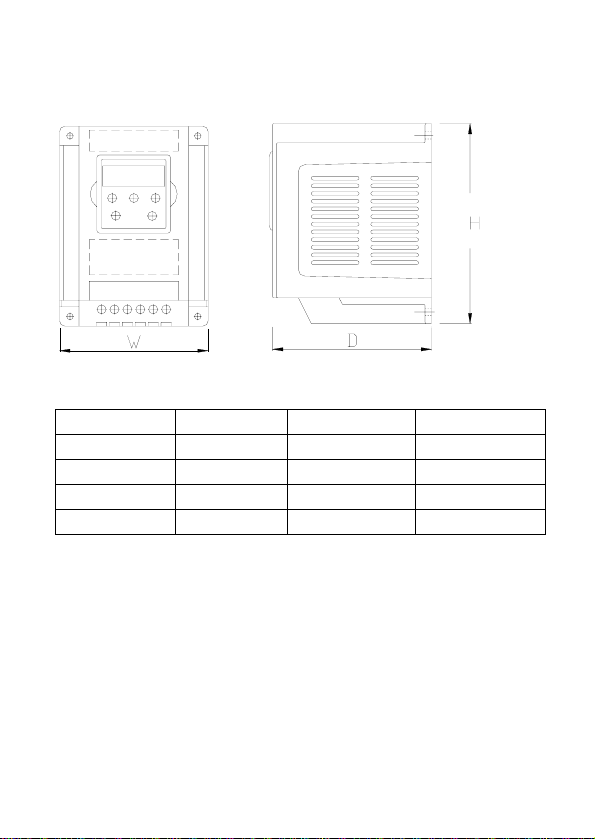
4.1 Exterior Size
400V 1~2HP 3-5HP 7~10HP
200V 1~2HP 3-5HP 7~10HP
H 165mm 214 255
W 120mm 151 180
D 123mm 160 180

4.2 Operating environment
To ensure proper performance and long operation life, Follow the
recommendations below when choosing a location for installing B800
series frequency inverter, Make sure the B800 series frequency inverter
is protected from the following conditions
. Ambient temperature: hanging type, -10~45℃
Tank closed type, -10~40℃.
. Rain, Moisture (For enclosed wall-mounted type)
. Oil fog, salt spray
. Direct sunlight.(Avoid use outdoors)
.Corrosive gases or liquid
. Dust or metallic particles in the air.
. Physical shock, Vibration
. Magnetic noise (Example: welding machine,power devices etc)
.High humidity
. Radioactive materials
. Combustibles: thinners, solvents, etc.
.If few inverters are mounted into cabinet, Please kindly put them on
ventilated position where the good ventilation is available. Further to
mount the cooling fan inside the cabinet to make the ambient
environment under 45℃
. Sufficient mounting space within below stipulation

4.3 Notice
! Notice
•Please don’t hold the front cover when move, the right way is to
hold the heatsink of inverter so as to avoid falling down which
could injury person or damage inverter itself.
•Please mount inverter onto nonflammable materials like metal and
other else; please don’t mount it nearby nonflammable materials
to avoid fire.
•If few inverters are mounted into a controlling cabinet, cooling fan
must be mounted inside cabinet to ensure temperature of cabinet
inside is lower than 45℃to avoid overheat.
• Please cut offAC main power prior to remove keyboard.

5. Wire
5.1 Connection diagram
Note: 1. three phases 380V use R/L, S/N, T as AC main power input terminal, Single
phase 220V only uses R/L and S/N.
2. Braking resistors of single phase 220V/1hp-2hp & three phase 400V/1hp –
2hp are all inbuilt.
3. B800 Series inverter default as keyboard control (F-12=1), it will work after
AC main power input
5.2 Notes for operation
• Parameter F-01 can be set as Max.30000 rpm/Min. of motor rotary,
please use this parameter with care.
• If user wants to operate the RPM of motor higher (F-09/F-10
parameter) than the rated speed of motor, please confirm the
allowable range both motor and machinery.
• The cooling fan of inverter would automatically start to work once
the temperature reach 40℃, Also, it would stop working when its
temperature is under indoor.
• Please attention other relevant parameter settings once braking
resistor used.
• Please don’t check the signal on PCB when inverter is running.
• Parameters have already been set when ex-work, please don’t adjust
it casually.
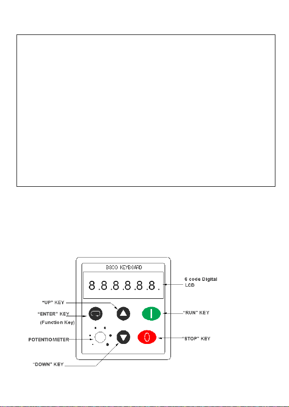
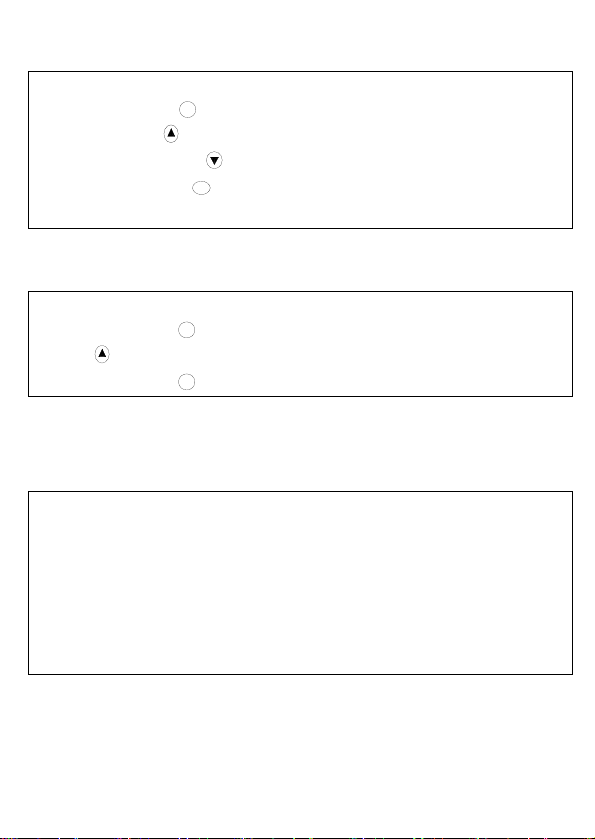
6.Keyboard Operation
6.1 LCD and operation Key (B800 Series without potentiometer)
(B800-1 Series with potentiometer)
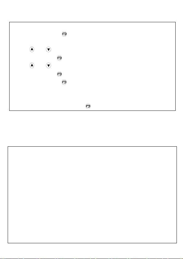
6.2 Utility for operation key
•When inverter ex-work, standard parameters are set as default.
•Press “Enter” key one second, then enter into check/modify
standard parameter group.
•Press or key to check the parameter group from F-01 to F-14
•Press “Enter” key again, which can read parameter value.
•Press or key, modify parameter value.
•Press “Enter” key again, Back to parameter group.
•If press “Enter” key more one second or standby more20 seconds,
Back to initial status prior to standard parameter group modification
•If want to enter into extended menu access(F-15-F-40),set F-14 to
“10”,and press “Enter” key .
7. Test operation
7.1 Master some relevant functions which may help you acquire more
ideal use effects
•Maximum and minimum output frequency F-01&F-02.
The maximum and minimum speed limitations are set according to
actual individual requirements.
•Accelerate and decelerate parameter F-03&F-04.
If linear acceleration time and linear deceleration time too short on
some occasions, which may cause inverter overcurrent and let inverter
trip, which cause motor stop working.
••Stop mode F-05.
When F-05=0, inverter would diminish motor’s speed according to
linear deceleration time.
If F-02≠0, when inverter start, motor would accelerate from mini
frequency we set (F-02), when inverter stops work, the motor linear
decelerate to ‘0’and then stop work.

If user want the motor stops work automatically (inertia stopping),
please sets F-05 to 1.
•V/F curve select F-06.
General loading F-06=0.
Such as fan, water pump etc. which are belonging to variable torque
loading, Pls set F-06=1, which will reduce the energy wastage when
motor run at low speed.
• Motor rated current, rated frequency and rated RPM(F-08, F-09, F-10).
Parameters should be set according to the nameplate on the motor.
When F-10 = 0, The Speed value appears with HZ.
If we set F-10 as motor rated RPM, which will help to improve slip
compensation function under different loading conditions
• Low speed voltage compensation (F-11).
Favorable to start motor smoothly, Maximum value of voltage
compensation up to 25%.
• Controlling methods select (F-12).
Terminal controlling method is for long distance control use.
Keyboard controlling method is for trial operation or handle manually.
• “Extended menu access” select(F-15~F-40)
“Extended menu access” is designed for inverter application experts,
engineers or technicians. General users don’t need to use it.
7.2 Keyboard operation mode( Default F-13=1 when ex-work)
•Put terminal 1, 2 open, the inverter appear to Stop
•Press “Run” Key 1,LCD appear to H0.0.
•Press “UP” Key ,frequency output increase.
•Press “DOWN” Key ,frequency output descends.
•Press “STOP” Key 0, Inverter stop frequency output, LCD appears to
stop.
7.3 Forward/Reverse operation on Keyboard
•Set F-12=2.
•Press “RUN” Key 1, LCD appears to H0.0.
•Press key,Speed increase.
•Press “RUN” Key 1again,Change motor rotary direction.
7.4 Terminal controlling operation mode
•Parameter F-12=0.
• Connect the start/stop switcher between terminal 1 and 2.
• Connect one potentiometer (1KΩ~10KΩ) among terminal 5, 6 and 7
• When “Start/Off” switcher ON, Turn potentiometer to change output
frequency (HZ) making the motor rotary
• When “Start/Off” switcher OFF or turn potentiometer to “0”, Inverter
stop work

7.5 Parameters resume default (Parameters reset)
•When inverter stop and appear “Stop” on LCD, simultaneity press ,
and “Enter” Key 01 second
•LCD appears P-SET, which means all parameters have resumed to
default (ex-work value).
•Press “Enter” Key 0again, LCD appears “Stop”.
•Parameter F-37 would restore to 10, but F-39 and F-40 not change.
7.6 The saving condition after parameter modification
•As F-38=0 (Default), all parameters could be modified, they would be
saved in EEPROM when AC main power is cut off.
•As F-38=1, all parameters could also be modified, but they would not
be saved in EEPROM when AC main power is cut off.
•As F-38=2, all parameters couldn’t be modified, read only.
Notice
To prevent other persons modify parameters causally, please select any
number between 0 and 9999 for parameters F-37 (enter into “Extended
menu access” password).
•Under status of “Extended menu access” (expect F-00),LCD would
return to initial status if without any operation within 20 seconds.
•when set as F-00, LCD would return to initial status if without any
operation over 60 seconds.
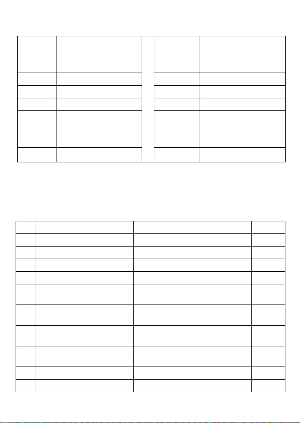
8. The symbol explanation on LCD
Symbol
on
LCD Explanation Symbol
on LCD Explanation
H50.0 Frequency output 50HZ A4.5 Output current 4.5A
1480 RPM 1480r/ min Stop Inverter stop work
F01 Parameter F-01 L Parameter lock (F-38)
E Parameter Error,
Modified only when
inverter stop
Radix
point
twinkling Inverter over-load
Stndby Standby
9. Parameter and datasheet
9.1 Parameter list
STANDARD PARAMETER
Par Description Range Default
F-01 Maximum speed F-02 to 5*F-09 (max 545Hz) 50Hz
F-02 Minimum speed 0 to F-01 (max 545Hz) 0Hz
F-03 Linear Accel time(s) 0.1 to 3,000s 5s
F-04 Linear Decel time(s) 0.1 to 3,000s 5s
F-05 Stop mode select 0, 2: linear stop (ramp stop)
1: inertia stop (coast to stop) 0
F-06 V/F characteristic 0: Constant torque, INDUSTRIAL
1: Pump/fan, HVAC 0
F-07 Rapid linear Decel time (s)
when power cut 0.0 to 25s. (Disabled when 0.0s) 0.0s
F-08 Motor rated current 25% -100% of drive current rating Drive
rating
F-09 Motor rated frequency 25Hz to 545Hz 50 Hz
F-10 Motor rated speed 0, F-09*12 to F-09*60 0

F-11 Voltage boost 0 to 25% of max output voltage 8%
F-12 Terminal or Keypad control 0: Terminal control
1: Keypad control –fwd only
2: Keypad control. fwd and rev 1
F-13 Trip log Last four trips stored Read only
F-14 Extended menu access Code 0 to 9999 0
EXTENDED PARAMETER SET
F-15 Motor rated voltage 220V product:80V to 250V
400V products:150V to 500V 0
F-16 Analog input format (V/mA) Voltage: 0-10V, 10-0V,-10V-10V
Current:4-20mA,0-20mA,20-4mA 0-10V
F-17
Effective power stage
switching frequency
(Carrier wave frequency
selection)
4,8, 16kHz 16 kHz
F-18 Relay output function
0: Drive enabled
1: Drive healthy
2: At set speed
3: Speed >zero
4: Motor at max speed (F-01)
1(Drive
healthy)
F-19 Multi-function contact input
selection 0 to 11 0
F-20 Preset /Jog speed 1 -F-01 (reverse) to F-01 50Hz
F-21 Preset /Jog speed 2 -F-01 (reverse) to F-01 0Hz
F-22 Preset /Jog speed 3 -F-01 (reverse) to F-01 0Hz
F-23 Preset /Jog speed 4 -F-01 (reverse) to F-01 0Hz
F-24 Slip compensation 20% to 250% 100%
F-25 Analog output function
(A) 0:Motor Speed
1:Motor current
(D) 2:Drive enabled
3: Set speed
0
F-26 V/F characteristic adjustment
factor 20% to 250% 100%

F-27
Skip freq /
speed 0 to F-01 (max) 0Hz
F-28 Skip freq /
speed band 0 to100% of rated speed/freq. F-09 0Hz
F-29 V/F characteristic
adjustment frequency 0 to base frequency (F-09)
(Function disabled when set to 0) 0Hz
F-30 Drive start mode
Edge-r: Close Digital input 1 after
power up to start drive
Auto-0: drive runs whenever digital
input 1 closed.
Auto-1-4: as Auto-0, except 1..4
Attempts to restart after a trip.
Auto-0
F-31 DC injection voltage 0.1 to 20% of max voltage 10%
F-32 DC injection braking time 0 to 250s 0s
F-33 DC injection on enable 0: Inactive 1: Enabled 0
F-34 External Brake Resistor
0: No brake resistor fitted
1: Optidrive braking resistor
2: Customer specified resistor
1
F-35 Speed reference scaling factor
(analog or digital) F09 * (1% to 500%) 100%
F-36 Drive address(s-comms) 0 to 63 1
F-37 Access code definition 0 to 9999 10
F-38 Parameter access lock
0: Parameters can be changed,
auto-saved on power down
1: Parameter changes not saved
on power down
2: Read-only. No changes allowed.
0
F-39 Hours run meter 0 to 99999 hours Read
only
F-40 Drive identifier Drive rating /Software version Read
only

Parameter explanation to only-read window
Parameter
No. Explanation to surveillance content
Range
of
setting
Factory
setting
value
F-00
1:Originalanaloginput %
2:Original analog input (F-35) Hz
3:Settingfrequency Hz
4: Output frequency Hz
5:Slipfrequency Hz
6:Stator frequency Hz
7:Motorvoltage VAC
8:DCbusvoltage VDC
9: Inside thermistor (NTC) 0~255
0~9 1

Multi-function contact input (Digital input)
F-19 Multi-function
Contact 2 Multi-function
Contact 3 Multi-function
Contact 4
0
Open: Stop (disable)
Closed: Run (enable) Open: Analog speed
reference
Closed: Preset /Jog Speed
1
Open: Voltage analog
input
Closed: Current analog
input
1 Open: Stop (disable)
Closed: Run (enable)
Open: Analog speed
reference
Closed: Preset /Jog Speed
1or 2, selected by Digital
input 4
Open: Preset /
Jog Speed 1
Closed: Preset /
Jog Speed 2
2 Open: Stop (disable)
Closed: Run (enable)
Digital Input 3 Open +Digital Input 4 Open =
Preset /Jog Speed 1
Digital Input 3 Closed +Digital Input 4 Open =
Preset /Jog Speed 2
Digital Input 3 Open +Digital Input 4 Closed =
Preset /Jog Speed 3
Digital Input 3 Closed +Digital Input 4 Closed =
Preset /Jog Speed 4
3
Open: Stop (disable)
Closed: Run (enable) External trip input:
Open: TRIP;
Closed: no trip.
Open: Analog speed
reference
Closed: Preset /
Jog Speed 1
4
Open: Stop (disable)
Closed: Run (enable) Open: Run forward
Closed: Run reverse
Open: Analog speed
reference
Closed: Preset /
Jog Speed 1
5
Open: Fwd Stop
(disable)
Closed: Fwd Run
(enable)
Open: Reverse Stop
(disable)
Closed: Reverse Run
(enable)
Open: Analog speed
reference
Closed: Preset /
Jog Speed 1
6 Open: Stop (disable)
Closed: Run (enable)
Open: Run forward
Closed: Run reverse
External trip input:
Open: TRIP;
Closed: no trip.

7
Open: Fwd Stop
(disable)
Closed: Fwd Run
(enable)
Open: Reverse Stop
(disable)
Closed: Reverse Run
(enable)
External trip input:
Open: TRIP;
Closed: no trip.
8
Open: Stop (disable)
Closed: Run (enable) Open: Run forward
Closed: Run reverse
Open: Preset /
Jog Speed 1
Closed: Preset /
Jog Speed 2
9
Open: Fwd Stop
(disable)
Closed: Fwd Run
(enable)
Open: Reverse Stop
(disable)
Closed: Reverse Run
(enable)
Open: Preset /
Jog Speed 1
Closed: Preset /
Jog Speed 2
10
Normally Open
(N.O.)
Momentary close to
run fwd
Normally Closed (N.C.)
Momentary open to Stop
(disable)
Open: Analog speed
reference
Closed: Preset /
Jog Speed 1
11
Normally Open
(N.O.)
Momentary close to
run fwd
Normally Closed (N.C.)
Momentary open to Stop
(disable)
Normally Open (N.O.)
Momentary close to run
reverse
• Forward means motor rotary along clockwise direction
• Multi-functions contact input selection “F-19” set to “0”
When multi-function contact 4 “OFF”,Analog input is voltage signal,
When multi-function contact 4 “ON”,Analog input is current signal,
The type of analog input signal can be set through parameter F-16.
If parameter F-19 set to 5 or 7 or 9, when use machine braking, multi-function contact
2 or 3 “OFF” or multi-function contact 3 or 4 “OFF”, Inverter not output, the motor
would be inertia stop.
•As F-19=6 or 7 and choose keyboard operating mode (F-12=1 or 2),External trip
function will be activated, when function contact is OFF, the inverter appear fault.

•Under keyboard operating mode, as F-12=1 or 2 and F-19=6, the rotary direction is
controlled by multi-functions contact 3, which means the inverter can be started in
reverse direction under the mode of keyboard operation.
•Under keyboard operating mode, as F-12=1 or 2 and F-19=7, multi-function contact 2
and 3 “ON” simultaneously which would activate the function of “Rapid linear
deceleration function (F-07).
9.2 Parameter explanation
Standard parameter group
•F-01 max output frequency
Maximum frequency limitation
(Speed, refer to F-10)
•F-02 min output frequency
Minimum frequency limitation
(Speed, refer to F-10)
•F-03 linearAccel time(S).
The required time accelerate from 0 to max speed.
•F-04 linear Decel time(S).
The required time decelerate from max speed to 0
•F-05 stop mode select
0: Decelerate and stop according to parameter F-04;
2: Decelerate and stop according to parameter F-07;
1: Input “Stop” instruction, motor coast to stop (inertially).
This manual suits for next models
6
Table of contents
Other Bedford DC Drive manuals

Popular DC Drive manuals by other brands


GFA
GFA ELEKTROMAT SI 260.9-80,00 installation instructions

Efka
Efka DC 1550 instruction manual

FALK
FALK Ultramite UB Installation & maintenance instructions

LS
LS Starvert SV-iC5 Easy start guide

PS Automation
PS Automation PSF-Q Short operating instructions

YASKAWA
YASKAWA JVOP-181 Driver installation guide


