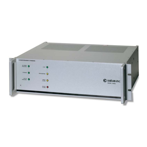
Bedrock SM50 User manual

Bedrock SM50
Operating manual
© 2015 Embedded Acoustics BV Document version 1.4
IEC 60268-16 rev. 4
IEC 61672 Class 2 / ANSI S1.4 Type 2

2 Bedrock SM50 operating manual © Embedded Acoustics BV, 2015
Contact information and support
The Bedrock SM50 is designed and manufactured by Embedded Acoustics BV in the
Netherlands, by the very team that originally developed the Speech Transmission Index.
You can contact the manufacturer at the following address:
Embedded Acoustics BV
Ampèreweg 18
2627 BG DELFT
The Netherlands
www.embeddedacoustics.com
www.bedrock-audio.com
Phone: +31 88 8770700
Fax: +31 88 8770799
Email: [email protected]
Updates of the system’s firmware and documentation are released online :
www.bedrock-audio.com
NOTE: Screenshots and product pictures shown in this manual correspond to the SM50
hardware platform 1.0 running firmware version 1.4. Once you update the firmware, the
screenshots may not fully correspond to what is being displayed on your device’s screen.
© Embedded Acoustics BV, 2013-2015. All rights reserved.
Embedded Acoustics and Bedrock are registered trademarks.
Document version 1.4, release date May 2015. Applies to model(s): SM50.

2 Bedrock SM50 operating manual © Embedded Acoustics BV, 2015
3
Contents
Contact information and support 2
1. Introduction 4
2.General use and safety precautions 5
Safety precautions when charging 5
Safety precautions related to connectors 6
3. Getting started 7
4. Using the SM50 8
Quick STIPA 8
STIPA pro 12
SPL meter 16
Real-Time Analyzer (RTA) 19
Settings 21
Calibration 24
Status 26
Accessing saved measurements from a PC 26
5. Power and charging 28
Charging instructions 28
Power saving recommendations 29
Use of power banks and external battery packs 29
6. Cleaning, maintenance and calibration 30
Battery disposal 30
7. Product warranty 31
8. Firmware updates 33
9. Buttons, icons and symbols 34
10. Technical specifications 36
11. Troubleshooting 37
EC declaration of conformity 38

4 Bedrock SM50 operating manual © Embedded Acoustics BV, 2015
1. Introduction
Congratulations on purchasing the Bedrock SM50 STIPAmeter, the most advanced instru-
ment for measuring the Speech Transmission Index ever built, designed and manufactured
by the inventors of STIPA. The SM50 is also a fully compliant Class 2 / Type 2 Sound
Pressure Level meter and a 1/1 and 1/3 octave Real-Time Analyzer. It offers a wide range
of measurement options, catering to a wide variety of different acoustic measuring needs.
Using the SM50 is quite easy, thanks to its touch-screen operation and intuitive menu
structure. Most users will get the hang of doing measurements with the SM50 without
spending much time with this manual. Nonetheless, we strongly recommend that you do
read through this manual before starting to use your SM50, in order to get acquainted with
the various features of the device and the procedures for charging and maintaining your
device. With a little care, you can expect years and years of reliable and trouble-free opera-
tion from the SM50.
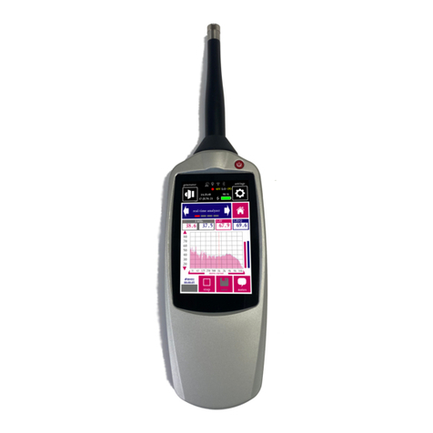
Class 2 / type 2
microphone
Power button
Charge status LED
USB charge & data
port
Touch screen
Tripod mount
Hook for
carrying cord
Serial number

4 Bedrock SM50 operating manual © Embedded Acoustics BV, 2015
5
2.General use and safety precautions
The SM50 is a sophisticated electronic measuring instrument that should be used, main-
tained and stored with care:
• We recommend that you always use a lanyard to secure your device against
dropping, by suspending it around your neck or wrist. If you use a tripod
to mount the device during measurements, we recommend that you use a
sturdy model with a sufficiently wide base.
• Do not expose the device itself, the measuring microphone or charger to
rain, moisture or liquids of any kind. Take special care to prevent liquids to
permeate into the device through the connectors or along the display bezel.
• Do not operate at ambient temperatures over 35oC/95F
• Do not use close to flames or open fire.
• Do not use in environments where flammable or explosive materials are
used.
• Do not keep the device powered on while unattended for prolonged periods
of time.
• Use the charger only with the international adapter suitable for your region.
• Make sure that the device is switched off before transportation and storage.
• During transportation and storage, keep the device in a suitable casing or
container – preferably its original case. The device needs to be protected
from shocks and vibration (due to transportation or falling), excessive tem-
peratures, liquids and moisture, and any other external conditions that
could do damage to the device. Care should be taken that other objects can-
not come into direct contact with the display during transportation.
Safety precautions when charging
The SM50 is a battery-powered rechargeable device, with an internal low self-discharge
NiMH battery pack. This battery pack is designed for many years of operation, and there-
fore cannot be swapped out by the user. Recharging takes place through the mini USB
connector found on the left side of the device.
The SM50 is charged through the USB connector using high currents of
up to 1500 mA. While being charged, the device will heat up. DO NOT
CHARGE THE DEVICE WHILE IT IS INSIDE A CLOSED CON-
TAINER (BOX, BRIEFCASE, ETC.). Please make sure that the device
can shed excess heat while charging.

6 Bedrock SM50 operating manual © Embedded Acoustics BV, 2015
The supplied charger includes adapters for use worldwide, and operates on
a wide AC-voltage range of 100 – 240V. Do not use the charger if the casing
appears cracked or broken, or if it has been exposed to fluids or moisture.
Contact with components inside the charger while this is plugged in may
result in serious injury or death.
Safety precautions related to connectors
The SM50 features a USB connector and an XLR connector (to which the
microphone is attached). If you connect external devices to these connec-
tors, please ensure that these connections are protected against overvoltage
and power surges. The voltage supplied to the USB port should not exceed
5.5V. As the USB power circuitry is connected to the battery pack, excessive
voltage applied to the USB port may cause the battery pack to catch fire or
explode.
The XLR connector supplies 48V phantom power to the microphone. This
phantom voltage can be switched on and off through the hardware settings
menu. IMPORTANT: connecting equipment not designed for 48V phan-
tom power to the SM50 XLR connector (with phantom power switched on)
will permanently damage the connected device and/or the SM50. The man-
ufacturer explicitly denounces responsibility for any damages to third-party
hardware resulting from exposure to the SM50’s phantom power.

6 Bedrock SM50 operating manual © Embedded Acoustics BV, 2015
7
3. Getting started
You should receive your SM50 with sufficiently charged batteries to start the device and get
acquainted with its features. We do recommend that you fully charge the device using the
supplied charger before starting your first real measurement session.
First of all, connect the microphone to the instrument using the XLR connector at the top
of th device. Next, the device is powered on by pressing the red power button once.
Note: the power button is also used to power the device off. If you press the button while the
device is in operation, you will see a dialog window asking confirmation before powering
off. If the power button is kept pressed for 10 seconds in the “power on” state, the device
will be forced into the “off ” condition. This can be used to reset the device if it becomes
unresponsive (keep pressed to 10 seconds to switch off, then press again to restart).
The SM50 will boot into the main menu. You can launch its different modules from this
menu.
STIPA pro
: app that gives you access to all STI measurement details
Quick STIPA
: simple app to quickly do STIPA measurements
SPL meter
: Sound Pressure Level meter app
Settings
: change the system’s hardware configuration
Calibration
: calibrate the SM50 and its microphone
Status
: general information on the measurement system
RTA
: Real-time analyzer
All modules will be explained in detail in the following sections of this manual. Apart from
these modules, the SM50 has two specific operating modes: charging via USB, and data
transfer via USB. These modes will also be explained further on in this manual.

8 Bedrock SM50 operating manual © Embedded Acoustics BV, 2015
4. Using the SM50
Quick STIPA
The Quick STIPA module is intended to do simple and straightforward STI measure-
ments using the STIPA test signal. A comprehensive explanation of the STI method is
beyond the scope of this device manual; there are several online and offline resources that
provide guidance and information on doing STI measurements, such as our own white
paper on this topic.
In this manual, we will briefly explain how to set up your equipment for measuring the
STI. The Quick STIPA module makes the process as simple as possible.
For any STI measurement, you need a source of the STIPA test signal as well as an STI
analyzer. In your case, the analyzer is your SM50. You can choose whatever type of STIPA
signal source that suits your application best (TalkBox, media player or otherwise).
The Embedded Acoustics reference STIPA test signal is included with the SM50 (on a USB
flash drive) and can also be downloaded from the Bedrock website, free of charge. This is
a fully IEC-60268-16 rev.4 compliant test signal, compatible with all STIPA meters that
conform with the standard.
Measurement screen of the Quick STIPA module, in digit mode (left) and bar mode (right)
In order to carry out an STI measurement, complete the following steps:
• Power on your SM50 and go to Quick STIPA
• Now start playback of the STIPA test signal through the channel or system
which you intend to test.

8 Bedrock SM50 operating manual © Embedded Acoustics BV, 2015
9
• Note that the STI that you will now measure, will characterize all parts of
your transmission path, from playback device up to the microphone of your
SM50.
• Tap “Start” on the SM50
• Wait for 18 seconds while the measurement takes place. Make sure that
signal playback is not interrupted, and that the acoustic environment is sta-
ble and free from impulsive sounds (such as door slams). Note: the STIPA
pro module uses a longer measurement time of 25s. A measuring time of 18s is
a reasonable minimum, within the range allowed by the standard, to arrive at
accurate results.
• You will see that the STI on your screen stabilizing towards its end value.
• Optionally, you can press “save” ( ) once the measurement is finished to
store the data, to be browsed or downloaded to PC later. A measurement
number is assigned to each saved measurement. This number is displayed
at the bottom right of the screen (preceded by a “#” character), above the
battery indicator.
The steps described above are essentially the entire procedure. If you are new to STIPA
measurements, please consult tutorials and standards to make informed decisions about the
STIPA signal playback level, measuring positions, number of repeated measurements, etc.
The Quick STIPA module also shows some additional measurement information:
• The A-weighted sound pressure level
• The qualification band (a letter between A and U) that is used in some
standards and defined in IEC 60268-16 rev. 4.
• A label (“bad”-”excellent”) the characterizes intelligibility based on the STI
The arrows in the blue bar on the top of the display van be used to navigate through the
different screens for each module. The Quick STIPA module has three screens: “STI”,
“settings”, and “browse measurements”.
The “settings” screen gives some options to control the appearance of your measurement
results:
• Choose between presentation of the STI in large digits or as a bar plot
• Choose whether or not you want to see the qualification bands displayed
The “browse measurements” screen allows you to review earlier (saved) measurements
without having to download your data to a PC first.
• Use the blue buttons at the bottom of the screen to scroll back and forth
through your saved measurements..
• Note that the measurement number displayed above the battery indicator
corresponds to the measurement currently shown on the screen.
“

10 Bedrock SM50 operating manual © Embedded Acoustics BV, 2015
Settings” screen and “browse measurements” screen. The latter screen is nearly identical to the
STI measurement screen, but with previous/back buttons instead of start/stop and save buttons.
Reviewing larger numbers of STIPA measurements by using the “browse measurements”
screen will be inefficient; we recommend downloading the data to a PC for this. Please refer
to the section “accessing saved measurements through a PC.”
Please take note of the following features of the Quick STIPA module:
• On the bottom left of the screen, a red “recording dot” ( ) is displayed
whenever a measurement is running. Below this red dot, the progress of the
current measurement is indicated by a progress bar ( ).
• The “save” button is only operational when new (unsaved) measurement
data is available from a finished measurement. If this is not the case, the
save icon is colored gray ( ).
• The qualification band (a letter between A and U) is just a different way to
represent the STI number; it is fully redundant. We currently recommend
working only with the STI value itself, unless the use of qualification bands
is explicitly required.
• The SM50 calculates a heuristic reliability metric for each STI measure-
ment. If the measurement is found to be unreliable (e.g. due to disturbance
by impulsive sounds), then a red cross is displayed across the STI value.
Crossed-out STI values are often seen at the beginning of measurements,
when the calculation has not ran long enough to compute a reliable STI. As
soon as the cross disappears, the STI value can be trusted to be within the
usual STI measurement error of 0.03.

10 Bedrock SM50 operating manual © Embedded Acoustics BV, 2015
11
A crossed-out STI value means that the measurement is not (yet) sufficiently reliable

12 Bedrock SM50 operating manual © Embedded Acoustics BV, 2015
STIPA pro
The STIPA pro module is also used to measure the Speech Transmission Index, but unlike
the quick STIPA module, it also comprises features that allow you to analyze and manipu-
late your measurement data in greater detail. It also uses a somewhat longer measurement
time (25s instead of 18s for Quick STIPA), for improved measurement accuracy.
“STI and spectrum” and “measurement details” screen in the STIPA pro module
The STIPA pro module has five screens:
STI and spectrum
: display measured STI, octave spectrum and dBA level
Measurement details:
display all measurement details including the MTF
Settings
: configure the STIPA pro module.
Additive noise:
enter and enable/disable a noise spectrum to add to data
Browse measurements:
review saved measurements
Measurements are usually started from the “STI and spectrum” or the “measurement de-
tails” screen. STI measurements are set up and started in the same way as when using the
Quick STIPA module (see above). However, in the STIPA pro module, more details about
the measurement are shown, and the user has more elaborate options to configure the
measurement. Measuremenst are started, stopped and saved in the same way as with the
Quick STIPA module (by using the buttons at the bottom of the screen).
The “STI and spectrum” screen shows not only the current STI value and the A-weighted
sound pressure level, but it also shows an octave band spectrum of the measured signal in
the 7 octave bands from 125 Hz to 8 kHz. The STI analysis is carried out in these octave
bands. The scale of the octave band spectrum plot can be modified by tapping on the trian-
gualar arrows to the left of the plot.

12 Bedrock SM50 operating manual © Embedded Acoustics BV, 2015
13
The “measurement details” screen shows all the diagnostic details of an individual STI
measurement:
• OCT: The octave center frequency (Hz)
• REL: The octave band levels relative to the STIPA signal spectrum (this is
effectively the frequency transfer function of the tested channel in octaves).
• MTI: Modulation Transfer Index. This quantifies the contribution to the
overall STI from each octave band.
• mr: the m-values (modulation transfer function in octave band OCT for
modulation frequency mf). These m-values are uncorrected, not adjusted
for masking effects and additive noise. Since the STIPA signal features two
modulation frequencies per octave band, there are also two m-values per
octave band. The modulation frequencies are also shown (mf)
• TI: the Transmission Index per octave band for each modulation frequency
These measurement details will enable more experienced operators to determine not only
the speech intelligibility of the tested channel, but also the causes of intelligibility reduction
induced by the channel.
Settings screen
The settings screen gives the user three options:
• Choose whether or not to display STI qualification bands ( -) as
standardized in IEC-60268-16. We recommend using these only if it is
explicitly required.
• Choose to enable or disable the level dependent model features: level-de-
pendent masking and the speech reception threshold. For standard measure-
ments, these features should be turned ON. Only when all-electric transmis-
sion chains are tested (without any acoustics involved) should these features
be turned off, since there is no acoustic level reference in those cases.
• Choose whether or not to (computationally) add noise to the measurement.

14 Bedrock SM50 operating manual © Embedded Acoustics BV, 2015
There are two ways to include the influence of background noise in your STI measure-
ment:
• Simply do your measurement in the actual noise environment. The STI
method is designed to incorporate the effects of any noise present during
the measurement representatively in the measured STI. This approach
works well if the noise field is stable and free from fluctuating and impul-
sive components.
• If you have the option to physically “turn the noise off,” then it is often
more accurate to add the noise computationally in a so-called post-hoc cal-
culation. The SM50 does this for you, if you enter the noise spectrum in
the “additive noise” screen and change the setting to “Noise included in
displayed STI.”
If you wish to add noise computationally, the screen “additive noise” should be used to en-
ter the noise spectrum. Note that the noise spectrum that you enter is only used if you also
select the corresponding option in the settings menu: entering the spectrum is not enough,
you also need to turn the additive noise feature on via the settings screen.
Additive noise screen
A few remarks about adding noise computationally:
• If you add noise computationally, all displayed STI values will be affected
until you turn the additive noise feature off again. The main display field
will now show the STI including the effect of noise.
• At the same time, the noise-free STI (as directly measured) is shown beside
the indication “no noise:”
• Whenever additive noise feature is enabled, the label “N!” is shown next to
the main STI display field. This is just a reminder that the displayed value
includes the effects of (computationally added) noise.

14 Bedrock SM50 operating manual © Embedded Acoustics BV, 2015
15
• To enter a specific noise spectrum, simply tap each octave band field on the
“additive noise” screen and enter the corresponding octave band level
• Alternatively, you can do a measurement (without STIPA signal playing!) of
the current background noise. Although the STI value will be meaningless,
the noise spectrum will be measured accurately. Save the measurment, and
then press “take from last measurement” ( ) on the “additive noise”
screen. The spectrum now represents the noise spectrum just measured.
• If you enter an A-weighted value after pressing the “A-wgt” field, all bands
will be increased with an equal amount until the A-weighted level is
matched. This is a quick way to lower or increase the overall level, and
also to generate a pink noise spectrum of a given A-weighted level (as the
default spectrum shown is pink).
• The buttons “-1 dB” and “+1 dB” adjust the levels in all bands by 1 dB.
You can browse through all measurements saved earlier in the “browse measurements”
screen. The following tips and pointers may be useful to remember when browsing STI
measurements with Quick STIPA and STIPA Pro:
• Measurements saved in Quick STIPA can be browsed in STIPA pro, and
vice versa. The measurement numbering range is shared between these
modules. This means that you can use STIPA pro to investigate measure-
ments done with Quick STIPA in more detail using the browsing screen in
STIPA pro.
• The settings you choose in STIPA pro (additive noise, level dependent
masking) affect the current measurement, but also affect which data is
shown in the measurement browser. This means that you can always enter
a noise spectrum and see how this affects measurements you did earlier
on. Similarly, you can go back later on and see what affect level dependent
masking has for a certain measurement.
• All data for each measurement is always saved - including any data not
actually shown during the measurement itself, including the time and date.
• Measurements can also be retrieved over USB; please refer to the section
“accessing saved measurements on a PC” for further instructions. For larger
numbers of measurements, processing of these saved data files (e.g. through
worksheet software) may be more efficient than inspection through the
measurement browser.
• If you wish to reset the measurement number (restarting at number 1), you
need to connect the device to a PC. Remove all measurement files (.CSV)
from the directory STIPA, as well as the file _INDEX.DAT.

16 Bedrock SM50 operating manual © Embedded Acoustics BV, 2015
SPL meter
The SM50 is also Sound Pressure Level meter (also known as SPL meter or SLM) that
complies with IEC 61672 Class 2 and ANSI S1.4 Type 2. In fact, the SM50 electronics far
exceed the requirements for a Class 2/Type 2 device.
The layout and buttons of the SPL meter module are similar to the STIPA modules, featur-
ing three screens: SPL measurements, settings and browse measurements.
SPL measurements screen, during measurement (left) and with settings keyboard showing
(right)
The following sound pressure level measurement settings are supported:
• Time weighting: Fast (F) and Slow (S)
• Frequency weighting: Z (linear, unweighted), A-weighted, C-weighted
• Max hold (holds and displays the maximum level during the measurement
interval; used with either Fast or Slow time weighting)
• Equivalent continuous (EQ): computes the time-integrated level over the
measurement interval; the level shown corresponds to the level of a contin-
uous signal containing the same amount of energy as the measured signal.
• Peak values (PK): the highest instantaneous value within a measurement
interval.
Note that MAX and PK are not the same; MAX represents the highest measurement over
a short time averaging period (either FAST or SLOW), and PK represents the highest
instantaneous value in the signal (even if this is a peak of very short duration). The SM50
allows PK measurements in combination with any frequency weighting, but only LCPK
is commonly used.

16 Bedrock SM50 operating manual © Embedded Acoustics BV, 2015
17
Once a measurement has started, each combination of the above settings is measured si-
multaneously. However, not all of these combinations are displayed: only two level meas-
urements are displayed at the same time. Each of these two levels is shown in its own bar
graph and its own digit field. The red graph corresponds to the red field, the blue bar graph
to the blue field. You are free to select which level to display in each of the two fields. Tap
the “set” button in the level field to choose time weighting, frequency weighting, max hold
and time integration settings for the corresponding field.
The SM50 will warn you if the signal level is outside the linear range of the microphone.
This occurs if the signal level is too low in comparison to the noise floor of the microphone
(underrange ) or if it approaches the maximum acoustic level that the microphone can
handle (overload ). Both types of range warnings are shown as a warning label next to the
corresponding measurement value.
Range warnings are shown in both level fields if the signal level is either too low or too high
(such as in this example).
The limiting factor for the overall dynamic range of the measuring system is
usually the microphone. If the standard microphone is replaced by a micro-
phone of a different type, the displayed overload and underrange warnings
may not be reliable. Please check the Bedrock audio online support pages
to find out for which microphone types (besides the standard microphone)
range warnings are supported. If you replace the microphone, it may be nec-
essary to patch the system firmware with a specific update package.
For MAX, EQ and PK measurements, the range warnings will be displayed from the mo-
ment the underrange or overload condition occurs until the measurement is restarted. For
FAST and SLOW measurements, the range warning will disappear once the overload/
underrange condition has passed.

18 Bedrock SM50 operating manual © Embedded Acoustics BV, 2015
The settings screen in the SPL module allows you to set the measurement time. Once you
press start, the measurement will run for as many seconds as you choose here. You may also
choose to let measurements run continuously; you then determine the measurement time
manually, by choosing the moment you press “stop.”
The SPL meter module also features are measurement browser, that lets you review previ-
ously saved sound pressure level measurements. Note that the measurement browser will
not display FAST or SLOW values, only MAX, EQ and PK. The reason for this is that
FAST and SLOW values are fluctuating measures; these are not single values character-
izing the measuring interval corresponding to any measurement number, and therefore
cannot be displayed except in real-time, during the measurement itself.
A few things to note about SPL measurements and the SPL meter module:
• By definition, “max hold”, “EQ” and “PK” are mutually exclusive settings.
• The elapsed measurement time is shown above the progress bar. If the
measurement interval is set to “continuous,” the measurement will run un-
til it is manually stopped. Note that, in practice, the maximum measuring
time is limited by:
• The battery. When measuring continuously, the battery is drained
relatively quickly (within 3-4). For longer measurements, we rec-
ommend using the charger or an external power bank.
• Internal data storage, especially if you are recording all measure-
ment audio (per the option in the “Settings” module). When re-
cording audio, the internal storage fills up in about 5 hours.
• When you press “save,” data from the current measurement is stored. Re-
sults based on all time and frequency weightings are saved; not just the
results that are currently displayed. However, as remarked above, since the
instantaneous levels fluctuate throughout the measurement, these cannot
be saved as a single number representing the entire measurement interval.
So for each saved measurement, just the maximum level (max hold) and
equivalent continuous level (EQ) and Peak level (PK) are saved.
• As a logical consequence, the measurement browser can only display Max
Hold, EQ and PK results from earlier measurements. If you set a display
field to show instantaneous values, the measurement browser will leave this
display field blank.
• You can use the measurement browser to go back to earlier measurements,
and see what the level is with different time- and frequency weightings
applied.
• The measurement number series used for SPL measurement is separate
from the STIPA measurement numbers. An SPL measurement and a STI-
PA measurement can have the same number, without data being overwrit-
ten.

18 Bedrock SM50 operating manual © Embedded Acoustics BV, 2015
19
Real-Time Analyzer (RTA)
The RTA module has two main modes of operation: as a 1/1 octave band analyzer (span-
ning the octave bands from 31 Hz to 16 kHz) and as a 1/3 octave band analyzer (25 Hz
through 20 kHz).
The operation is generally similar to the SPL module, but instead of just the overall signal
level, a frequency analysis (into 1/1 or 1/3 octave bands) is also shown.
RTA main measurement screen (1/3 octave band mode)
The RTA module has the ability to present two different spectral views at the same time,
differing in frequency weighting (A, C or Z) and time averaging and integration (FAST,
SLOW, MAX, or EQ). The main spectrum is presented in red bars, while a second (auxil-
iary) spectrum is shown in blue lines. The corresponding broadband levels are also shown,
to the right of the spectrum.
While the spectrum graph already gives a first impression of the spectral content of the
measured signal, you may wish to read the exact value in each band. This is done by placing
the cursor (dashed line) over the band of interest. The cursor can be moved left and right
by pressing on the left or right side of the frequency axis (or the area of the graph above
the axis). The values for the selected band are shown in the grey field on the top left of the
screen (main weighting shown in read, aux weighting in blue - same color as the spectrum
bars).
The “measuring time” screen can be used to set the duration of a measurement to a fixed
value. The measurement can also be set to run until stopped manually. The “settings”
screen allows you to switch between 1/1 and 1/3 octave band resolution, and to change the
weightings for the main and auxiliary spectrum views.

20 Bedrock SM50 operating manual © Embedded Acoustics BV, 2015
By pressing the “save” ( ) button in the main measurement screen, you store the current
measurement on the devices internal storage, using the measurement number indicated
above the battery indicator.
Some remarks about the RTA module:
• By definition, “max hold” and “EQ” are mutually exclusive settings.
• The elapsed measurement time is shown above the progress bar. If the
measurement interval is set to “continuous,” the measurement will run un-
til it is manually stopped. The progress bar itself is not used when measur-
ing continuously.
• Measurements saved as 1/1 octave cannot be retrieved as 1/3 or vice versa.
However, data recalled through the measurement browser are shown with
the frequency weightings selected at the time the measurement is recalled
- even if these are different from the settings that were in effect during the
measurement. This allows you to inspect the effect of frequency weightings
on all measurements saved previously
• Note that the spectrum and its corresponding broadband level are affected
by the same time- and frequency weightings. In other words, if the main
spectrum is A-weighted, then the level shown in the red field is also A-
weighed (and vice versa). If you wish to display a Z-weighted spectrum and
an A-weighted level at the same time, you need to display these in different
channels (main and aux).
• Note that the measurement number range for the RTA results is separate
from the SPL and STI measurement number range.
Other manuals for SM50
1
Table of contents
Other Bedrock Measuring Instrument manuals
Popular Measuring Instrument manuals by other brands
Paradyne
Paradyne FrameSaver SLV Series installation instructions

YSI
YSI 2900 series Operation and maintenance manual
TECALEMIT
TECALEMIT FMT 3 operating manual
DINTEK
DINTEK 6202-01001 manual
Apogee
Apogee MC-100 owner's manual

Electro Industries/GaugeTech
Electro Industries/GaugeTech Shark 100T quick start guide
