DINTEK 6202-01001 User manual


Handheld Optical Power Meter
MAIN INDEX
Safety Sign:
When using the optical power meter, always take bask safety precautions to reduce the harm for the
testers, and injury to persons. All the safety sign may not mark in this manual.
Warning:Prohibited misconduct and operation, to prevent any improper conduct and operation of
the damage.
Notice:notice the important information, notification, and references, these notice information
should be understand.
Safety sign on the instrument:
WEEE Sign:Users of electrical and electronic equipment from private households should have
the possibility of returning WEEE at least free of charge.
Safety Advice
1.When the tester use Disposable alkaline batteries, do not charge it. Ensure the correct polarity
installation, when replace the battery.
2.When the products are not in use, please remove the batteries and kept separate to avoid
instrument damage caused by battery leakage. If leakage occurred, Please do not touch.
3. To prevent electric shock, do not open the product case, only the authorized qualified
professionals can do the maintenance; Do not expose the testers to rain or wet conditions, to
avoid the risk of fire or electric shock
4. Instruments used LCD screen. Do not fall the instrument. If the LCD are seriously hit, it may cause fluid
leakage. And please do not touch.

Handheld Optical Power Meter
MAIN INDEX
Contents
Chapter 1. Standard Configuration……………..……………………………….1
Chapter 2. Overview…….……………………...……………...…………………..1
Chapter 3. Data Sheet……….……………………………………………..……...2
Chapter 4. Function………….………….……………………………..………......3
4.1 Front…………………………………………………..……………………………….3
4.2 Two Sides…………………………………………………………………..…………6
4.3 Top…………………………………………………………….……………..…………8
4.4 Backside……………………………………………………………………………….9
Chapter 5. Software..…………………………………...….…………………..….10
5.1 Install the device……………………..……………….………………………….….10
5.2 Install the application software……………………………………………………..14
5.3 Software function instruction……..…………………………………………….…..15
Chapter 6. Operation Instruction & Notes…………….……………………….18
6.1 Powering the Optical Power Meter………………………..………………………….18
6.2 Power on the optical Power Meter……………………...……………………….……19
6.3 Backlight setting……………………………………………………………………..….20
6.4 Output Power measurement……………………………………………………..……21
6.5 Data Communication…………………………………………………………….…….29
6.6 Wavelength Automatic Identification…………………………………………………29
6.7 Frequency detection……………………………..…………………………….………29
6.8 Power off………………………………………………………………………….……..30
Chapter 7. Troubleshooting …………………….….…..…......................…….30
Chapter 8. General Maintenance.………………………………………...…….31
Chapter9. Quality Warranty………………………….…………………….........31
1
1
2
3
3
6
8
9
10
10
14
15
18
18
19
20
21
29
29
29
30
30
31
31

Handheld Optical Power Meter
1
MAIN INDEX
Chapter 1: Standard configuration
No. name qty
1 Optical Power Meter 1
2 User Manual 1
3 USB cable 1
4 CD 1
5 1.5V AA battery 3
6 Power Supply Unit 1
7 Cotton Swabs 1
8 Carry Bag 1
Chapter 2: Overview
The DINTEK Handheld Optical Power Meter is a newly designed fiber optic
tester, aimed at the installation of fiber, engineering acceptance and
maintenance of fiber networks.
Compared to usual power meters, the DINTEK Power Meter has additional
functions, like automatic wavelength identification, auto wavelength switching,
intelligent backlight and data saving via USB port.
Combined with DINTEK Handheld Optical Light Source, it offers a quick and
accurate testing solution on both SM and MM fibers.
Wave ID—Auto wavelength identification & switching
Frequency ID ---Auto frequency identification
2 types of backlight modes, manual or outside light intensity, which
indicated by LED light red or blue color.
Intelligent backlight
1000 records storage or download via USB cable
USB communication port for saved testing records download
Reference power level can be set up and stored
User self-calibrating function
Auto-off function
Up to 200hrs battery life

Handheld Optical Power Meter
2
MAIN INDEX
Chapter 3: Data Sheet
Model
A
C
Calibration Wavelength
(
nm
)
850/1300/1310/1490/1550/1625
Detector type
InGaAs
Measurement Range
(
dBm
)
-70
~
+6
-50
~
+26
Uncertainty (dB)
±0.15
(
3.5%
)
linearity (dB)
±0.02
Display resolution(dB)
0.01
Frequency ID
(
Hz
)
270
,
330
,
1K
,
2K
Wave ID
(
nm
)
850,1300, 1310
,
1490
,
1550
,
1625
Date Storage Capacity
1000
Communication Port
USB
Standard Connector
FC /2.5mm universal
Optional Optical Connector
FC/SC/ST Interchangeable/2.5mm universal
Optional Optical Connector
LC/FC/SC/ST Interchangeable
Alkaline battery
3*AA
,
1.5V
Power Adapter(V)
8.4
Battery Operating time (h)
200 without backlight
Operation Temperature(℃)
-10
~
+60
Storage Temperature(℃)
-25
~
+70
Dimension(mm)
175*90*44.5
Weight(g)
231
Remark: Battery operating time is based on the condition of the power off the backlight. If power on the
backlight continuously, the operation time will be shorter.
Handheld Optical Power Meter
3
MAIN INDEX
Chapter 4: Function
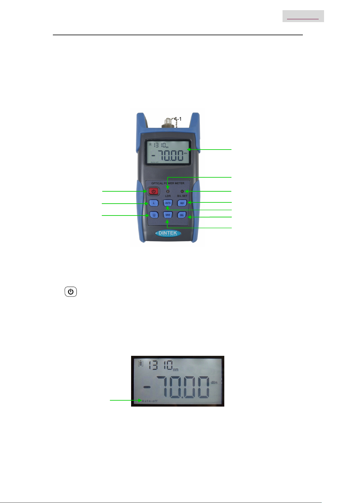
4.1 Front
4-1
(1) Power Key Turns the instrument ON/OFF.
Power Saving setting: Under power saving, the unit will automatically shut off after 15 minutes idle time,
whatever the condition of battery power supply or AC power supply. Once selecting this setting, the
“auto-off” will display on the left bottom of the screen. This power saving is the default setting, once
turned on, the power meter will enter into this mode. Short press the power key to toggle on/off auto
power saving mode.
Power Saving
(8)
(7)
(6)
(5)
(4)
(3)
(2)
(1)
(9)
(10)

Handheld Optical Power Meter
4
MAIN INDEX
(2) Wavelength Selection/Wavelength identify
Short press this key to switch the wavelength and display it on the top left of the
LCD screen, 1310nm is the default wavelength.
Press the for 2 seconds to on/off the wavelength auto-identify mode.
On the upper right of the screen wil be displayed the letters “AU.
(2) backlight control (two modes of back light control, press this key to choose modes):
“LDR” the intelligent backlight control mode. Power meter will toggle off/on the backside within 15
seconds based on the outside light condition. “LDR” is the default backlight mode.
Back light control key mode. Press to on/off the back light
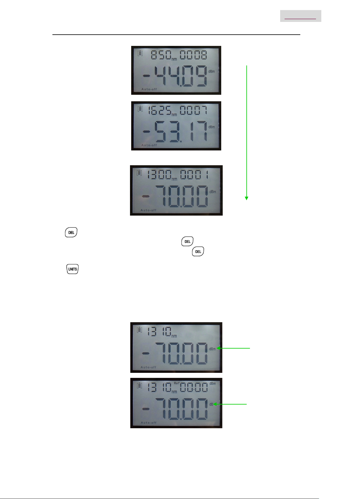
(3) Saving / Data-View key。
Using the Data-saving, the tester can save up to 1000 data records.
Press and the screen will display the data saving No.
Double press the to save the data.
Data view. To view data records, Long press to enter into the data view the interface.
Short press to view the data.
Calibrated wavelength
Wavelength auto-identify
Data Saving Record No.
Current saving data
(wavelength, output
power-dBm)
Handheld Optical Power Meter
5
MAIN INDEX
……
(5) Delete/Cancel Key.
1. Data Delete. When viewing specific data, press to delete the record.
2. Cancel the saving. When in the saving mode, press to cancel the current data saving.
(6) Unit switch key
Press the Unit key to switch between the absolute measurement(dBm) and relative
measurement(dB) and nW of the optical power.
mW、dBm conversion:10 log(mW)=(dBm)
mW、uW、nW conversion:1mW=103uW=106nW
dBm
dB
0001
0008

Handheld Optical Power Meter
6
MAIN INDEX
(7) REF setting:
To store the current power value as the reference value which will be displayed on the top right of the
LCD screen, at the same time the “Ref” also display on the right top. It will compare the current power
with the reference power and show the relative power value in dB.
The relationship between relative value(dB), absolute value(dBm), and Ref value: relative value=︱
absolute value︱-︱Ref︱
(8) “B/L SET” backlight indicator
Indicate backlight control mode. Green light indicates “LDR” intelligent backlight control mode, Red light
indicate that key-control mode.
(9) “LDR” Intelligent backlight controller
In the intelligent backlight control mode, the controller will automatically adjust the backlight with the
outside light, in order to save power.
(10) Screen
Display the data and the instrument working mode.
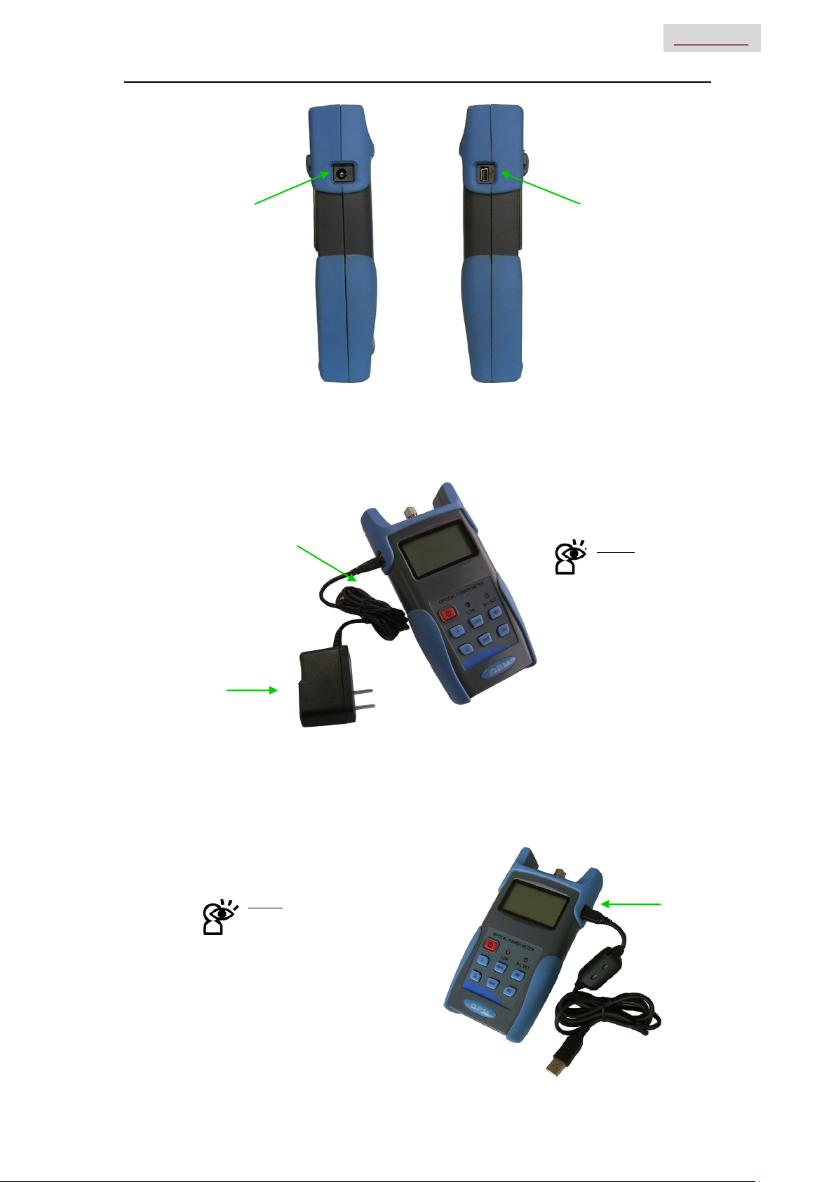
4.2 Two sides
Indicator
(Green)
Indicator
(red)
xW
Ref value setting
Relative value setting
Handheld Optical Power Meter
7
MAIN INDEX
4-2left side 4-3 right side
(1) Power Supply unit port
Used for connecting with the AC adaptor (pic. 4-4)
4-4
4-5
(2)
Mini USB Port
(1)
Power Supply
Unit
AC adaptor Notice:
Please use only the power
supply unit supplied with the
tester. Use of other kinds of
PSU may cause damage to
the instrument.
Notice:
USB Port. Use the USB cable
supplied to connect the Optical
Power Meter to The USB port
on PC pic. 4-5.

Handheld Optical Power Meter
8
MAIN INDEX
4.3 Top
4-6
(1)Dust Cap
In order to protect and avoid damage to the optical connector, when not in use make sure that you
place the dust cap over the connector.
(2)Optical Connector
The standard of this power meter connector a PC & Φ2.5mm universal connector. pic. 4-7 & 4-8.
Screw off the FC connector, and it will turn into a Φ2.5mm universal connector.
4-7 FC connector 4-8 Φ2.5mm universal connector
Notice: When changing the optical connector, take care of the connector and the end-face.
FC connector can connect with FC adaptor, Φ2.5mm universal connector can connect with FC, SC,
ST adaptor. Pic 4-9
4-9
Notice: Any dust on the connector will affect the accuracy of the measurement value. Please clean
the connector and the patch cord end-face before conducting the test.
Use an alcohol and the cotton swab to clean the connector. Dip the cotton swab with alcohol, insert the cotton
swab in the connector, slightly rotating the cotton swab, after that change a dry cotton swab and clean it again.
Pic. 4-10
FC Patch Cord SC Patch Cord ST Patch Cord
(2)
(1)

Handheld Optical Power Meter
9
MAIN INDEX
4-10
4.4 Backside
4-11
(1) Label
Content includes the function of, and the instrument information
(2) Bracket
Collapsible metal bracket, 0~90 degree can be adjusted.
(3) Battery Pack
This unit takes 3 x 1.5v AA batteries.
Notice: When inserting the batteries, take a note of their positive (+) and negative (-) connector
orientation, the negative battery connector should be against the spring.
(3)
(2)
(1)
Cotton Swab

Handheld Optical Power Meter
10
MAIN INDEX
Chapter 5 Software
5.1 Install the device
Run the software in the PC, find the “CH341SER-CH340T” as shown below
Double click that “exe” program. This will initiate program. See fig. 5-1
5-1
Click “INSTALL”. after you will see the following, Fig 5-2
5-2
Press “OK”, to exit this install interface.
However, the driver still has not installed yet, therefore continue the following operation:
Use USB cable connect with power meter and the PC, switch on the instrument, See Fig 5-3
5-3

Handheld Optical Power Meter
11
MAIN INDEX
Press “NEXT”, See Fig. 5-4
Fig. 5-4
After driver install, click FINISH to exit,See Fig. 5-5
Fig. 5-5
To check if the installation is complete and to avoid any communication problems, when the power meter
is connected with the P, open the “Device Manager” (right click “My computer” choose “property”, pop up the
property interface, choose “hardware option”, click “Device Manager”), find the “Port (COM 和LPT)” if your
interface is the same as the following pic in Fig.5-6, this means the install is a success. If the interface
does not show “USB-SERIAL CH340” as in Fig. 5-7, please re-install the devices.


Handheld Optical Power Meter
15
MAIN INDEX
Click “Finish”, Complete the installing (as per Fig. 5-13)
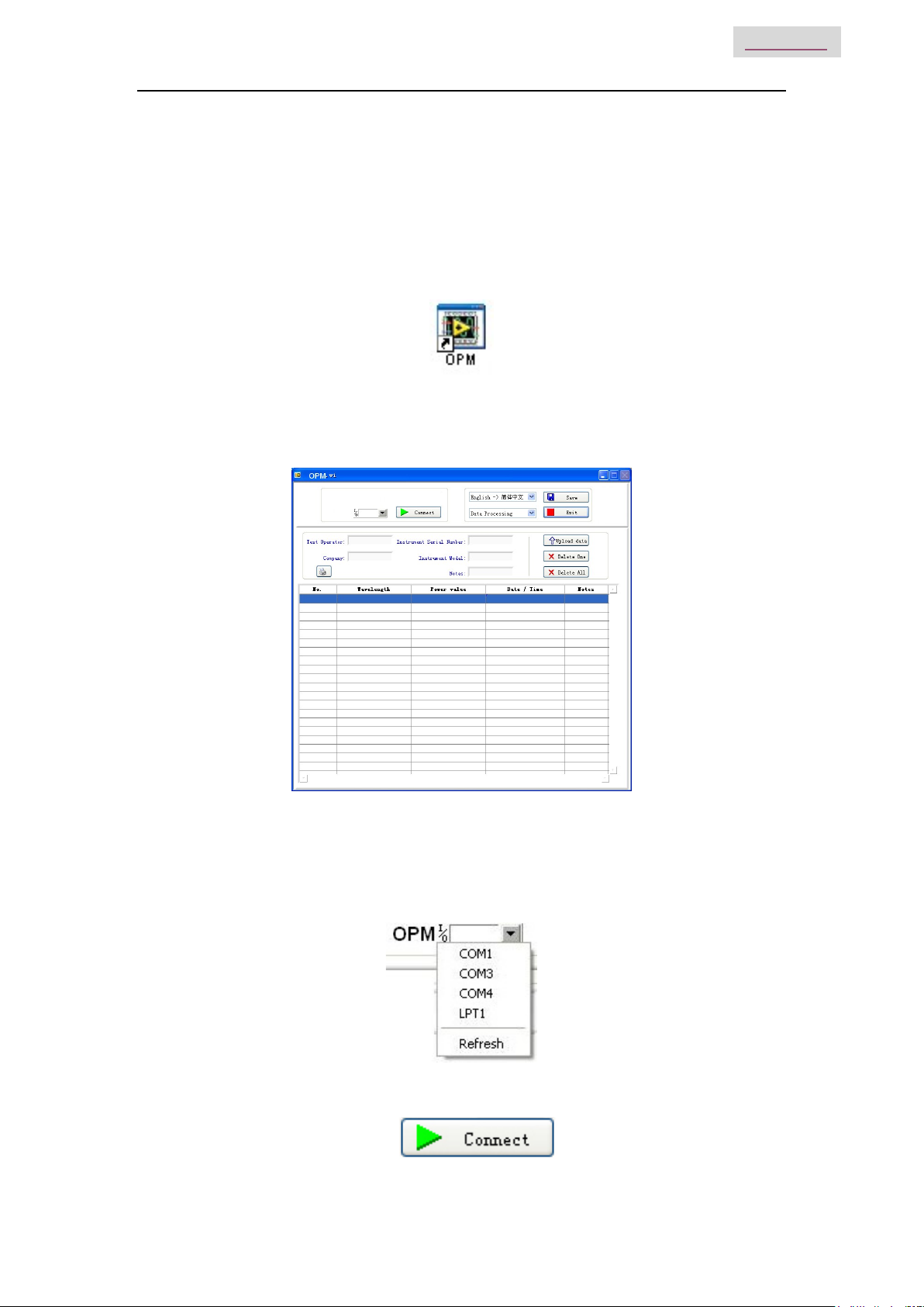
5.3 Software function instruction
This software has two functions: data processing, and the setting the instrument.
After finishing the software installation, find the short cuts icon for this software.
Double click this icon to open the software. You will see the software interface, (as per Fig. 5-14)
Data processing is the default interface once the software is opened.
5.3.1 Data Processing
Fig. 5-14
Data Processing interface include 4 parts.
(1) Manual
I. Port Option: Choose the right port, which the same port that the PC connects with
.
II. Connect icon, make the PC connect with the power meter, and communicate.
Handheld Optical Power Meter
16
MAIN INDEX
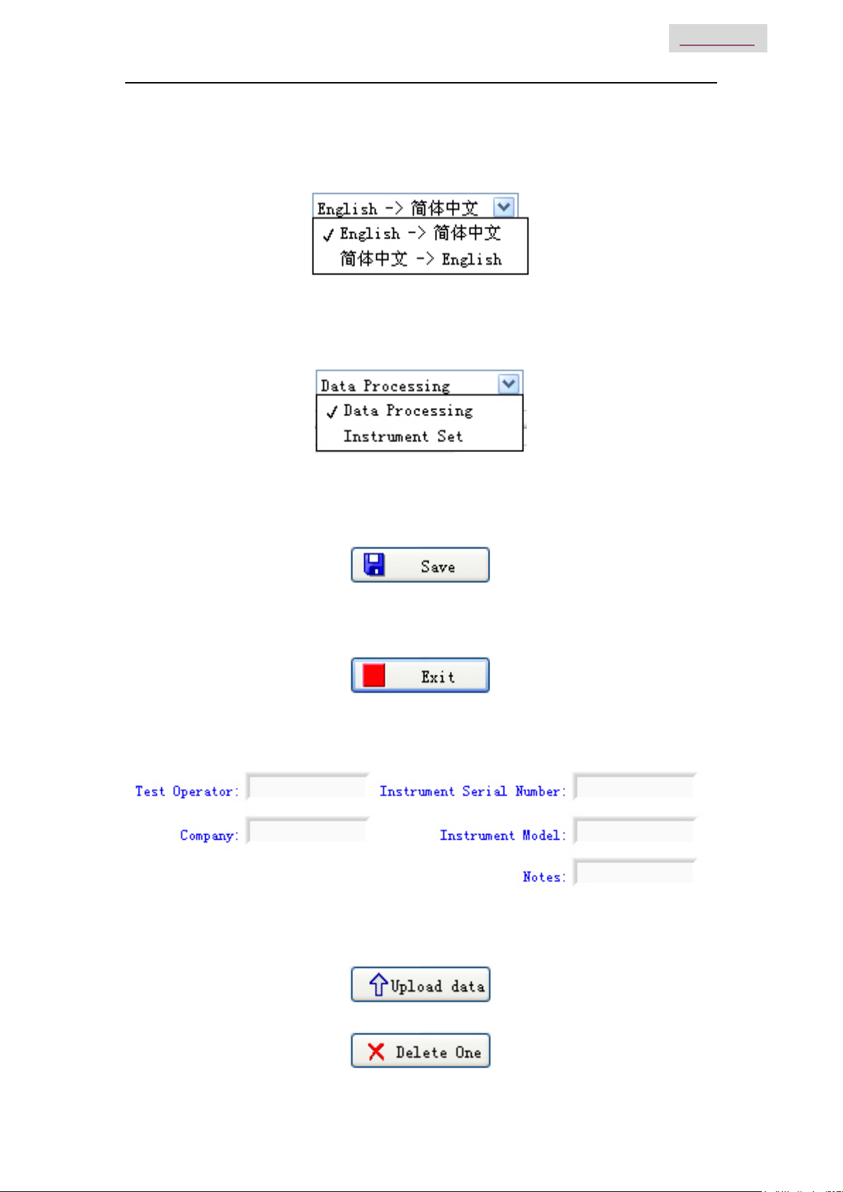
III. Language option, Drop-down the manual, Find the right language for the user prefer,
Chinese/ English.
IV. Function interface option: Two functions for option--data processing and the instrument
setting, drop-down the manual to choose.
V. Save button, save the current measurement data as the EXCEL file, convenience for
user to view and analysis the data on the PC.
VI. Exit button, disconnect the communication, close the software.
(2) Testing information form
Fill the information in the blank areas
(3) Printing button to print the measurement value.
(4) Data process button
I. Upload the data to the PC, display the data on PC, for the user view.
II. Delete the choose data.
Handheld Optical Power Meter
17
MAIN INDEX
III. Delete all the data that saved in the instrument.
(5) Data display area
To display the saved data of the instrument
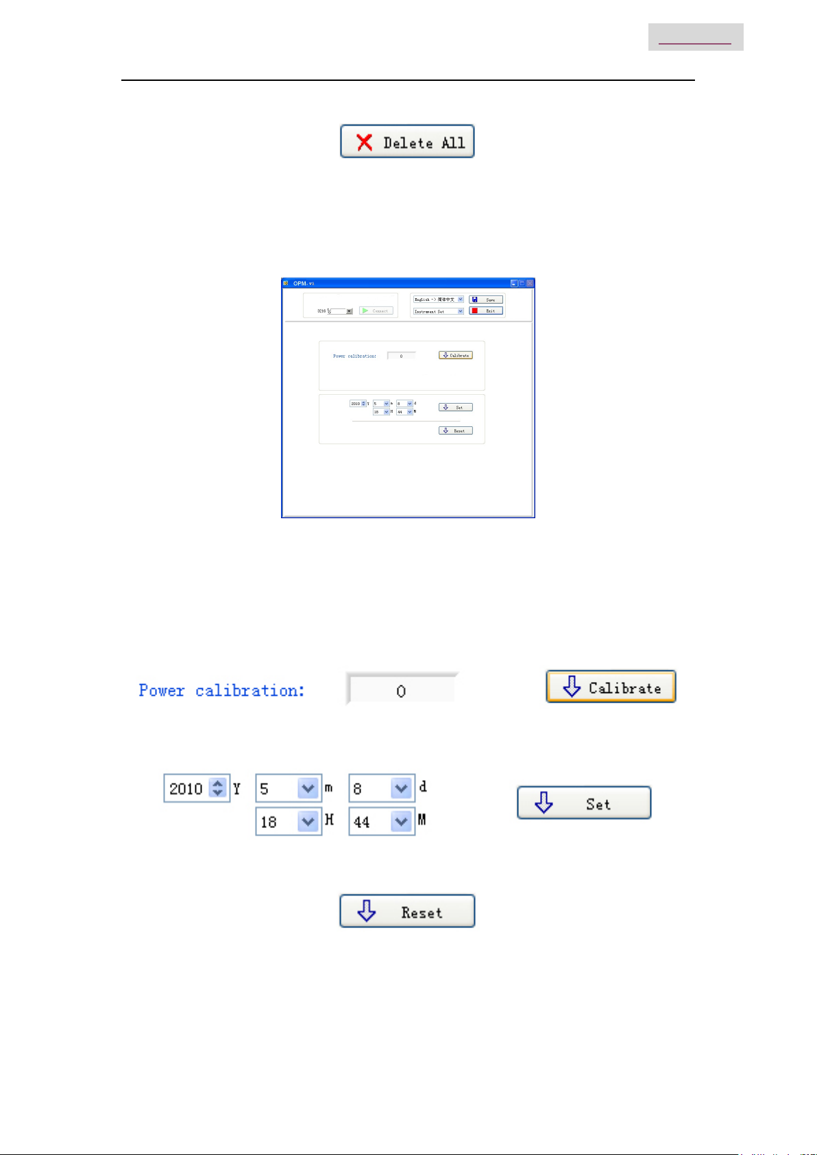
5.3.2 Power Meter setting
Fig. 5-15
Power Meter setting interface, pic. 5.3.2,which include 4 parts:
(1) Menu bar(Please refer description in data process interface)
(2) Calibration, the user can do self-calibration.
3Time Setting.
(3) Recover the factory default setting. Power meter calibration recover the factory default setting.
Table of contents


