BEEK BT-CT66 User manual

BT-CT66 Multi-function Wire Tracker
User Manual
• Thank you for purchasing the Wire Tracker. Please read the manual before using the Wire Tracker and use
properly.
• For using the Wire Tracker safely, please first read the (Safety Information) carefully in the manual.
• The manual should be kept well in case of reference.
• Keep the S/N label for after-sale service within warranty period. Product without S/N label will be charged for
repair service.
• If there is any question or problem while using the Wire Tracker, or damages occurred on the product, please
contact our technical Department.

BT-CT66 Multi-function Wire Tracker
User Manual
Content
1. Safety information...............................................................................................................1
2. Feature..................................................................................................................................3
3. Packing list............................................................................................................................3
4. Interface and Function Introduction...................................................................................4
5. The instruction of product application..............................................................................7
5.1 Cable tracer ................................................................................................................7
5.2 UTP detection .............................................................................................................9
5.2.1 Sequence and pair line continuity detection .................................................9
5.2.2 Network cable port continuity detection.......................................................9
5.2.3 Short circuit test .............................................................................................11
5.2.4 Continuity detection in the state of connected switches............................11
5.3 PD powered detected...............................................................................................12
5.4 Other features ..........................................................................................................12
6. Specifications......................................................................................................................13
1. Safety information
• The wire tracker is intended to use in compliance with the local rules of the electrical usage and avoid to apply
at the places which are inapplicable for the use of electrics such as hospital, gas station etc.
• To prevent the functional decline or failure, the product should not be sprinkled or damped.
• The exposed part of the wire tracer should not be touched by the dust and liquid.
• Don’t use the wire tracer where the temperature is high.
• Please don’t use this instrument to detect power lines (such as 220V power lines), otherwise it may damage the
instrument or involve personal safety.
• During transportation and use, it is highly recommended to avoid the violent collision and vibration of the
tester, lest damaging components and causing failure.
• The wire tracker should not be used in the environment with the flammable gas.
• Do not disassemble the instrument since no component inside can be repaired by the user. If the disassembly is
necessary indeed, please contact with the technician of our company.
• The instrument should not be used under the environment with strong electromagnetic interference

BT-CT66 Multi-function Wire Tracker
User Manual
2. Feature
• Secondary code digital mode, decisively rejects noise and false signals, locate cables quickly and easily.
• Cable tracer and UTP cable test in the same interface.
• Identify cable type:100M/1000M, straight/cross/other.
• UTP/STP/RJ45/RJ11 cable scan and continuity testing.
• Identify the status in the working telephone line: standby, ringing and off-hook
• Quickly detect the near-end, mid-end and far-end fault point of RJ45 cable plug
• UTP port support max 60V withstand voltage, the wire can be traced directly in connection with PoE switch.
• Shielded cable and shielding layer continuity test
• PD powered detection: detect whether the power output of the POE switch is normal, and detect the pins used
for power supply.
• Support silent mode
• Two bright LED lights for working in the dark
3. Packing list
1) Wire tracker emitter
2) Wire receiver
3) RJ45 cable
4) RJ11 cable
5) BNC alligator clip
6) User manual
BT-CT66 Multi-function Wire Tracker
User Manual
4. Interface and Function Introduction
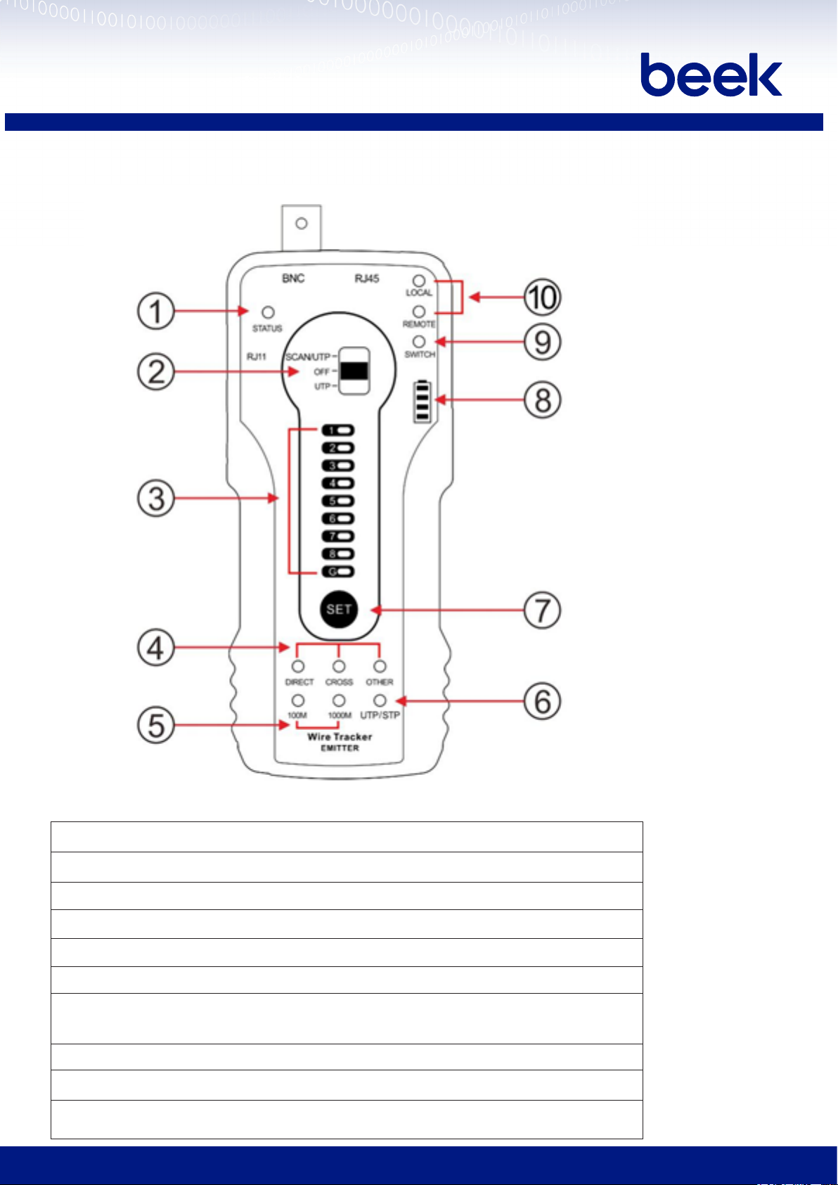
1) Emitter Interfaces and functions:
1 Telephone status indicator
2 Functions switch: SCAN/UTP, OFF, UTP cable test
3 UTP cable sequence/ continuity indicators, G is shielded cable
4 UTP cable type indicator: straight /cross /other
5 100M /1000M indicator
6 Cable tracer mode indicator: Green-normal mode, red-shielded mode
7 SET: Switch function shielded or unshielded in cable tracer mode and "local / remote
/ switch" in UTP cable test mode
8 Battery indicator
9 SWITCH continuity indicator
10 LOCAL/ Remote end continuity indicator
BT-CT66 Multi-function Wire Tracker
User Manual
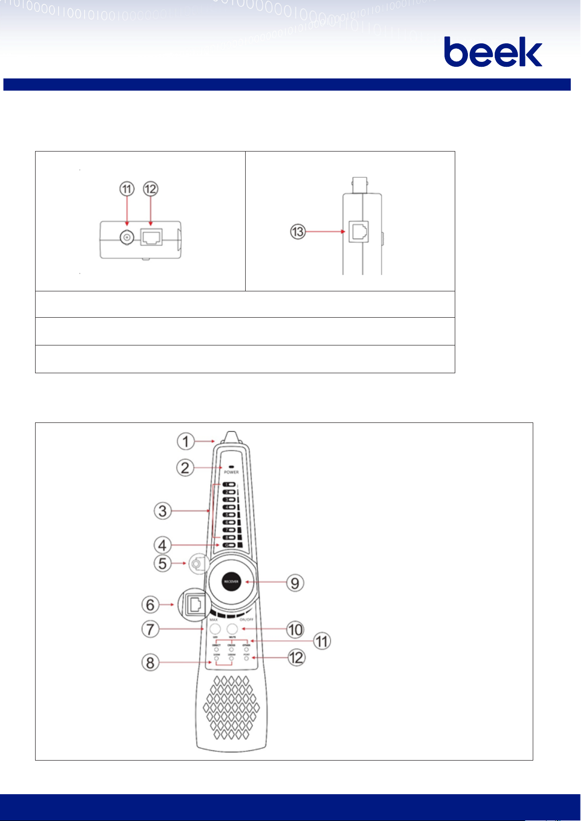
Top interface
Left interface
11 BNC interface
12 UTP/ Scan port
13 RJ11 port
Note: Please use telephone status detection in the OFF status. The indicator light off / on / flashing correspond to
telephone status standby / ringing / off-hook.
2) Cable tracer (Receiver) Interfaces and functions:

BT-CT66 Multi-function Wire Tracker
User Manual
1 LED light
2 Power Indicator
3 UTP cable sequence / signal strength indicator
4 Shielded layer continuity indicator
5 Earphone jack
6 UTP cable test port
7 LED light switch
8 100M /1000M indicator
9 Switch / Sensitivity knob
10 MUTE button (long press to silent mode, short press to port connectivity detection)
11 UTP cable type indicator: straight /cross /other
12 Port continuity detection indicator (ON indicates local end cable connectivity function, OFF indicates
cable sequence function)
Bottom interface
13 PD Powered test port (detect whether the power output of the PoE switch pins is normal.)
Note: Receiver port continuity detection only supports the local end, does not support the remote end. Emitter
can support the near end, middle end and far end port detection.

BT-CT66 Multi-function Wire Tracker
User Manual
5. The instruction of product application
5.1 Cable tracer
Connect the network cable into the emitter’s RJ45 port, connect BNC cable or RJ11 telephone line to the
emitter’s BNC or RJ11 port. If no connector cable, can use alligator clips to clip the bare copper wire.
(1) Adjust the switch of emitter to the “Scan/UTP” mode, press “SET” key to switch to UTP/STP mode. The
green light of the “UTP/STP” indicator means normal mode, while the red light is shielded mode. Turn on the
wire receiver at the same time to trace the wire.
(2)Rotatingtheknobofreceivertoadjustthesensitivity.Whenthecablesareveryclose,canadjusttothesmallsensitivitytondthe
cable. Long press the “MUTE” key for silent mode. In this mode, the signal strength indicator light is used to trace the wire. When received
the strongest signal, the eight indicator lights are on. Press “MUTE” again to exit MUTE mode.
BT-CT66 Multi-function Wire Tracker
User Manual
(3) Quickly verify the tracking result (only for RJ45 port).
After found the cable, connect the network cable to wire
receiver “UTP” port for pair line detection. For example,
When the “Straight/Cross/Other” lights up, indicates the
verification of the matching cable. The indicator also shows
the type of the cable. The 1-8 and G indicators show the
detection of line sequence by default, and the order in
which the indicator lights up is the sequence of the line.
When connected the cable, the receiver indicator the cable
status by sound, the “di” sound is connected pair lines, the
“du” sound is short circuit pair lines, all indicator lights of
short circuit pairs are on at the same time.
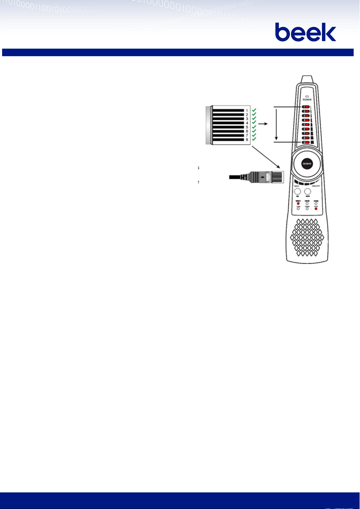
(4) Port continuity and short circuit detection:
Press “MUTE” button, when the indicator light of port is
on, the 1-8 and G indicator lights will show the continuity
of the line of the RJ45 cable connector or within 1 meter
from RJ45 cable connector. As shown on the right, If the
light is on, it means it is connected and vice versa. One
end of network cable connected to the receiver, the other
end is not connected to the emitter, press “Mute”, the
“Port” light on, can test the continuity and short circuit of
network cable.
Application: Connect one end of network cable to Switch,
and the other end connect to RJ45 port of emitter, press “SET” key to switch to the “SWITCH” mode, If the
1236 indicators light on, that is 100M switch, If 12345678 indicators light on, that is 1000M switch.
(5) The UTP port of emitter and receiver can max 60V withstand voltage, the wire can be traced directly in
connection with PoE switch
5.2 UTP detection
5.2.1 Sequence and pair line continuity detection
Step 1: Connect the network cable or telephone cable to the RJ45 port of emitter, and the other end connect to
the UTP interface of receiver. (The wire receiver needs to be turned on)
Step 2: Switch the wire tracker emitter to UTP mode, the 1-8 and G indicators will indicate the sequence of
cable, 100M and 1000M indicator will indicate whether the cable is 100M or 1000M network, the cable receiver
also can see the sequence.
Quickly determine the cable whether is normal through wire tracer emitter or wire receiver, if indicate Direct/
Cross, the cable is normal. After the 8 indicators flashed, the wire receiver will beep to indicate the type of
network cable. One sound is a straight cable, double sound is cross cable, and triple sound is another or wrong
cable.

BT-CT66 Multi-function Wire Tracker
User Manual
5.2.2 Network cable port continuity detection
In the UTP mode, press “SET” key to switch “LOCAL” mode.
Local port continuity detection: when the “LOCAL” indicator is on, connect the other end of network cable to
wire receiver “UTP” port or disconnect the UTP port, the 1-8 and G indicators indicate the continuity status of
network cable port or within 1 meter of network port which connected wire tracker emitter.
As shown in the picture below, the 1st core of network cable port on the side of emitter is disconnected, the 1st
indicator is off, it means 1st core of port is disconnected.

BT-CT66 Multi-function Wire Tracker
User Manual
Under UTP mode, press “SET” key to switch to the “REMOTE” function
Remote end continuity detection: The “REMOTE” indicator is on, connect the other end of the cable to the UTP
port of Receiver.
1-8, G indicator indicates the continuity of the cable port which connected to the Remote end (Receiver) or the
cable within 1 meter from the port. As shown in the picture below, the 5th core of the cable port on the side of
the cable tracer (receiver) is disconnected, and the 5th indicator in the 1-8 indicators is off, indicating that the
5th core of the port is disconnected and the other cores are connected.
The mid-end of cable continuity detection: If the cable sequence detects that the cores of the cable are disconnected,
and the local / remote cores are detected to be connected, indicating that the break point of the cable is in the
middle position away from the ports on both sides.
5.2.3 Short circuit test
1) Not connect receiver end
Emitter mode: The indicator lights of the short circuit
pairs are flashing
Switch mode: The indicator lights of the short-circuit
pairs are on.
2)Connect receiver end
Sequence mode: The indicator lights of the short-circuit
pair are on at the same time.
Emitter and Remote mode: The indicator lights of the
short circuit pairs are flashing.
Note: Under the port mode of receiver, the indicator
lights of the short circuit pairs are flashing.

BT-CT66 Multi-function Wire Tracker
User Manual
5.2.4 Continuity detection in the state of connected switches
Under UTP mode, press “SET” key to switch to the “SWITCH” function. When connected to a switch, 1-8, G
indicator indicates the continuity of the cable, lights on means connected, lights off means disconnected (The
100M switch is 1236 line connected, the 1000M switch is 1-8 lines connected). In this mode, connect one end of
cable to the RJ45 port of emitter, and the other end of cable disconnect to the switch, also can detect the short
circuit status of network cable, the indicator light will be on if short circuit.
5.3 PD powered detected
PoE switch or PSE power supply device connected to the “PD” port of the cable tracer, if the indicator light is
on, it means PoE voltage output working normal. There are 4 indicator lights of the “PD” port, when testing
the pins used of PoE switch for power supply, if 1236 indicator light is ON, it means PoE switch supply power
through Pin 1236. If 4578 indicator light is ON, it means PoE switch supply power through pins 4578. If 1236 and
4578 indicator lights are ON, it means device power supply through pins 1236 and 4578.
Application: Checking the pins used of PoE switch or other device for power supply, to avoid cause cannot
supply power or camera and other device damaged.

BT-CT66 Multi-function Wire Tracker
User Manual
5.4 Other features
Line DC level and positive / negative polarity testing
Turn off the emitter, the red and black wire clip of BNC cable connect to the telephone line or battery, the
other end connect to BNC port. (Note: If the telephone cable with welled RJ45 connectors, directly connect
telephone cable to RJ11 port) If the indicator light is in green, that means the red wire clip is positive, and the
black clip is negative, if the indicator light is in red, that means the black wire clip is positive, and the red wire
clip is negative. The level is higher, the indicator light is brighter, the level is lower, the indicator light is darker.
6. Specifications
Item Wire Tracker
Emit signal Digital signal(rejects noise and false signals)
Cable type RJ45 Twisted pair, RJ11 telephone line, BNC cable etc.
UTP cable test
The digital “1-8” for cable sequence shielded cable and shielding layer continuity indicator, check cable type indicator:
straight/cross/other, 100M/1000M network cable test, and near-end, mid-end, far-end continuity testing, UTP cable
short circuit test
Continuity test
of RJ45 cable
connectors
Detect the continuity of the pins on both sides of network cable and short circuits
PD (powered) test PoE switch power supplying status test and check the pins used for power supply
LED lamp ShortpressOn/OLEDlight
Silent mode Longpresskey“Mute”toswitchsilentmode,ndcablethroughindicator
Audio output Support external audio output
Power supply
External power
supply Two AA batteries
General
Working
Temperature -10℃---+50℃
Working Humidity 30%-90%
Dimension
Emitter Dimension 152mm x 62mm x 27mm /0.12KG
Receiver
Dimension 218mm x 48mm x 32mm /0.1KG
The data above is only for reference and any change of them will not be informed in advance. For more
detailed technical inquiries, please feel free to contact us.
ANKARA MERKEZ Tel: (312) 434 22 45 Faks: (312) 431 19 53
İSTANBUL Malzeme Satış Tel: (212) 347 75 40 Faks: (212) 347 75 44
İSTANBUL Network Tel: (216) 384 50 61 Faks: (216) 384 50 26
İZMİR Tel: (232) 489 07 55 Faks: (232) 425 21 49
BURSA Tel: (224) 274 00 55 Faks: (224) 273 00 26
www.bimel.com.tr [email protected]
Table of contents


