Behr Hella D-640 User manual

Bedienungsanleitung
Operating Instructions
Notice demploi
Bruksanvisning
Handleiding
Instrucciones para el manejo
Istruzioni per luso
Käyttöo je
Elektronisc er Lecksuc er D-640
Leak Detektor D-640
Désignation détecteur de fuites électronique D-640
Elektronisk läcksökare D-640
Elektronisc e Lekzoeker D-640
Detector de fugas electrónico D-640
Cercafug e elettronico D-640
Elektroninen vuototunnistin D-640

Lieferumfang
Scope of delivery
Fournitures
Leveransomfattning
Inhoud
Volumen del suministro
Kid di fornitura
Toimitussisältö
2
Lieferumfang
Scope of delivery
Fournitures
Leveransomfattning
Inhoud
Volumen del suministro
Kid di fornitura
Toimitussisältö
8PE 351 224-081
SENSOR FILTER
AC-FIL0001A
- Power +
- Power +
- Power +
- Power +

GB
DE
FI
FR
SV
NL
ES
IT
Deutsc Technische Änderungen vorbehalten Seite 4 - 8
Englis Subject to alteration without notice Page 9 - 13
Français Sous réserve de modifications techniques Page 14 - 18
Svenska Vi reserverar oss f r tekniska ändringar Sidan 19 - 23
Nederlands Technische wijzigingen voorbehouden Bladzijde 24 - 28
Español Reservadas modificaciones técniche Página 29 - 33
Italiano Con riserva modifiche tecniche Pagina 34 - 38
Suomi Oikeus teknisiin muutoksiin pidätetään Sivu 39 - 43
3

4
Benutzer andbuc
Einführung
Der Lec sucher D-640 ist zum Auffinden von Undichtig eiten in Klimaanlagen, in Verbindung mit Formiergas (95% Stic stoff, N2 / 5%Wasserstoff,
H2), onzipiert worden. Der Einsatz von Formiergas stimmt mit Arti el 6, § 3 der EU-Richtlinie 2006/40/EC überein.
Zum Auffinden von Undichtig eiten wird das leere Klimasystem mit Formiergas gefüllt. Da Wasserstoff leichter als Luft ist muss der Sensor des
Lec suchers oberhalb der vermuteten Undichtig eit (Leitungsverbindungen/Komponenten) langsam vorbeigeführt werden.
Nach beendeter Lec suche ann das Formiergas an die Umgebungsluft abgegeben werden.
Der Lec sucher D-640 besitzt langlebige beheizte Sensoren. Mit dem einzigartigen digitalen Lec anzeiger des D-640 müssen Sie nicht länger rätseln,
wie groß die Lec age ist. Das digitale Display fun tioniert unabhängig von a ustischem Alarm und der Empfindlich eitsstufe und erlaubt die genaue
Ermittlung der Lec agequelle.
Der D-640 ann entweder mit wieder aufladbaren A us oder mit 4 handelsüblichen AA-Al alizellen betrieben werden. Bei Betrieb mit A us ist auf
den orre ten Ladezustand der A us zu achten.
Beachten Sie bei der Lec suche die Sicherheitsbestimmungen und Vorgaben zum Umgang mit Kältemitteln und Druc behältern !
Fahrzeugherstellerspezifische Vorgaben sind gesondert zu beachten !

Bedienfeld
Digitaler Lec größenanzeiger
Batterieanzeige
Empfindlich eitsstufe
Stummschaltung und Empfindlich eitsstufe
Ein-/Ausschalter
Bedienungsanleitung
1. EIN-/AUSSCHALTEN: Drüc en Sie den EIN/AUS-Knopf einmal, um das
Gerät einzuschalten und noch einmal, um es auszuschalten.
2. AUFWÄRMEN: Das Gerät beginnt automatisch, den Sensor aufzuwärmen.
Während des Aufwärmens zeigt der digitale Lec größenanzeiger eine
blin ende "0" und es ertönt ein langsames "Piepen". Das Aufwärmen
dauert meist weniger als 20 Se unden.
3. BEREIT: Das Gerät ist zur Lec suche bereit, wenn die "0" aufhört,
zu blin en, und die grüne Empfindlich eits-LED aufleuchtet. Die Frequenz
des Pieptons erhöht sich und die Sensor-LED beginnt, gleichmäßig zu
blin en.
MERKMALE
Lec sucher (Modell D-640)
Zum Nachweis von Wasserstoff in Verbindung mit Fromiergas
(95 % N2, 5% H2 )
· Einzigartiger numerischer Lec größenanzeiger
· Langlebiger und stabiler Sensor
· H -Empfindlich eit < 5ppm
· Automatische Kalibrierung und automatischer Reset
· Optischer Lec agealarm mit LED nahe beim Sensor
· Drei einstellbare Empfindlich eitsstufen
· Batterieanzeige
· Echte mechanische Pumpe
· Stummschaltfun tion
· Betrieb mit 4 AA-Al alizellen
· Entspricht EN 35422 + EN 14624
· Komfortabler Sanopren-Griff
· CE-zertifiziert
5
2

Leckgrößenanzeiger
Der digitale Lec größenanzeiger ist normalerweise aus, doch wenn ein
Lec gefunden wird, wird unabhängig von der Empfindlich eitseinstellung
eine Zahl von 1 bis 9 angezeigt.
Die Zahl steigt oder fällt je nach der Menge des dete tierten Kältemittels.
Der Maximalwert wird angezeigt, wenn die Lec agequelle gefunden
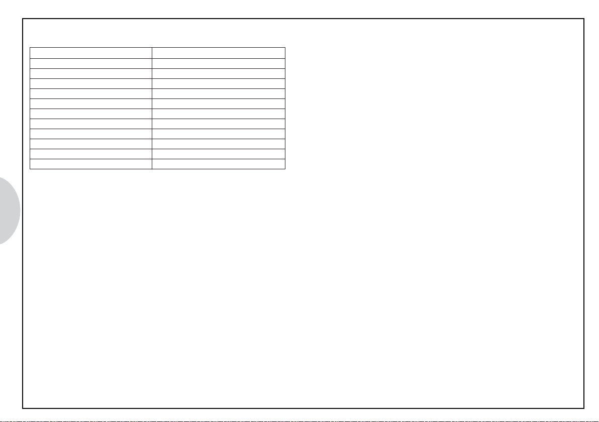
wurde. Die folgende Tabelle zeigt die ungefähre Größe des Lec s.
Angezeigter Maximalwert Lec größe in g/Jahr
1 3 < 2,83
4 6 2,83 bis 14,17
7 9 > 14,17
Batterieanzeige
Wechseln Sie die 4 AA-Al alizellen, wenn die rote LED auf dem Bedienfeld
aufleuchtet. Einlegen der Batterien siehe Abschnitt "Wartung".
tummschaltfunktion
Drüc en Sie den MUTE-Knopf, um das a ustische Alarmsignal
abzuschalten. Drüc en Sie den Knopf noch einmal, um das Signal wieder
einzuschalten. (Hinweis: Wird der MUTE-Knopf schnell hintereinander
gedrüc t, dauert es einige Se unden, bis der Ton wieder eingeschaltet
wird.)
Einstellung der Empfindlichkeit
Der Lec anzeiger befindet sich nach der Aufwärmphase automatisch
auf der Empfindlich eitsstufe NORM und die grüne LED leuchtet.
Drüc en Sie den SENS-Knopf einmal, um die Empfindlich eitsstufe auf
HI (hohe Empfindlich eit, die rote LED leuchtet) zu ändern, und noch
einmal für LO (niedrige Empfindlich eit, die gelbe LED leuchtet).
Testfläschchen zur Funktionsprüfung
Der ele tr. Lec sucher wird mit einem Testfläschchen zur Fun tionsprüfung
geliefert, mit der Sie sicherstellen önnen, dass das Gerät orre t fun tioniert.
Die Prüfung wird folgendermaßen durchgeführt:
1. Ziehen Sie die Kunststoff appe von dem Testfläschchen ab (siehe
Abbildung unten).
2. Schalten Sie den Lec anzeiger an und warten Sie, bis er sich aufgewärmt
hat.
3. Halten Sie den Sensor in die Nähe des leinen Lochs oben am
Testfläschchen. Die Piepfrequenz sollte sich erhöhen und der digitale
Lec größenanzeiger sollte eine Zahl von 4 bis 6 anzeigen, die anzeigt,
dass der Sensor und die Ele troni orre t fun tionieren.
Zum Prüfen Kappe entfernen
Testfläschchen
zur Fun tionsprüfung
HINWEIS: Vergessen Sie nicht, nach der Prüfung die Kunststoff appe
wieder aufzusetzen. Ersetzen Sie das Testfläschchen, wenn
die grüne Farbe nicht mehr sichtbar ist.
6

Wartung
Batterien
Batterien einsetzen: Lösen Sie die Schraube am hinteren Ende des
Geräts und ziehen Sie die Batterie lappe wie
gezeigt auf. Beachten Sie die Polaritätsmar ierung
innen auf der Batterie lappe zur richtigen
Installation der Batterien.
Sensor
Filter wechseln: Schrauben Sie die Sensorspitze wie gezeigt ab, um
den Filter auszutauschen. Ersetzen Sie den Filter,
sobald er sichtbar verschmutzt ist oder alle zwei bis
drei Monate, je nach Gebrauch.
Sensor austauschen: Bauen Sie den Sensor aus, indem Sie ihn aus
dem Soc el ziehen. Bauen Sie den neuen Sensor
ein, indem Sie die Kerbe im Sensordec el mit
der erhöhten Keilnut am Sensorsoc el ausrichten
(siehe Abbildung unten).
Hinweis: Drüc en Sie den Sensor nicht mit Gewalt in den Soc el.
Falsche Ausrichtung ann die Sensorstifte beschädigen.
Hinweis: Batterien und ele tr.
Geräte nicht über den
Hausmüll sondern
gesondert entsorgen
Polaritätsmar ierung
7Spitze abschrauben,
um Filter zu wechseln
Gerade abziehen
(nicht verdrehen)
Gerade aufdrüc en
(nicht verdrehen) Keilnutausrichtung
Filter
- Power +
- Power +
+ Power -
- Power +
+ Power -
8
Produktspezifikationen
Bestellnummer 8PE 351 224-081 (Modell D-640)
Bezeichnung Ele tronischer Lec sucher H2
Empfindlich eit < 5 ppm, H2
Sensorlebensdauer > 300 Stunden
Rea tionszeit Verzögerungsfrei
Spannungsversorgung 4 AA-Al alizellen
Batterielebensdauer 8 Stunden durchgehend
Aufwärmzeit < 20 Se unden
Sondenlänge 43 cm
Numerisches Display Digitale 7-Segment-Anzeige (1 bis 9)
Gewicht 680 g
Gewährleistung 2 Jahre (einschl. Sensor)
CE Zertifiziert

9
User manual
Introduction
The leak indicator D-640 is designed to detect leaks in air conditioning systems in combination with forming gas
(95% nitrogen N2 / 5% hydrogen H2). The use of forming gas complies with Article 6 § 3 of the EU Directive 2006/40/EC.
To detect leaks the empty air conditioning system is filled with forming gas. Due to the fact that hydrogen is lighter than air the sensor of the leak
indicator needs to be moved slowly above the suspected leak (electrical connections/components).
After the end of the leak search the forming gas can be released into the atmosphere.
Thanks to the unique digital leak indicator of the D-640 you longer need to guess how big the leak is. The digital display functions regardless of
the acoustic alarm and the sensitivity level and allows the source of the leak to be identified precisely.
The D-640 can be operated either with rechargeable batteries or with 4 common AA alkaline cells. Always check the correct charging level when
using rechargeable batteries.
Observe the safety regulations and the specifications relating to the handling of refrigerants and pressurised containers when searching for leaks !
Please pay special attention to the specifications of the specific vehicle manufacturers !

Operating panel
Digital leak size display
Battery charge indicator
Sensitivity level
Mute and sensitivity level keys
On/off key
Operating instructions
1. SWITCH ON/OFF: Press the ON/OFF key once to switch the device on
and once again to switch it back off.
2. WARM UP: The device automatically beings to warm the sensor up.
During warm-up an "0" flashes on the display and a slow "beep"
sounds. Warm-up usually takes less than 20 seconds.
3. READY: The device is ready for leak detection when the "0" stops
flashing and the green sensitivity LED lights up. The beeping frequency
is increased and the sensor LED starts to flash evenly.
FEATURES
Leak indicator (Model D-640) to verify hydrogen in combination with
forming gas (95% N2 / 5% H2).
· Unique numerical leak size display
· Durable and stable sensor
· Sensitivity H2 : < 5 ppm
· Automatic calibration and automatic reset
· Optical leak alarm with LED near to the sensor
· Three sensibility level settings
· Battery charge indicator
· Real mechanical pump
· Mute switch function
· Operated with 4 x AA alkali batteries
· Corresponds to EN35422 + EN14624
· Comfortable Sanoprene grip
· CE certified
10

Leak size displa
The digital leak size display is normally off but if a leak is detected a
number between 1 and 9 is displayed independently of the sensitivity
setting.
The number increases or falls depending on the quantity of refrigerant
detected. The maximum value is displayed when the source of the leak
has been found. The following table shows the approximate size of the
leak.
Maximum value displayed Size of leak in g/year
1 - 3 < 2.83
4 - 6 2.83 to 14.17
7 - 9 > 14.17
Batter charge indicator
Change the 4 AA alkali batteries when the red LED lights up on the
operating panel. See the "Maintenance "section on how to insert the
batteries.
Mute switch function
Press the MUTE key to switch the acoustic alarm signal off. Press the
key again to switch the signal on again. (Note: If the MUTE key is pressed
quickly in succession it takes a few seconds for the sound to be switched
on again.)
Setting sensitivit
Following the warm-up phase the leak detector is automatically set to
the NORM (normal) sensitivity level and the green LED is on.
Press the SENS key once to change the sensitivity level to HI (high
sensitivity the red LED lights up) and again for LO (low sensitivity the
yellow LED lights up).
Test bottle for functional test
The electrical leak detector comes with a test bottle that you can use to
make sure the device is working properly. The test is carried out as follows:
1. Pull the plastic cap off the test bottle (see the illustration below).
2. Switch the leak detector on and wait until it has warmed up.
3. Hold the sensor near the small hole at the top of the test bottle. The
beeping frequency should increase and the digital leak size display
should show a number from 4 to 6 which indicates that the sensor and
the electronics are working properly.
Remove the cap for the test
Test bottle for functional test
NOTE: Don't forget to replace the plastic cap after the test. Replace the
test bottle when the green colour can no longer be seen.
11

Maintenance
Batteries
Inserting the batteries: Loosen the screw on the rear of the device and
open the battery compartment flap as shown.
Note the polarity markings on the inside of the
battery flap for correct battery installation.
Polarity marking
- Power +
+ Power -
- Power +
+ Power -
Sensor
Changing the filter: Screw the sensor tip off as shown to replace the filter.
Replace the filter as soon as soiling is visible or every
two to three months depending on use.
Replacing the sensor: Remove the sensor by pulling it out of the base.
Insert the new sensor by aligning the notch in the
sensor cover with the raised wedge groove on the
sensor base (see illustration below).
Note: Never use force to push the sensor into the base. Incorrect alignment
can damage the sensor pins.
Note: Do not dispose of batteries
and electrical devices with
household waste heed
local regulations.
Push on straight
(do not twist)
Pull off straight
(do not twist)
Screw the tip off
to change the filter
Wedge groove alignment
12
Filter
- Power +

13
Product specifications
Order number 8PE 351 224-081 (model D-640)
Description Electronic leak detector H2
Sensitivity < 5 ppm H2
Sensor lifetime > 300 hours
Response time Without delay
Voltage supply 4 x AA alkali batteries
Battery life 8 hours continual use
Warm-up time < 20 seconds
Length of probe 43 cm
Numerical display Digital 7-segment display (1 to 9)
Weight 680 g
Warranty 2 years (incl. sensor)
CE certified
14
Notice demploi
Introduction
Le détecteur de fuites D-640 a été conçu pour la recherche de fuites dans les climatisations, en combinaison avec un gaz de formation 95 % azote,
N2 / 5 % hydrogène, H2). L'utilisation de ce mélange azote/hydrogène correspond à l'article 6, § 3 de la directive UE 2006/40/CE.
La climatisation vide est remplie du mélange azote/hydrogène afin de détecter les fuites. Etant donné que l'hydrogène est plus léger que l'air, le
capteur du détecteur de fuites doit être déplacé lentement au-dessus de la fuite présumée joints de conduite / composants).
Une fois la recherche de fuites terminée, le mélange azote / hydrogène peut être évacué dans l'air environnant.
Avec l'affichage numérique unique en son genre du D-640, vous ne devez pas chercher plus longtemps quelle est la taille de la fuite. L'écran numérique
fonctionne indépendamment de l'alarme sonore et du niveau de sensibilité et il permet une indication précise de l'origine de la fuite.
Le D-640 fonctionne avec des piles rechargeables ou bien avec 4 piles alcaline AA usuelles. Lors d'un fonctionnement avec des piles rechargeables,
veillez à un état de charge correct.
Lors de la recherche de fuites, veuillez respecter les dispositions de sécurité ainsi que les prescriptions concernant le maniement de réfrigérants et
de réservoirs sous pression ! Veuillez respecter également les prescriptions spécifiques aux véhicules !

Tableau de commandes
Affichage numérique de la taille de la fuite
Affichage du niveau des piles
Niveau de sensibilité
Passage au mode silencieux et niveau de sensibilité
Bouton marche/ arrêt
Mode demploi
1. MARCHE/ ARRET: appuyez une fois sur le bouton MARCHE/ARRET
pour allumer lappareil et une nouvelle fois pour léteindre.
2. CHAUFFAGE: lappareil commence automatiquement le chauffage des
capteurs. Pendant la phase de chauffage, un « 0 » clignote sur laffichage
numérique de la taille des fuites et un long signal sonore retentit. La
phase de chauffage dure en général moins de 20 sec. .
3. PRET: lappareil est prêt pour la détection des fuites quand le 0 arrête
de clignoter et que le LED vert de sensibilité est allumé. La fréquence
du signal sonore augmente et le LED des capteurs commence à clignoter
régulièrement.
CARACTERISTIQUES
Détecteur de fuites modèle D-640) pour la détection à l'hydrogène en
combinaison avec un gaz de formation 95% N2 / 5% H2).
· affichage numérique de la taille de la fuite unique en son genre
· capteurs stables et longue durée
· Sensibilité H2 : < 5 ppm
· calibrage et reset automatiques
· signalisation optique de fuite avec une LED à proximité du capteur
· trois niveaux de sensibilité réglables
· affichage du niveau des piles
· véritable pompe mécanique
· fonction de passage au mode silencieux
· utilisation avec 4 piles alcalines AA
· Correspond à EN35422 + EN14624
· poignée Sanoprène confortable
· certifié CE
15

A ichage de la taille des uites
Laffichage numérique de la taille des fuites est normalement éteint mais
quand une fuite est détectée un chiffre de 1 à 9 saffiche, indépendamment
du réglage de sensibilité.
Le chiffre augmente ou diminue selon la quantité de réfrigérant détectée.
La valeur maximale est affichée quand la source de la fuite a été trouvée.
Le tableau suivant montre la taille approximative de la fuite.
Valeur maximale affichée Taille de la fuite en g/ an
1 . 3 < 2,83
4 . 6 de 2,83 à 14,17
7 . 9 > 14,17
A ichage du niveau des piles
Changez les 4 piles alcalines AA quand le LED rouge sallume sur le
tableau de commandes. Insérez les piles dans lappareil comme indiqué
au point « entretien ».
Fonctionnement au mode silencieux
Appuyez sur le bouton MUTE pour éteindre le signal acoustique. Appuyez
à nouveau dessus pour rallumer le signal. remarque: si on appuie
rapidement plusieurs fois de suite sur le bouton MUTE, le son ne se
rallume quau bout de quelques secondes)
Réglage de la sensibilité
Le détecteur de uites se règle automatiquement
au niveau de sensibilité
NORM après la phase de chauffage et le LED vert est allumé. Appuyez
une fois sur le bouton SENS pour passer au niveau de sensibilité HI
très sensible, le LED rouge sallume) et encore une fois pour passer au
niveau LO peu sensible, le LED jaune est allumé).
Flacon de test pour la véri ication du onctionnement
Le détecteur de fuites électronique est livré avec un flacon de test avec
lequel vous pouvez vous assurer que lappareil fonctionne correctement.
Le test seffectue comme suit:
1. retirez le bouchon en plastique du flacon de test voir illustration ci-
dessous).
2. allumez laffichage de fuites et attendez quil ait chauffé.
3. maintenez le capteur à proximité du petit orifice en haut du flacon de
test. Le fréquence du signal sonore doit alors augmenter et laffichage
numérique de la taille de la fuite doit afficher un chiffre entre 4 et 6 ce
qui indique que le capteur et lélectronique fonctionnent correctement.
Retirer le bouchon pour effectuer une
vérification
Flacon de test pour la vérification du bon
fonctionnement de lappareil
REMARQUE: noubliez de remettre le bouchon sur le flacon après le test.
Remplacez le flacon de test quand la couleur verte nest
plus visible.
16

Entretien
Piles
Insérer les piles: dévissez la vis située en bas de lappareil et retirez le
couvercle des piles comme indiqué sur lillustration.
Veillez à respecter le marquage des pôles gravé à
lintérieur du couvercle pour installer les piles
correctement.
Marquage des pôles
Capteur
Changer le filtre: dévissez la pointe du capteur comme indiqué sur
lillustration pour échanger le filtre. Remplacez le filtre
dès quil est visiblement encrassé ou tous les deux à
trois mois, selon la fréquence dutilisation.
Changer le capteur: démontez le capteur en le tirant de son socle. Montez
le nouveau capteur en orientant lentaille de la base
du capteur en face de lentaille du socle du capteur.
voir illustration ci-dessous).
Remarque: nenfoncez pas le capteur dans le socle avec violence. La
pointe du capteur peut être endommagée si elle est enfoncée
dans le mauvais sens.
Remarque: ne pas jeter les
piles et les appareils
électriques dans les
ordures ménagères
mais séparément
17
- Power +
+ Power -
- Power +
+ Power -
Dévisser la pointe pour
changer le filtre
Tirer tout droit
ne pas tourner)
Enfoncer tout droit
ne pas tourner) Direction de lentaille
Filtre
- Power +

18
Spéci ications du produit
Numéro de commande 8PE 351 224-081 modèle D-640)
Désignation détecteur de fuites électronique H2
Sensibilité < 5 ppm, H2
Durée de vie du capteur > 300 heures
Temps de réaction sans délai
Alimentation 4 piles alcalines AA
Durée de vie des piles 8 heures daffilée
Temps de chauffage < 20 secondes
Longueur de la sonde 43 cm
Ecran numérique affichage digital à 7 segments de 1 à 9)
Poids 680 g
Garantie 2 ans capteur compris)
Certifié CE

19
Användarmanual
Presentation
Läcksökare D-640 har utvecklats för upptäckt av otätheter i klimatanläggningar í kombination med formeringsgas 95% kväve, N2 / 5% väte, H2).
Användningen av formeringsgas är i överensstämmelse med artikel 6, § 3 i EU-direktiv 2006/40/EC.
Det tomma klimatsystemet fylls med formeringsgas för upptäckt av läckor. Eftersom väte är lättare än luft måste läcksökarens sensor långsamt föras
förbi den förmodade läckan ledningsförbindninga/komponenter). Efter avslutad läcksökning kan formeringsgasen släppas ut i omgivningsluften.
Använd den unika, digitala läcksökaren D-640 och du behöver inte längre gissa dig fram till hur stor läckan är. Den digitala displayen fungerar
oberoende av det akustiska larmet och känslighetsnivån, och gör det möjigt att exakt ta reda på källan till läckan.
D-640 kan användas antingen med återuppladdningsbara batterier eller med 4 vanliga AA-alkalinebatterier. Vid användning med batterier måste man
kontrollera laddningsstatus.
Beakta säkerhetsbestämmelserna och -föreskrifterna för arbete med kylmedel och trycksatta kärl när du gör en läcksökning!
Föreskrifterna från fordonstillverkaren skall beaktas särskilt!

Användarenhet
Digital läckagedisplay
Batteriindikering
Känslighetsnivå
Tystfunktion och känslighetsnivå
På-/av-knapp
Bruksanvisning
1. INKOPPLING/AVSTÄNGNING: tryck en gång på PÅ/AV-knappen för att
sätta igång läcksökaren, och en gång till, för att stänga av.
2. UPPVÄRMNING: läcksökaren börjar värma upp sensorn automatiskt.
Under uppvärmningen visar displayen en blinkande "0" och ett långsamt
"pipljud" hörs. I regel tar uppvärmningen inte mer än 20 sekunder.
3. KLAR: läcksökaren är klar att använda när "0:an" slutar att blinka, och
den gröna känslighetslampan LED) lyser. Nu ökar frekvensen på
pipljudet och sensorlampan börjar blinka i jämn takt.
EGENSKAPER
Läcksökare modell D-640) för upptäckt av väte i kombination med
formeringsgas 95% N2 / 5% H2).
· Unik, numerisk läckagedisplay
· Stabil sensor med lång livslängd
· Känslighet H2 : < 5 ppm
· Automatisk kalibrering och automatisk återställning
· Optiskt läckagelarm med LED invid sensorn
· Tre inställbara känslighetsnivåer
· Batteriindikering
· Verklig mekanisk pump
· Tystfunktion
· Drift med 4 AA alkaliska batterier
· Motsvarar EN35422 + EN14624
· Bekvämt Sanopren-handtag
· CE-certifierad
20
This manual suits for next models
1
Table of contents
Languages:
Popular Security Sensor manuals by other brands

Honeywell
Honeywell Ex-Or MLS2000DF Installation and commissioning instructions

WHITECROFT LIGHTING
WHITECROFT LIGHTING COMRG COMMAND G Series Installation and commissioning instructions

DMP Electronics
DMP Electronics 1168 Installation and programming guide

PCB
PCB 2302-02A Installation and operating manual

Tecsis
Tecsis F9303 operating manual

Tevel
Tevel CANARY user manual


