manuals.online logo
Brands
  1. Home
  2. •
  3. Brands
  4. •
  5. Honeywell
  6. •
  7. Security Sensor
  8. •
  9. Honeywell Ex-Or MLS2000DF Installation and operation manual

Honeywell Ex-Or MLS2000DF Installation and operation manual

Installation and Commissioning
Instructions
Note: QuickSet Pro required for commissioning
HC5A available for user override
MLS Digital Detector
MLS2000DF for DSI ballasts
MLS2000DALIF for DALI ballasts
by Honeywell
MLS Digital Detector: MLS2000DF for DSI ballasts / MLS2000DALIF for DALI ballasts
Only suitably qualified personnel should install this equipment.
MLS Digital Detectors are the high-performance, communicating presence detectors at the heart of the advanced MLS
Digital lighting management system. These detectors are equipped with a regulating photocell to work with digital
DSI/DALI ballasts.
Fixing
These detectors are suitable for flush-mounting in a suspended ceiling tile, maximum 54mm thickness with a minimum
clearance of 125mm between the front surface of the tile and the hard ceiling behind and should be mounted in the centre
of the area being monitored. Cut a 50mm diameter (64mm if using an FR64 flush ring or PB64 plasterboard fixing kit)
circular hole in the tile, feed the flying leads and detector through the hole and secure in position with the locking ring.
Twist the locking ring to release the detector if necessary.
Note: Do not position within 25cm of a luminaire.
Connection
The detectors are supplied with two flying leads. The 5-core mains lead should be taken into the nearest luminaire, from
where it will pick up its 230V supply. This lead also contains connections for the polarity-free digital output (for connection
to the control input on the ballast) and the OneSwitch dimming input. The OneSwitch dimming input is sheathed for
applications which do not require this connection. This wire should be terminated safely if not being used - do not connect
to Neutral or Earth. Please see below for OneSwitch details.
The second lead contains connections for the MLS bus. The bus enables the MLS Detector to communicate with the rest
of the MLS devices in the system.
Each luminaire to be controlled must contain a digital regulating type ballast with the appropriate DSI or DALI input.
Ballast types must not be mixed. Connect all ballasts in the control group (maximum nine) in parallel and also to the
polarity-free digital output of the MLS Detector.
Each luminaire is controlled completely by its digital input and therefore would normally have a permanent power supply.
Turning the power off to some lights within a control circuit will not affect the operation of those that remain powered-up.
The MLS Bus must be connected to the MLS bus wiring network. An MLS Bus Power Supply is required for each network
of up to 200 MLS Detectors. Please refer to Bus Power Supply instructions prior to commencement of any bus wiring.
2
It is imperative that the MLS bus is wired with the correct type of cable; normally it should be 1.5mm unscreened twisted
pair. Please read Application Note AN4001 for more details. Do not connect mains to the MLS bus.
‘OneSwitch’ Dimming
OneSwitch dimming affords local control to the end-user whereby a simple, momentary, push-to-make wallswitch can be
used to raise or lower the lighting level or to toggle the output ON/OFF. A short press of the switch (less than 1 second) will
toggle the output status while a longer press will raise or lower the output. Each time the switch is pressed, the direction of
dimming reverses. If the switch has not been pressed for 5 seconds, the direction will be up (brighter) - unless the output
is already above 90% in which case the direction is down. If the switch is held continuously, and the output reaches
maximum, the light output will remain at this level until the switch is released - a latching switch may be connected in
parallel allowing the occupancy detection to be overridden on (Note: If the initial direction was down, when the output
reaches minimum it will ramp back up automatically).
Setting the Regulating Photocell
This product is intended for use with high frequency regulating ballasts with digital control inputs. An infrared
programming tool QuickSet Pro is required for programming the regulating light level set point. The setting is preserved
in the event of a power failure and can be re-programmed any number of times.
Using the QuickSet Pro, enter the Utilities menu then choose LightSpot/MLS/LCM and select ‘Set Light Level’. Use the
‘up’ and ‘down’ buttons to manually adjust the light output from the luminaire(s) and when at the required level press and
hold ‘OK’ to store. The luminaire(s) will blink to acknowledge a successful store operation.
Commissioning
Detectors are supplied factory pre-set which ensures the lighting will switch on automatically as soon as power is applied.
Final commissioning of the detectors, including assigning to zones, requires the use of the QuickSet Pro Programmer.
Please read carefully the progammer’s operating instructions prior to performing a programming operation.

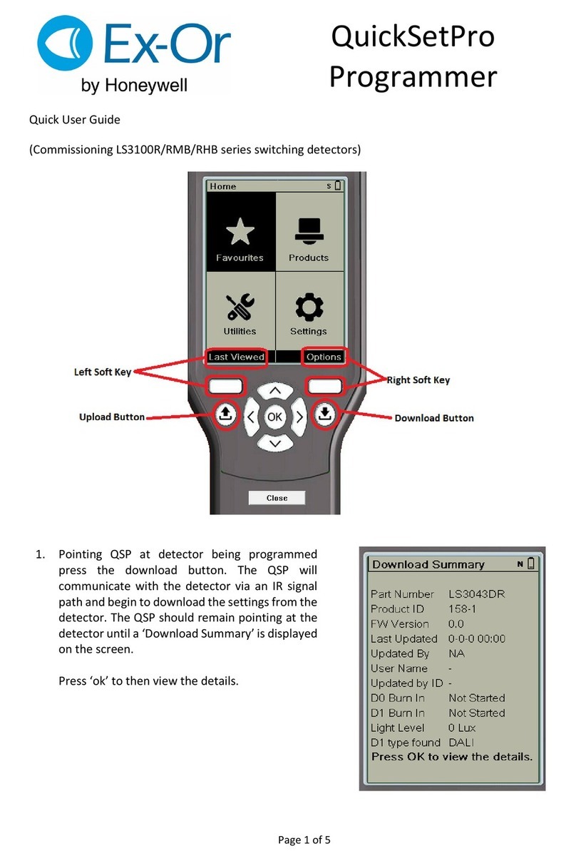
Commissioning Detectors Using the QuickSet Pro
It is important that the Programmer be held perpendicular and at a distance of between 0.5m and 2m from the detector.
1. Switch on by pressing any button (and unlock with top left rectangular button).
2. Point programmer at the detector and press the DOWNLOAD button. The programmer will confirm the product’s
identity and call up the correct menu of parameters and their current settings.
3. Use a combination of UP, DOWN, FORWARD and BACK buttons to navigate the parameter menu, selecting options
for each shown.
4. When options for all parameters have been selected, point the programmer at the detector and press the UPLOAD
button. The luminaire(s) will switch off briefly during the programming process and the programmer shows DATA
OK to confirm operation.
5. After a short period of inactivity (default 5 minutes), the programmer hibernates retaining the most recent settings.
Parameter Options Pre-Set Notes
Power Up On / Off On Sets the luminaire state at power up irrespective of occupancy.
Useful in reducing start-up load following power cut. Power-
up off - responds to occupancy after 30 seconds.
Response Auto, Manual/Bus, Manual only Auto If set to Auto, the presence detector switches the luminaire on
and off automatically. If set to Manual Only, it can only be
turned on by using OneSwitch or the hand-held controller. If
set to Manual/Bus, an MLS Bus turn-on command for a Zone
to which th
Off Delay 1 min - 96 hrs, 10-sec (walk-test), Disabled 20 mins The time for which the lum inaire will stay on following the last
detected movem ent. Also 10-second setting for walk-testing.
On Sensitivity 0-100 100 Sensitivity to movem ent when area is occupied. 100 = max
Bus Connect Yes / No Yes Do/Do not Signal/Receive on MLS Bus.
1st - 4th Zone Address 1-100; -- (no zone); Comm on 1-3 No Zone Individual Zones influencing and being influenced by this
detector.
Corridor 1 & 2 0-100; -- (no zone); Building No Zone Zone ranges influencing and being influenced by this detector.
Global 1 & 2 Rx Yes / No No Respond to selective load shedding.
Manual Input Shared / Local Local Do/Do not signal OneSwitch commands across the MLS Bus.
Start Lamps Max / Min Max Sets the level at which the lamps strike when turning on.
Entry Scene 1-6 Scene 1 Sets which scene is recalled when unoccupied area is
entered.
Bright Out Yes / No No If set to yes , movement fails to refresh the off delay if ambient
light level exceeds 125% of set level and the luminaire will
switch off when the off delay has elapsed. NB: Dimming must
be set to 100%.
Dimming Reg 50%-Reg100% 100% Can be set to operate between 50% and 100% ballast output
from max down to a bottom-end lim it when working on
photocell control.
Lamp Max 10%-100% 100% Can be set to limit the absolute maximum output of the ballast
in all operating modes.
Fade to Off Yes / No No When no presence is detected, and after the off delay period,
the lamps can fade out instead of switching off (approx 80
seconds to fade from 100% to 0%).
When Vacant Off / Min / Reg <25% / Scene 6 Off Options for a vacant area after it has timed out. Luminaires
can turn off, remain at minimum output, or regulate with a 25%
output limit, until the next period of occupancy. If programmed
to remain at minimum, to regulate below 25% or go to scene
6, the
Set-point Low 0-1023 1023 Aiming point as photocell adjusts ballast output.
Set-point High 0-1023 1023 Level above which photocell switches its output off (only if
Bright Out = Yes).
100 Hour Burn-In Burn-in 100 hrs / Cancel / Resume 0 hr See Application Note: AN4028
Additional feature accessible under Utilities on QuickSet Pro:
W4232H
Electrical Connections
Technical Data
2
MLS CABLE: 1.5mm unscreened twisted-pair : see Application Note AN4001
RECOMMENDED MAXIMUM MOUNTING HEIGHT: 3.0m
RANGE: Cone-shaped detection pattern,
diameter (at floor level)
= 2.4 x mounting height
OPERATING VOLTAGE: 230V 50Hz (UK & Europe)
PRODUCT RATING & RECOMMENDED CIRCUIT PROTECTION: 10 Amps
CAPACITY: 9 ballasts
OUTPUT: 2-wire digital polarity free-max extended cable length: 12m
PHOTOCELL: Regulating
OFF DELAY: Adjustable via Programmer - factory pre-set to 20 minutes
DEPTH REQUIRED BEHIND CEILING: 125mm
WEIGHT: 370g incl. 3m cable at 100g/m
COLOUR: White
MATERIAL: Flame retardant PC/ABS
IP RATING: 4X
o o
OPERATING TEMPERATURE: 0 C to 40 C
Important Additional Notes
1. A means for disconnection must be incorporated in the fixed wiring in accordance with the current wiring regulations.
2. Although nominally 12V, the dimming output is not SELV and therefore should be treated with the same respect as mains with regard to wiring
practice. The 0V line of the dimming output is almost at Neutral potential.
3. The dimming control output should be connected only to the control input of the ballasts - never to other detectors.
4. This equipment should be used to control only those ballasts powered from the same phase as the detector.
5. Due to the fact that the photocell is on the ceiling looking down, it is not possible for measurements made with a lux meter on the working plane to
remain constant when daylight illuminates the ceiling and the working plane to a differing extent. Therefore, products of this type should be
regarded as capable of maintaining an APPROXIMATE light level only.
6.0m
2.5m
115mm
65mm
Supply
230V
50Hz
Push-to-Make
Mains-Rated
Retractive Switch
OneSwitch
Input
(see overleaf)
Brown
Blue
Orange
White
Grey
Violet
Polarity-free
Digital Output
MLS
Bus
Red
L
N
At the end of their useful life
the packaging and product
should be disposed of via a
suitable recycling centre.
Do not dispose of with normal
household waste.
Do not burn.
Honeywell Ex-Or
St. Mark’s Court, North Street, Horsham,
West Sussex, RH12 1BW UK
Tel: + 44 (0)1942 719229
Email: technicalsales.ex-or@honeywell.com
www.ex-or.com

This manual suits for next models

1

Other Honeywell Security Sensor manuals

Honeywell IRV800M User manual

Honeywell

Honeywell IRV800M User manual

Honeywell DT7235T User manual

Honeywell

Honeywell DT7235T User manual

Honeywell Ex-Or MR2500D Installation and operation manual

Honeywell

Honeywell Ex-Or MR2500D Installation and operation manual

Honeywell FS20X Series User manual

Honeywell

Honeywell FS20X Series User manual

Honeywell Activ8 PIR User manual

Honeywell

Honeywell Activ8 PIR User manual

Honeywell IntelliSense FG-1625RFM User manual

Honeywell

Honeywell IntelliSense FG-1625RFM User manual

Honeywell Peha D MLS2001AF Installation and operation manual

Honeywell

Honeywell Peha D MLS2001AF Installation and operation manual

Honeywell RAEGuard 2 PID User manual

Honeywell

Honeywell RAEGuard 2 PID User manual

Honeywell FG-730 User manual

Honeywell

Honeywell FG-730 User manual

Honeywell C7076A User manual

Honeywell

Honeywell C7076A User manual

Honeywell Lyric W1 User manual

Honeywell

Honeywell Lyric W1 User manual

Honeywell SC100 User manual

Honeywell

Honeywell SC100 User manual

Honeywell Miller Stopfall 7700A/YL/GP-1 Operator's manual

Honeywell

Honeywell Miller Stopfall 7700A/YL/GP-1 Operator's manual

Honeywell Small SATCOM Instruction Manual

Honeywell

Honeywell Small SATCOM Instruction Manual

Honeywell Viewguard DUAL AM FAI User manual

Honeywell

Honeywell Viewguard DUAL AM FAI User manual

Honeywell W1KS User manual

Honeywell

Honeywell W1KS User manual

Honeywell NFPA 1971 Owner's manual

Honeywell

Honeywell NFPA 1971 Owner's manual

Honeywell Miller Titan TR50 User manual

Honeywell

Honeywell Miller Titan TR50 User manual

Honeywell 5800PIR User manual

Honeywell

Honeywell 5800PIR User manual

Honeywell C7061A Operation manual

Honeywell

Honeywell C7061A Operation manual

Honeywell Miller TurboLite Series Operator's manual

Honeywell

Honeywell Miller TurboLite Series Operator's manual

Honeywell Ex-Or MLS2021DF Installation and operation manual

Honeywell

Honeywell Ex-Or MLS2021DF Installation and operation manual

Honeywell AreaRAE Plus User manual

Honeywell

Honeywell AreaRAE Plus User manual

Honeywell Miller QuickPick Rescue Kits Operator's manual

Honeywell

Honeywell Miller QuickPick Rescue Kits Operator's manual

Popular Security Sensor manuals by other brands

Pneumercator LLP203 instruction manual

Pneumercator

Pneumercator LLP203 instruction manual

ITALIANA SENSORI 8001-ISR001 Installation, operation and maintenance manual

ITALIANA SENSORI

ITALIANA SENSORI 8001-ISR001 Installation, operation and maintenance manual

Potter PAD300-4DB quick start guide

Potter

Potter PAD300-4DB quick start guide

Pepperl+Fuchs KFD2-ELD-Ex16 manual

Pepperl+Fuchs

Pepperl+Fuchs KFD2-ELD-Ex16 manual

iRay Technology Mars1417X user manual

iRay Technology

iRay Technology Mars1417X user manual

Greenlee 170XL user manual

Greenlee

Greenlee 170XL user manual

Toshiba LF664 instruction manual

Toshiba

Toshiba LF664 instruction manual

PCB Piezotronics 138A06 Installation and operating manual

PCB Piezotronics

PCB Piezotronics 138A06 Installation and operating manual

teko Astra-8 user guide

teko

teko Astra-8 user guide

Velleman PIR700 user manual

Velleman

Velleman PIR700 user manual

Sinope WL4200C quick start guide

Sinope

Sinope WL4200C quick start guide

Doepke Dupline DBM 1 operating instructions

Doepke

Doepke Dupline DBM 1 operating instructions

PCB Piezotronics IMI SENSORS TO641B31 Installation and operating manual

PCB Piezotronics

PCB Piezotronics IMI SENSORS TO641B31 Installation and operating manual

Eaton CEAG 6811 LED CGLine+ Mounting and operating instructions

Eaton

Eaton CEAG 6811 LED CGLine+ Mounting and operating instructions

Bartington Mag900 Operation manual

Bartington

Bartington Mag900 Operation manual

System Sensor B200SR Installation and maintenance instructions

System Sensor

System Sensor B200SR Installation and maintenance instructions

Schmidt SS 20.420 Instructions for use

Schmidt

Schmidt SS 20.420 Instructions for use

Valcom OMD Series operating manual

Valcom

Valcom OMD Series operating manual

manuals.online logo
manuals.online logoBrands
  • About & Mission
  • Contact us
  • Privacy Policy
  • Terms and Conditions

Copyright 2025 Manuals.Online. All Rights Reserved.