manuals.online logo
Brands
  1. Home
  2. •
  3. Brands
  4. •
  5. Behringer
  6. •
  7. Amplifier
  8. •
  9. Behringer Ultravoice Digital VX2496 User manual

Behringer Ultravoice Digital VX2496 User manual

Users Manual
Version 1.1 September 2003
ENGLISH
ULTRAVOICE
DIGITAL VX2496
2
ULTRAVOICE DIGITAL VX2496
This symbol, wherever it appears, alerts you to the
presence of uninsulated dangerous voltage inside
the enclosurevoltage that may be sufficient to
constitute a risk of shock.
This symbol, wherever it appears, alerts you to
important operating and maintenance instructions
in the accompanying literature. Please read the
manual.
SAFETY INSTRUCTIONS
CAUTION: To reduce the risk of electric shock, do not remove
the cover (or back). No user serviceable parts
inside refer servicing to qualified personnel.
WARNING: To reduce the risk of fire or electric shock, do not
expose this device to rain and moisture.
DETAILED SAFETY INSTRUCTIONS:
1) Read these instructi ns.
2) Keep these instructi ns.
3) Adhere t all warnings.
4) F ll w all instructi ns.
5) D n t use this device near water.
6) Clean nly with a dry cl th.
7) D n t bl ck any ventilati n penings. Install in
acc rdance with the manufacturers instructi ns.
8) D n t install near any heat s urces such as radiat rs,
heat registers, st ves, r ther apparatus (including
amplifiers) that pr duce heat.
9) D n t defeat the safety purp se f the p larized r
gr unding-type plug. A p larized plug has tw blades
with ne wider than the ther. A gr unding type plug
has tw blades and a third gr unding pr ng. The wide
blade r the third pr ng are pr vided f r y ur safety. If
the pr vided plug d es n t fit int y ur utlet, c nsult
an electrician f r replacement f the bs lete utlet.
10) Pr tect the p wer c rd fr m being walked n r
pinched particularly at plugs, extensi n c rds, and the
p int at which they exit the equipment.
11) Only use attachments/access ries specified by the
manufacturer.
12) Use nly with the cart, stand, trip d, bracket, r table
specified by the manufacturer, r s ld with the device.
When a cart is used, use cauti n when m ving the cart/
device c mbinati n t av id injury fr m stumbling ver
it.
13) Unplug this piece f equipment during lightning
st rms r when n t used f r l ng peri ds f time.
14) Refer all servicing t qualified service pers nnel.
Servicing may be required when this piece f equipment
has been damaged in any way, such as when p wer
supply c rd r plug is damaged, liquid has been spilled
r bjects have fallen inside, it has been exp sed t rain
r m isture, it d es n t perate n rmally, r has been
dr pped.
3
ULTRAVOICE DIGITAL VX2496
VX2496
ULTRAVOICE DIGITAL
Professional High-Performance Mic Preamplifier Voice Processor with AES EBU Output
HIGH
–
RESOLUTION 24
–
BIT/
96 kHz CONVERTER
sUltra low-noise discrete vintage-design mic/line input stage
s24-bit A S/ BU output with selectable 44.1, 48, 88.2 and 96 kHz sampling rates or external clocking
sAuthentic tube emulation circuitry for typical tube and tape saturation sounds
sTrue RMS expander for extremely smooth noise reduction
sOpto compressor for inaudible level control and creative sound processing
sIntegrated dynamic enhancer compensates for high-frequencies lost through compression
sVoice-optimized equalizer specially designed for voice enhancement
sOpto de-esser for quick removal of excessive sibilance from your vocal track
sHigh-performance VCAs for ultimate signal purity
sUltra low-noise 4580 operational amplifiers for outstanding audio performance
sAccurate L D metering for crystal-clear level and processor indication
sServo-balanced gold-plated XLR connectors for all main inputs and outputs
sUltra high-precision ALPS® potentiometers for ultimate accuracy and repeatability
sIlluminated switches ensure perfect operation in dark stage environments
sHigh-quality components and exceptionally rugged construction for long life and durability
sShielded toroidal power transformer for lowest noise interference
sDesigned in Germany. Manufactured under ISO9000 certified management system
4
ULTRAVOICE DIGITAL VX2496
1. INTRODUCTION
Thank you for the confidence you have placed in us by
purchasing the ULTRAVOICE DIGITAL VX2496. With the
ULTRAVOICE DIGITAL you have acquired an extremely powerful
device for creatively processing your music. Its professional
design means the VX2496 can produce excellent results, both in
the studio and live. Numerous features, such as the opto
compressor or the voice-optimized EQ mean you can even
process signals with a very wide dynamic range and tailor them
to the overall sound of your music. In addition, the VX2496 has a
digital AES/EBU output with a high-resolution 24-bit/96 kHz A/D
converter and a wordclock input enabling synchronization to
external devices.
The BEHRINGER ULTRAVOICE DIGITAL combines a microphone
preamp, control amplifier and equalizer and is ideally suited for
connection to a hard disk recording system where you could,
for example, record vocals directly onto the hard drive. The
highest quality is maintained, as any potential deterioration caused
by inserting into a mixing console is eliminated. In addition, the
integrated A/D converter ensures optimum conversion of the
analog signal with no degradation of sound quality. And, due to
its professional signal-processing features, the ULTRAVOICE
DIGITAL is also the ideal tool for optimizing live vocals.
To familiarize yourself with the functions of the VX2496, simply
connect any audio signal and try out each individual control. Use
a relatively uncompressed signal (for example, one of your own
recordings) in order to judge the effect of the opto-compressor.
CDs are usually pre-compressed, which makes it difficult to
hear how the compressor changes the sound.
Dear Customer,
welcome to the team of
BEHRINGER users and
thank you very much for
expressing your confi-
dence in us by purchasing
the VX2496.
Writing this foreword for
you gives me great
pleasure, because it
represents the cul-
mination of many months
of hard work delivered
by our engineering team
to achieve a very am-
bitious goal: to offer you
a high-quality device
whose flexibility makes
it suitable for use both in
studios and in the P.A.
rental market.
The task of designing our new ULTRAVOICE DIGITAL VX2496
certainly meant a great deal of responsibility which we assumed
by focusing on you, the discerning user and musician. Meeting
your expectations also meant a lot of work and night shifts. But
it was fun, too. Developing a product usually brings a lot of
people together, and what a great feeling it is when all who
participated in such a project can be proud of what theyve
achieved.
It is our philosophy to share our enjoyment with you, because
you are the most important member of the BEHRINGER team.
5
ULTRAVOICE DIGITAL VX2496
2. CONTROL L M NTS
Once you have developed a feel for the individual components,
you can unleash your creativity by combining individual functions.
+This manual first describes the termin l gy used,
s that y u fully understand the VX2496 and its
functi ns. Please read the manual carefully and keep
it f r future reference.
1.1 Before you get started
Your ULTRAVOICE DIGITAL was carefully packed in the
factory, and the packaging is designed to protect the unit from
rough handling. Nevertheless, we recommend that you carefully
examine the packaging and its contents for any signs of physical
damage, which may have occurred during transit.
+If the unit is damaged, please d NOT return it t
BEHRINGER, but n tify y ur dealer and the shipping
c mpany immediately. Otherwise, claims f r damage
r replacement may n t be granted.
Be sure that there is enough space around the unit for cooling
and, to avoid overheating, please do not place your
ULTRAVOICE DIGITAL on power amplifiers, etc.
The mains connection is via the enclosed power cord and a
standard IEC receptacle. It meets all international safety
certification requirements.
+Please make sure that all units have a pr per
gr und c nnecti n. F r y ur wn safety, never
rem ve r disable the gr und c nduct r fr m the
unit r the AC p wer c rd.
Bef re y u c nnect y ur ULTRAVOICE DIGITAL t the
mains, please make sure that the v ltage setting n
y ur unit matches the l cal v ltage! The fuse holder above
the AC power connector has 3 triangular markings. Two of
these three triangles are aligned with one another. The VX2496
is set to the voltage shown next to these markings and can be
switched over by turning the fuse holder by 180°. IMPORTANT:
This d es n t apply t exp rt m dels designed exclusively
f r 120 V perati n!
2. CONTROL ELEMENTS
2.1 Discrete vintage input stage
Fig. 2.1: Discrete Vintage input stage
This secti n f the ULTRAVOICE DIGITAL is a preamp
where y u regulate the input level f the micr ph ne r
line level signal.
Use the LINE button to select the type of input signal
(pressed = LINE, not pressed = MIC).
Press the +48 V button to power a condenser microphone.
Dynamic microphones do not require this phantom power
supply.
The GAIN control sets the input level. The scale -12 to
+12dB relates to the LINE input whereas the scale +10 to
+60dB relates to the MIC input.
The SIG LED above the gain control illuminates when an
input signal is present.
Ensure that the CLIP LED lights up only with peak signals.
If it is constantly lit or if distortion can be heard, reduce the
input level using the GAIN control.
The ULTRAVOICE DIGITAL has a low-cut filter which can
be used to remove low-frequency interference from the
microphone signal. This function is activated with the
L CUT button. This filter has a slope of 12 dB/oct.
With the FREQUENCY control, you can select the cutoff
frequency below which the low-frequency component will
be removed (range 15 - 360 Hz).
The Ø INV shifts the input signal phase by 180°. Use this
function if the use of multiple microphones results in
cancellations of specific frequency ranges.
2.2 Expander and tube emulation
6
ULTRAVOICE DIGITAL VX2496
2. CONTROL L M NTS
The TUNING control lets you determine the frequency range
to be saturated. All other ranges remain unaffected,
allowing the effect to be finely tailored.
To process the whole frequency spectrum, use the FULL
BW button. This makes the TUNING control inoperative.
2.3 Opto compressor
7
ULTRAVOICE DIGITAL VX2496
3. R CORDING WITH TH ULTRAVOIC DIGITAL
+T av id c l ring the character f the s und, d n t
set the thresh ld t l w when using the pt
de-esser. When the thresh ld is set at its ptimal
value, the effect sh uld nly be rec gnizable by
direct c mparis n t the unpr cessed signal using
the IN/OUT butt n.
Use the MASTER FADER to match the output signal level
to the input sensitivity of the following device (e.g. your
DAT or hard disk recorder).
+Start by tuning the master fader right d wn and
increase it sl wly t the desired level. If y u start
with t high a level, y u risk verl ading the inputs
f the devices that f ll w!
The six UTPUT LEVEL LEDs show the level of the output
over a -10 to +15 dB range. Ensure that the output level
does not go into overload otherwise the signal at the
DIG OUT output will be too high and cause distortion.
Use the P WER button to turn on the ULTRAVOICE DIGITAL.
2.6 Rear panel connectors
8
ULTRAVOICE DIGITAL VX2496
5. LIV APPLICATIONS WITH TH ULTRAVOIC DIGITAL
3) If necessary you can then smooth out the dynamics of the
vocal slightly with the opto compressor. Be sure not to
compress the signal too much the compressor can always
be used again after the recording. Also, do not use the
hard ratio function at this stage as it makes a very audible
difference in the signal. If the vocalist constantly changes
his distance from the microphone during recording, extreme
dynamic fluctuations may result. In this case, a higher
level of compression should be used. Keep the threshold
relatively low on the opto compressor to obtain a normal
volume level.
+T av id having t c mpress the signal t much,
try t maintain a c nstant distance between the
v calist and the micr ph ne while rec rding.
Backing vocals should be highly compressed so they can be
present throughout the recording without volume fluctuations.
4) The voice-optimized EQ allows you to equalize deficiencies
in the sound image that could not be corrected in advance.
However, do not use extreme settings here either, as you
can add more EQ when mixing. The voice-optimized EQ
can be used to deal with the following problems:
sIf the v cals s und muddy in the bass range, y u
can cut the l w-frequency area f the signal by using
the WARMTH c ntr l. Set the c ntr l t full cut and
l cate the intrusive frequency range with the TUNING
c ntr l s that the v ice s unds m re balanced.
Y u sh uld try this in s l m de first. Then, listen
t the v ice with the rest f the mix and adjust the
WARMTH c ntr l until the verall s und is right.
sIf the v ice s unds t edgy, use the ABSENCE butt n
n the v ice- ptimized EQ. This will attenuate these
harsh frequencies with ut c mpr mising the natural
quality f the verall s und. In additi n, y u can b st
the l w frequencies with the WARMTH c ntr l r, if
necessary, impr ve the peaky characteristic f the
signal by l wering the BREATH r PRESENCE c ntr l.
sIf the v ice is getting l st in the mix, increase the
PRESENCE c ntr l. B sting this range will help the
v ice t cut thr ugh m re.
sIf the v cal s und is n t brilliant en ugh, y u can
add peaks using either the PRESENCE r the
BREATH c ntr l. Additi nally, y u can use the
pt -c mpress r enhancer t add upper harm nics
artificially.
5) If the signal contains unwanted frequency areas, use the
expander and the opto de-esser to remove them. Sibilance
can be removed with the opto de-esser, but first you must
isolate the intrusive frequency range:
sActivate the v ice- ptimized EQ and turn the BREATH
c ntr l up t exaggerate sibilant frequencies. If y u
have already used the EQ, first make a n te f the
riginal settings s they can be subsequently reset.
sActivate the pt de-esser and, using a l w
thresh ld, turn the CUT FREQ c ntr l until the
sibilance is reduced.
sN w turn the v ice- ptimized EQ ff again and reset
the BREATH c ntr l t its riginal p siti n.
sN w set the thresh ld s the ACTIVE LED nly lights
up when sibilance is present.
The expander enables you to remove intrusive noise from
quiet passages. To do this, turn the THRESHOLD control to the
far left and turn it up slowly with DEPTH set at medium. Find the
value at which you notice an audible suppression of the quiet
spots without impairing the vocal sound.
Only use the gate in exceptional casesif, for instance, you
want to achieve a specific effect. It radically affects the sound
and could thus ruin your recording.
6) Use the tube emulation for a classic analog tape recording
sound.
7) Finally, use the MASTER FADER to regulate the
ULTRAVOICE DIGITALs output.
4. MIXING WITH THE
ULTRAVOICE DIGITAL
Go ahead and experiment with the mixing possibilities of the
ULTRAVOICE DIGITAL and push it to its limits. It is often the case
that extreme effect and filter settings are needed to optimally
integrate a signal into the mix. If a voice ultimately appears as
very full and present in the mix, it usually means the signal has
been thoroughly and truly tweaked.
Vocals usually have reverb added during the mix. If you notice
intrusive noise (e.g. sibilance) in the reverb, use the opto
de-esser to remove it as follows:
sRem ve the sibilance fr m the v cal as previ usly
described in chapter 3.5 and drive the reverb unit
via ne f the main utputs (n t via the INSERT path
as it is s urced bef re the de-esser). Make sure
the reverb unit is set t 100% wet, i.e. there is n
dry direct signal present.
sThe reverb signal can n w be mixed at the c ns le
with the signal fr m the VX2496s RECORDING utput.
This is s urced bef re the de-esser, and in this
way sibilance is rem ved nly fr m the reverb
signal, n t the main v ice itself.
The expander can be used to remove spill from other
instruments which, for example, may have been picked up by
the microphone from the vocalists headphones. Remember that
compression would have the opposite effect, as the signal is
limited at the loudest spots. Any spill would then become
effectively louder.
Although the ULTRAVOICE DIGITAL was principally designed
to record vocals, you can of course also use it to record and mix
other signals.
4.1 Hints about analog output level setting
The output level meter has been calibrated to +4 dBu. For Main
Out, this means the following: if OUTPUT LEVEL METER shows
0 dB, +4 dBu is connected to Main Out. This way, you have
positioned the optimal level of the output signal in order to create
maximum rejection with sufficient headroom.
Hint: Some equipment requires a lower input signal level
(-10 dBV in home recording domain). Use the input signal level
displays of such equipment as well as the output level control of
the VX2496 to create optimal adjustments.
4.2 Hints about digital output level setting
The maximum level for digital signals is 0 dBFS. If the OUTPUT
LEVEL-LEDs indicate +15 dB, this signal level is located at the
digital output of the VX2496. Always keep in mind that a signal
level higher than 0 dBFS/+15 dB will immediately lead to harsh
distortion. Therefore, we suggest that you always stay well
below this value in order to avoid distortion and increase
headroom for signal peaks.
+Please always make sure that the clip LED at the
input is seld m r never lit.
5. LIVE APPLICATIONS WITH THE
ULTRAVOICE DIGITAL
The ULTRAVOICE DIGITAL is a versatile problem-solver and
sound-shaper both in live and studio environments.
On a small stage, short distances between the microphone
and the monitor speaker can lead to unpleasant feedback. In this
case the VX2496 opto de-esser could be used to suppress
feedback:
sSet the THRESHOLD c ntr l relatively l w.
sUse the CUT FREQ c ntr l t find the frequency
causing the feedback.
sN w turn the thresh ld up far en ugh t eliminate
the feedback while maintaining an unaffected v cal
signal as much as p ssible.
9
ULTRAVOICE DIGITAL VX2496
7. AUDIO CONN CTIONS
Loud volume can lead to large amounts of spill on stage, i.e.
the microphones do not just pick up one signal (e.g. vocal), but
many other signals from the stage. This can be a major problem,
as the individual signals cannot be easily controlled independently.
Use the expander to isolate individual signals and to lessen of
spill. The level of the spill is lowered while the louder wanted
signal is unaffected. The gate function also lends itself well to
this application as unwanted signals can be completely eliminated
in this way. You must be careful, however, to ensure that the
main signal is not clipped as the gate cuts off when it falls below
the threshold. This could even cause quiet passages to disappear
even though they are meant to be heard. The gate is also ideally
suited to processing impulse sounds (e.g. snare, bass drum,
toms etc.) as these are relatively short signals that neither swell
nor ring out.
6. INTEGRATION INTO A RECORDING
SYSTEM
As mentioned at the beginning of this manual, the
ULTRAVOICE DIGITAL is ideally suited to direct connection to a
recording medium, such as a DAT recorder, analog tape machine,
or even a hard disk recording system without the use of a mixing
console. Furthermore, an extremely clean signal is produced as
the potential noise produced by looping through a mixing console
is eliminated from the outset. You can integrate the VX2496 into
a hard disk recording system without having to use an additional
A/D converter. For such cases, the ULTRAVOICE DIGITAL has a
24-bit/96 kHz A/D converter with digital AES/EBU output. The
wordclock input allows the VX2496 to be locked to external
devices. Of course, you can also successfully integrate the
ULTRAVOICE DIGITAL into your studio conventionally with a
mixing console.
7. AUDIO CONNECTIONS
The BEHRINGER ULTRAVOICE DIGITAL VX2496 hasexcept
for the insert connectorsstandard electronically servo-
balanced inputs and outputs. The circuit design has automatic
hum suppression with balanced signals and operates problem
free even at high levels. Externally-induced mains hum is thus
efficiently suppressed. The servo-function automatically detects
when connector pins are unbalanced and changes the nominal
level internally by 6 dB so that there is no difference in level
between input and output signals.
+Please ensure that nly qualified pers ns install
and perate the device. During installati n and
perati n the user must have sufficient electrical
c ntact t earth. Electr static discharges might
affect the perati n f the unit.
10
ULTRAVOICE DIGITAL VX2496
8. SP CIFICATIONS
. SPECIFICATIONS
AUDIO INPUTS
MIC XLR connector, HF shielded, balanced
Line XLR connector and 1/4" jack
HF shielded, balanced
Insert Return 1/4" jack unbalanced
Impedance
MIC 1. 3 kΩ unbalanced, 2.6 kΩ balanced
Line XLR connector and 1/4" jack
10 kΩ unbalanced, 20 kΩ balanced
Insert Return 10 kΩ unbalanced
Max. Input Level
MIC +11 dBu unbalanced and balanced
Line XLR and jack +21 dBu balanced
and unbalanced
Insert Return +21 dBu
CMRR typical 40 dB, >60 dB @ 1 kHz
(except Insert Return)
AUDIO OUTPUTS
Recording Out XLR Electronically controlled servo-balanced
output stages
Main Out XLR Electronically controlled servo-balanced
output stages
Main Out Jack 1/4" jack unbalanced
Impedance
Rec. Out 120 Ω balanced, 60 Ω unbalanced
@ 1 kHz
Main Out XLR 120 Ω balanced, 60 Ω unbalanced
@ 1 kHz
Main Out Jack 100 Ω unbalanced @ 1 kHz
Insert Send 100 Ω unbalanced @ 1 kHz
Output Level
Rec. Out max. +21 dBu balanced and unbalanced
Main Out XLR max. +21 dBu balanced and unbalanced
Main Out Jack max. +21 dBu unbalanced
Insert Send max. +21 dBu unbalanced
SYSTEM DATA
Bandwidth 20 Hz to 20 kHz, +0/-0.6 dB
Frequency Response Line: <10 Hz to >200 kHz,
+0/-1.7 dB -> Main Out
MIC: <10 Hz to >200 kHz,
+0/-2.5 dB -> Main Out
S/N Ratio 123.6 dB dynamics -> Insert Send
118.5 dB dynamics -> Main Out
122 dB dynamics -> Recording Out
130 dB E.I.N, Mic In -> Insert Send
105 dB Line -> Insert Send @ +4 dBu/1 kHz
THD 0.006% typ. @ -30 dBu, 1 kHz,
Gain 30 dB, Mic In -> Insert Send
0.01% typ. @ -30 dBu, 1 kHz,
Gain 30 dB, Mic In -> Main Out
0.001% typ. @ +4 dBu, 1 kHz,
Unity Gain, Line In -> Insert Send
0.004% typ. @ +4 dBu, 1 kHz,
Unity Gain, Line In -> Main Out
DIGITAL OUTPUT
Type High-resolution 24-bit AKM A/D converter
Standard AES/EBU / XLR transformer-balanced
Output Impedance 110 Ω balanced
Nom. Output Level 5 V peak-to-peak
INTERNAL SAMPLING FREQUENCY
44.1 / 48 / 88.2 / 96 kHz (switchable)
WORDCLOCK INPUT
Type BNC
Frequency Range 31 to 100 kHz
Input Impedance 100 kΩ
Nom. Input Level 2 to 5 V peak-to-peak
EXPANDER/GATE SECTION
Type RMS Expander
Threshold variable (OFF to +10 dB)
Ratio Expander: variable (1:1 to 3:1)
Gate: 1:oo
Attack <1 msec / 20 dB, fixed
Release 100 msec / 20 dB, fixed
COMPRESSOR SECTION
Type Opto Compressor
Threshold variable (-25 to +10 dB)
Ratio switchable (3:1 / 9:1)
Manual Release Time variable (10 dB / 10 msec
to 10 dB / 1.5 sec)
Manual Attack Time 10 dB / 10 msec
Fast: 20 dB / 10 msec
Output variable (0 bis +20 dB)
DE-ESSER SECTION
Type VAD (Voice-Adaptive)-De-Esser
Filter Frequency 2.7 to 12 kHz
Filter Quality program-dependent, max. Q = 4
Attenuation max. 18 dB
TUBE EMULATION SECTION
Filter Frequency variable, 800 Hz to 12kHz
Peak Frequency
Full Bandwidth,
lower Cut-off Frequency = 200 Hz
Characteristic Band Pass, 1st Order
(6 dB/Oct.)
Full Bandwidth:
High Pass, 1st Order
(6 dB/Oct.)
Boost variable, max. 20 dB
VOICE OPTIMIZED EQ SECTION
Bands 3
Filter Quality Boost: 0.4 / Cut: 3
Filter Frequencies Breath: Type shelving,
lower Cut-off Frequency 10 kHz
Presence: Type peak,
Peak Frequency 1.5 kHz
Warmth: Type peak,
semiparametric
Peak Frequency variable from
130 to 720 Hz
POWER SUPPLY
Mains voltage USA/Canada
120 V~, 60 Hz
Europe/U.K./Australia
230 V~, 50 Hz
Japan
100 V~, 50 - 60 Hz
General export model
120/230 V~, 50 - 60 Hz
Power Consumption max. 25 W
Fuse 100 - 120 V~: T 630 mA H
200 - 240 V~: T 315 mA H
Mains Connection Standard IEC Receptacle
DIMENSIONS (H x W x D) approx. 1 ¾" (44.5 mm) x
19" (482.6 mm) x 8 ½" (217 mm)
WEIGHT approx. 2.2 kg
SHIPPING WEIGHT approx. 3.4 kg
BEHRINGER makes every effort to ensure the highest standard of quality. Necessary
modifications are carried out without notice. Thus the specifications and design of the device
may differ from the information given in this manual.
11
ULTRAVOICE DIGITAL VX2496
9. WARRANTY
The information contained in this manual is subject to change without notice. No part of this manual may be reproduced or
transmitted in any form or by any means, electronic or mechanical, including photocopying and recording of any kind, for any
purpose, without the express written permission of BEHRINGER Spezielle Studiotechnik GmbH.
BEHRINGER is a registered trademark. ALPS® is a registered trademark of the respective owner, which is in no way associated
or affiliated with BEHRINGER. ALL RIGHTS RESERVED.
© 2003 BEHRINGER Spezielle Studiotechnik GmbH.
BEHRINGER Spezielle Studiotechnik GmbH, Hanns-Martin-Schleyer-Str. 36-38, 47877 Willich-Münchheide II, Germany
Tel. +49 2154 9206 0, Fax +49 2154 9206 4903
9. WARRANTY
§ 1 WARRANTY CARD/ONLINE REGISTRATION
To be protected by the extended warranty, the buyer must
complete and return the enclosed warranty card within 14 days
of the date of purchase to BEHRINGER Spezielle Studiotechnik
GmbH, in accordance with the conditions stipulated in § 3. Failure
to return the card in due time (date as per postmark) will void any
extended warranty claims. Based on the conditions herein, the
buyer may also choose to use the online registration option via
the Internet (www.behringer.com or www.behringer.de).
§ 2 WARRANTY
1. BEHRINGER (BEHRINGER Spezielle Studiotechnik GmbH
including all BEHRINGER subsidiaries listed on the enclosed page,
except BEHRINGER Japan) warrants the mechanical and
electronic components of this product to be free of defects in
material and workmanship for a period of one (1) year* from the
original date of purchase, in accordance with the warranty
regulations described below. If the product shows any defects
within the specified warranty period that are not excluded from
this warranty as described under § 4, BEHRINGER shall, at its
discretion, either replace or repair the product using suitable
new or reconditioned parts. In the case that other parts are used
which constitute an improvement, BEHRINGER may, at its
discretion, charge the customer for the additional cost of these
parts.
2. If the warranty claim proves to be justified, the product will
be returned to the user freight prepaid.
3. Warranty claims other than those indicated above are
expressly excluded.
§ 3 RETURN AUTHORIZATION NUMBER
1. To obtain warranty service, the buyer (or his authorized
dealer) must call BEHRINGER (see enclosed list) during normal
business hours BEFORE returning the product. All inquiries must
be accompanied by a description of the problem. BEHRINGER
will then issue a return authorization number.
2. Subsequently, the product must be returned in its original
shipping carton, together with the return authorization number to
the address indicated by BEHRINGER.
3. Shipments without freight prepaid will not be accepted.
§ 4 WARRANTY REGULATIONS
1. Warranty services will be furnished only if the product is
accompanied by a copy of the original retail dealers invoice.
Any product deemed eligible for repair or replacement by
BEHRINGER under the terms of this warranty will be repaired or
replaced within 30 days of receipt of the product at BEHRINGER.
2. If the product needs to be modified or adapted in order to
comply with applicable technical or safety standards on a national
or local level, in any country which is not the country for which
the product was originally developed and manufactured, this
modification/adaptation shall not be considered a defect in
materials or workmanship. The warranty does not cover any
such modification/adaptation, irrespective of whether it was
carried out properly or not. Under the terms of this warranty,
BEHRINGER shall not be held responsible for any cost resulting
from such a modification/adaptation.
3. Free inspections and maintenance/repair work are expressly
excluded from this warranty, in particular, if caused by improper
handling of the product by the user. This also applies to defects
caused by normal wear and tear, in particular, of faders,
crossfaders, potentiometers, keys/buttons, tubes and similar
parts.
4. Damages/defects caused by the following conditions are
not covered by this warranty:
simproper handling, neglect or failure to operate the unit in
compliance with the instructions given in BEHRINGER user
or service manuals.
sconnection or operation of the unit in any way that does not
comply with the technical or safety regulations applicable in
the country where the product is used.
sdamages/defects caused by force majeure or any other
condition that is beyond the control of BEHRINGER.
5. Any repair or opening of the unit carried out by unauthorized
personnel (user included) will void the warranty.
6. If an inspection of the product by BEHRINGER shows that
the defect in question is not covered by the warranty, the
inspection costs are payable by the customer.
7. Products which do not meet the terms of this warranty will
be repaired exclusively at the buyers expense. BEHRINGER will
inform the buyer of any such circumstance. If the buyer fails to
submit a written repair order within 6 weeks after notification,
BEHRINGER will return the unit C.O.D. with a separate invoice
for freight and packing. Such costs will also be invoiced
separately when the buyer has sent in a written repair order.
§ 5 WARRANTY TRANSFERABILITY
This warranty is extended exclusively to the original buyer
(customer of retail dealer) and is not transferable to anyone
who may subsequently purchase this product. No other person
(retail dealer, etc.) shall be entitled to give any warranty promise
on behalf of BEHRINGER.
§ 6 CLAIM FOR DAMAGES
Failure of BEHRINGER to provide proper warranty service shall
not entitle the buyer to claim (consequential) damages. In no
event shall the liability of BEHRINGER exceed the invoiced value
of the product.
§ 7 OTHER WARRANTY RIGHTS AND NATIONAL LAW
1. This warranty does not exclude or limit the buyers statutory
rights provided by national law, in particular, any such rights
against the seller that arise from a legally effective purchase
contract.
2. The warranty regulations mentioned herein are applicable
unless they constitute an infringement of national warranty law.
* Customers in the European Union please contact BEHRINGER
Germany Support for further details.

Other manuals for Ultravoice Digital VX2496

3

Other Behringer Amplifier manuals

Behringer ULTRA-DI PRO DI800 User manual

Behringer

Behringer ULTRA-DI PRO DI800 User manual

Behringer Powerplay Pro-8 HA8000 User manual

Behringer

Behringer Powerplay Pro-8 HA8000 User manual

Behringer Ultracoustic AT108 User manual

Behringer

Behringer Ultracoustic AT108 User manual

Behringer MICROMON MA400 User manual

Behringer

Behringer MICROMON MA400 User manual

Behringer SHARK FBQ100 User manual

Behringer

Behringer SHARK FBQ100 User manual

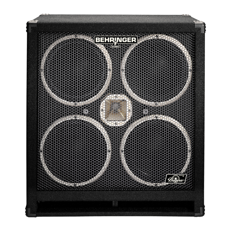
Behringer Ultrabass BVT4500H User manual

Behringer

Behringer Ultrabass BVT4500H User manual

Behringer mic500usb User manual

Behringer

Behringer mic500usb User manual

Behringer EUROPOWER EP4000 User manual

Behringer

Behringer EUROPOWER EP4000 User manual

Behringer iNuke NU12000DSP Owner's manual

Behringer

Behringer iNuke NU12000DSP Owner's manual

Behringer MicroPHONO PP400 User manual

Behringer

Behringer MicroPHONO PP400 User manual

Behringer POWERPLAY P1 User manual

Behringer

Behringer POWERPLAY P1 User manual

Behringer Powerplay Pro HA4600 User manual

Behringer

Behringer Powerplay Pro HA4600 User manual

Behringer EUROPOWER EPQ1200 User manual

Behringer

Behringer EUROPOWER EPQ1200 User manual

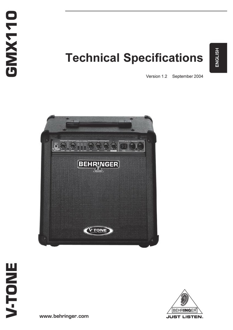
Behringer V-Tone GMX110 User manual

Behringer

Behringer V-Tone GMX110 User manual

Behringer Eurocom MA4000M User manual

Behringer

Behringer Eurocom MA4000M User manual

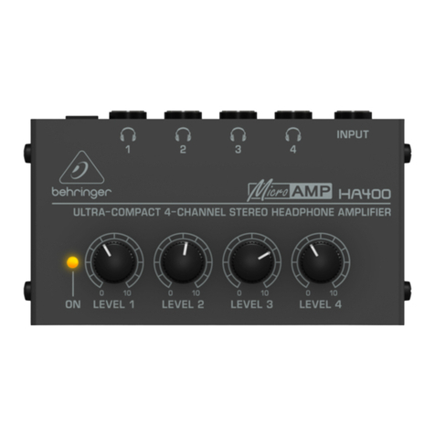
Behringer Microamp HA400 User manual

Behringer

Behringer Microamp HA400 User manual

Behringer iNuke NU6000 Installation guide

Behringer

Behringer iNuke NU6000 Installation guide

Behringer EUROPOWER EP4000 User manual

Behringer

Behringer EUROPOWER EP4000 User manual

Behringer Ultrabass BB210 User manual

Behringer

Behringer Ultrabass BB210 User manual

Behringer Ultragain Pro MIC2200 User manual

Behringer

Behringer Ultragain Pro MIC2200 User manual

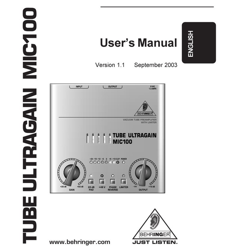
Behringer TUBE ULTRAGAIN MIC200 User manual

Behringer

Behringer TUBE ULTRAGAIN MIC200 User manual

Behringer Powerplay Pro HA4400 User manual

Behringer

Behringer Powerplay Pro HA4400 User manual

Behringer EUROPOWER PMP2000 User manual

Behringer

Behringer EUROPOWER PMP2000 User manual

Behringer EUROPOWER EP2000 User manual

Behringer

Behringer EUROPOWER EP2000 User manual

Popular Amplifier manuals by other brands

Cyrus X Power User instructions

Cyrus

Cyrus X Power User instructions

AMC MMA 120X user manual

AMC

AMC MMA 120X user manual

Goldmund MIMESIS 24 user manual

Goldmund

Goldmund MIMESIS 24 user manual

Kramer VP-200K user manual

Kramer

Kramer VP-200K user manual

HumanTechnik PL-200 operating instructions

HumanTechnik

HumanTechnik PL-200 operating instructions

University Sound 1430A Product data

University Sound

University Sound 1430A Product data

Rotel RA-971MKII owner's manual

Rotel

Rotel RA-971MKII owner's manual

Clifton LAboratories z10040b Assembly and operation manual

Clifton LAboratories

Clifton LAboratories z10040b Assembly and operation manual

Kenwood KAF-S500 instruction manual

Kenwood

Kenwood KAF-S500 instruction manual

Boss Audio Systems RGD2400 user manual

Boss Audio Systems

Boss Audio Systems RGD2400 user manual

Baudcom EDFA-1550 operating manual

Baudcom

Baudcom EDFA-1550 operating manual

Kicker PXIBT100.2 owner's manual

Kicker

Kicker PXIBT100.2 owner's manual

Marantz 1122DC Service manual

Marantz

Marantz 1122DC Service manual

Classe Audio SSP-25 owner's manual

Classe Audio

Classe Audio SSP-25 owner's manual

Yamaha CA-810 Service manual

Yamaha

Yamaha CA-810 Service manual

Nova Electronics Aquapower user manual

Nova Electronics

Nova Electronics Aquapower user manual

Crest Audio 8002 owner's manual

Crest Audio

Crest Audio 8002 owner's manual

Peavey PV 1 operating manual

Peavey

Peavey PV 1 operating manual

manuals.online logo
manuals.online logoBrands
  • About & Mission
  • Contact us
  • Privacy Policy
  • Terms and Conditions

Copyright 2025 Manuals.Online. All Rights Reserved.