BEICH CH9720 Series User manual

OPERATION MANUAL
CH9720 Series Programmable DC
Electronic Load
BEICH ELECTRONIC TECHNOLOGY CO.,LTD.

Declaration
Note:
The right of the manual is belonged to Changzhou Beich Electronic Co., Ltd, which reserves all
rights. Any printing, copy or translate can’t be done without the authorization of Beich.
The manual is available for CH 9720 Series Programmable DC Electronic Load
Any information contained in the manual is subject to change without notice
The latest version can be downloaded from our website:
http://www.beich.com.cn
June, 2017 ……………………………………..1st Edition
September, 2017………………………………..2st Edition
The descriptions contained in this manual may not cover all information about this instrument.
Introductions to the improvements of the instrument in performance, function, internal structure,
outer appearance, accessories, packing material, etc. are subject to change without notice. If you find
any inconformity of this manual with our instruments, please contact us for further consultation by
the address listed on the cover.

CH9720 Operation Manual chapter 1 Unpacking
I
Content
Content.......................................................................................................................................................... I
CHAPTER 1 UNPACKING........................................................................................... 3
1.1Unpacking...............................................................................................................................................3
1.2Power supply.......................................................................................................................................... 3
1.3 Fuse..........................................................................................................................................................3
1.4Power connection................................................................................................................................... 3
1.5 Environment.........................................................................................................................................4
1.6 Startup.................................................................................................................................................. 4
CHAPTER 2 DESCRIPTION........................................................................................ 5
2.1 Product introduction..............................................................................................................................5
2.2 Technical parameter.............................................................................................................................. 6
2.3 Front panel..............................................................................................................................................7
2.4 Rear panel...............................................................................................................................................8
2.5 Display.....................................................................................................................................................8
CHAPTER 3 MENU OPERATION.............................................................................10
3.1 Normal page......................................................................................................................................... 10
3.1.1Test operation in normal page..........................................................................................................11
Constant current mode (CC).................................................................................................................... 11
Constant voltage mode (CV)................................................................................................................... 11
Constant power mode (CP)......................................................................................................................12
Constant resistance mode (CR)................................................................................................................ 12
CC+CV mode..............................................................................................................................................13
CR+CV mode..............................................................................................................................................13
3.2 Set page................................................................................................................................................. 13
3.2.1Load Setup....................................................................................................................................... 14

CH9720 Operation Manual chapter 1 Unpacking
II
Remote test.............................................................................................................................................. 14
Auto off....................................................................................................................................................14
Current range........................................................................................................................................... 14
Max. Current............................................................................................................................................15
Voltage range........................................................................................................................................... 15
Max. Voltage............................................................................................................................................ 15
On voltage................................................................................................................................................15
Off voltage............................................................................................................................................... 16
Rise rate................................................................................................................................................... 16
Fall rate.................................................................................................................................................... 16
3.2.2 Limit Set......................................................................................................................................... 16
3.2.3 System Setup Page..........................................................................................................................17
3.2.4 File List........................................................................................................................................... 18
Save and load........................................................................................................................................... 18
Save file to U disk....................................................................................................................................19
File list..................................................................................................................................................... 20
3.2.5Battery Test Set................................................................................................................................ 21
3.2.6 Tran test (Dynamic Test).................................................................................................................22
3.2.7 List Test...........................................................................................................................................23
3.2.8LED Test.......................................................................................................................................... 25
3.2.9 System Info..................................................................................................................................... 25
3.2.10 Calibration.................................................................................................................................... 26
3.2.11 Firmware update........................................................................................................................... 26
APPENDIX AREMOTE TEST AND TRIGGER........................................................27
A1 Remote test......................................................................................................................27
A2 External trigger......................................................................................................................27
A3 Pin configuration......................................................................................................................27
APPENDIX B REMOTE CONTROL..........................................................................29
A.1 RS232C remote control system.......................................................................................................... 29
A.2 USB remote control system................................................................................................................ 30
A.3 Data format..........................................................................................................................................32

CH9720 Operation Manual Chapter 2 Description
3
Chapter 1 Unpacking
Thanks for your purchase, please inspect the packing list along with the product, if anything
missed, please contact us.
1.1Unpacking
Inspect the shipping container for damage after unpacking it. It is not recommended to power on the
instrument in the case of a damage container.
If the contents in the container do not conform to the packing list, notify us or your dealer.
Standard Accessary
QTY
Note
CH972X DC Load
1
According to order
Power plug
1
Different in different countries
Fuse
2
250V/1A,Slow-Blow
Manual
1
Test report
1
1.2Power supply
Inspect the following items:
Requirement
Voltage
220/110(1±10%)V AC
Frequency
47∼63Hz
Max. Power consumption
30VA
1.3 Fuse
Specification:250V/1A (Slow-Blow),520mm
The fuse is a standard configuration, so use the included custom fuse please.
1.4Power connection
1) Power supply: 90V to 240V (dependable on the voltage setup on the rear panel).
2) Power supply frequencies: 50Hz and 60Hz
3) Power supply power range: ≤30VA
4) L (line wire), N (neutral wire) and E (earth ground wire) of the power supply input socket
should correspond to the power plug of the instrument.
5) The instrument has been specially designed for decreasing noise jamming caused by the input
in AC power terminal, but it is also recommended to use it in the environment of low noise. If

CH9720 Operation Manual Chapter 2 Description
4
noises cannot be avoided, install a power source filter please.
WARNING: To avoid injury to personnel and damage to the instrument resulting from electric
shock, do sure that the earth ground wire is safely grounded.
1.5 Environment
1.Do not store or use the instrument where it could be exposed to many dusts, great
vibration, direct sunshine and corrosive gas.
2.The instrument should operate under the temperature ranging from 0℃to 40℃,
relative humidity of no greater than 75%. For high accuracy, use the instrument in the
environment above mentioned.
3.For high accuracy, do not block the left air vent so as to ensure good ventilation.
4.The instrument has been specially designed for decreasing noise jamming caused by
the AC power input, but it is also recommended to use it in the environment of low
noise. If noise cannot be avoided, install a power filter please.
5.If the instrument will not be used for a long time, please place it in the original or a
similar packing box. The environment temperature should be kept in the range of 5℃
to 40℃, and the relative humidity should not be greater than 85%. The box should be
located in an airy room where it could be exposed corrosive impurities and direct
sunlight.
6.Test leads on the instrument that are connected to DUTs should be kept away from
strong electromagnetic fields to avoid interference.
1.6 Startup
Press the start key on the left corner, then the power is connected, then self-inspection, load the
configuration information and initialization.
Please remove the power plug from the socket when not using for long time.

CH9720 Operation Manual Chapter 2 Description
5
Chapter 2 Description
2.1 Product introduction
CH9720X series electronic load is the new generation high performance
multi-function DC electronic load based on the professional accumulation in the field of
electronic load and wide users. The high performance ARM processor with high speed
sampling AD is adopted, so it can simulate the load feature of different power supply.
4.3 inch TFT display supports Chinese&English operation, matched with guided menu,
make the operation easier. The displayed information is rich and direct. With the
resolution of 0.0001, the voltage and current details can be monitored more
accurate.USBHOST(available for 9720BU/9720CU) can be used to save data,also for
firmware update. The comparator function with HANDLER interface can ensure the
batch test and systemization test. The load function is rich: CC, CV, CP, CR,
CR-LED(Simulate the characteristic of driver),battery discharge function(Display the
real-time discharge curve), transient test(Test the dynamic output performance of power
supply) , list test(Test the performance of the power supply under different condition).
The flexible soft and hard frame can meet the demand of group test so that to improve
the test efficiency. The smart fan control and excellent dispersion performance with the
protection alarm steps like over voltage, over current, over power, over heat and reverse
voltage polarity can make the instrument more reliable and safer. It is easier to connect
with computer for real time sampling collection and control with SCPI.
The electronic load can be widely applied for the production line of power
transformer, charger, switch power and battery, and the research field like lab.
CH9720 Operation Manual Chapter 2 Description
6
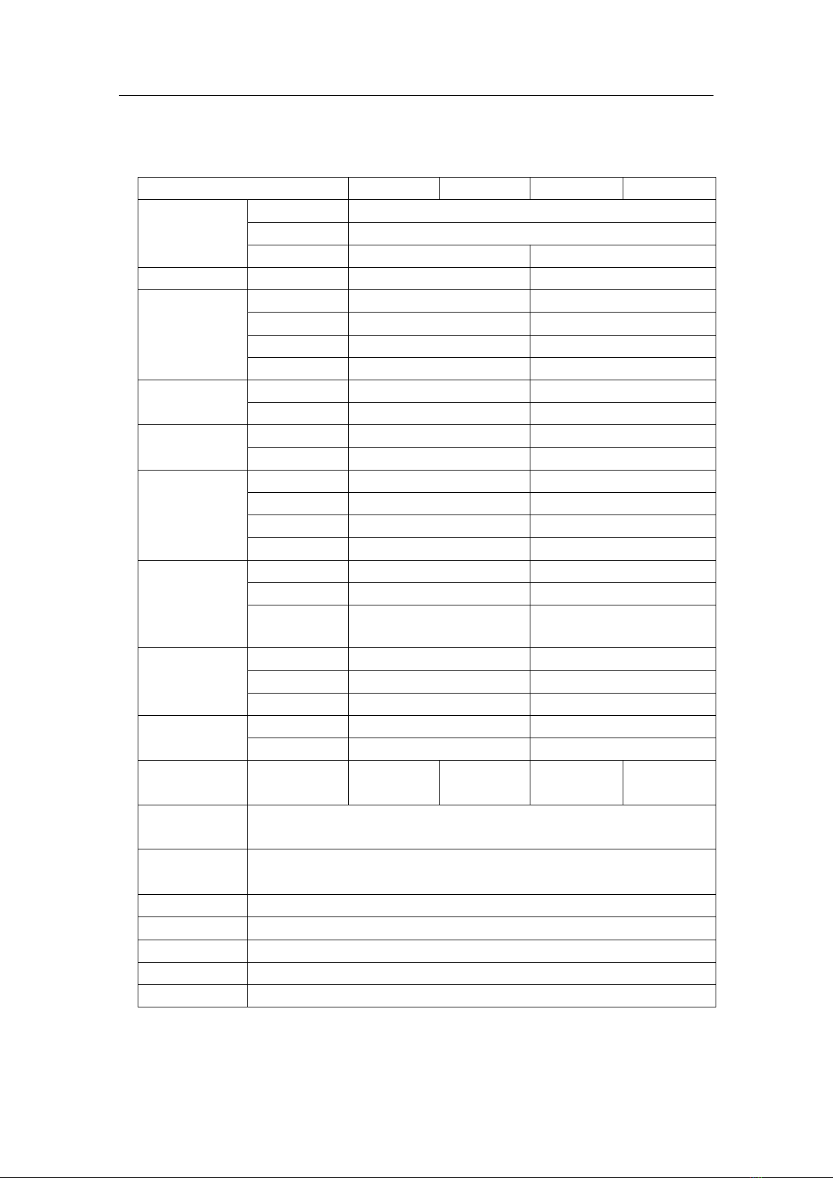
2.2 Technical parameter
Model
CH9720B
9720BU
CH9720C
CH9720CU
Rated value
Input voltage
0~360V
Input current
1mA~30A
Input power
150W
300W
Range
Accuracy
Resolution
Load accuracy
0-36V
±(0.05%+0.03%FS)
1mV
0-360V
±(0.05%+0.03%FS)
10 mV
0-3A
±(0.05%+0.05%FS)
0.1 mA
0-30A
±(0.05%+0.05%FS)
1 mA
CV mode
1.5V-36V
±(0.05%+0.03%FS)
1mV
1.5V-360V
±(0.05%+0.03%FS)
10mV
CC mode
0-3A
±(0.05%+0.05%FS)
0.1 mA
0-30A
±(0.05%+0.05%FS)
1mA
CR mode(when
input voltage
and current ≥
10%FS)
0.05Ω-5Ω
±(0.2%+0.2%FS)
0.001Ω
0.5Ω-50Ω
±(0.1%+0.1%FS)
0.01Ω
5Ω-500Ω
±(0.1%+0.1%FS)
0.1Ω
500Ω-5KΩ
±(1%+1%FS)
1Ω
CP mode(when
input voltage
and current ≥
10%FS)
0-50W
±(0.1%+0.1%FS)
1 mW
0-150W
±(0.1%+0.1%FS)
10 mW
0-300W
±(0.1%+0.1%FS)
0.1 W
Voltage test
accuracy
0-9.9999V
±(0.05%+0.03%FS)
0.1mV
10.000-99.999V
±(0.05%+0.03%FS)
1mV
100.00-360.00V
±(0.05%+0.03%FS)
10mV
Current test
accuracy
0-9.9999A
±(0.05%+0.05%FS)
0.1 mA
10.000-30.000
±(0.05%+0.05%FS)
1mA
U-disk Data
Save
Unavailable
Available
Unavailable
Available
U-disk Firmware
update
Available
Battery test
function
Input voltage= 0.8-360V Max.Capacity= 999A/H
Resolution=0.1mA Discharge time=1~
60000
sec
Transient test mode
T1&T2(Test time of value A or B):0.1mS-999S Error<2.5% + 0.1mS
Protective range
>rated condition 5%
Input impedance
≥200KΩ
Dimension
W*H*D 230mm*100mm*350mm
Weight
CH9720B/BU 6Kg CH9720C/CU 6.5Kg
-------------------------------------------------------------------------------------------------------------------------

CH9720 Operation Manual Chapter 2 Description
7
4
3
2
1
8
5
6
7
2.3 Front panel
No.
Name
Description
1
Power
Turn on and off the load.
2
USB HOST
Connect USB disk. Support FAT16 and FAT 32.Firmware
update, data storage and load, save screen imagine(Only
available for CH9720BU/9720CU)
3
Operation
ON:Start up the load test.
SAVE:Save the data to U disk, the light is blinding when data
is recording (Only available for CH9720BU/9720CU)
4
LCD display
Display test result, condition and system information.
5
Input
Full-functional numerical keyboard, used to input data, or
character for file name.
6
Knob
Right-left adjustment for setting data and menu operation
7
Input terminal :red is
positive and black is
negative
Reversed polarity input will cause big
current, dangerous
8
Soft key
The function of 5 keys is changed as function page, which is
not fixed. In different menu, there is different function. The
function is displayed on the top of the key .
CH9720 Operation Manual Chapter 2 Description
8
2
1
3
4
5
6
7
1
3
4
5
6
2
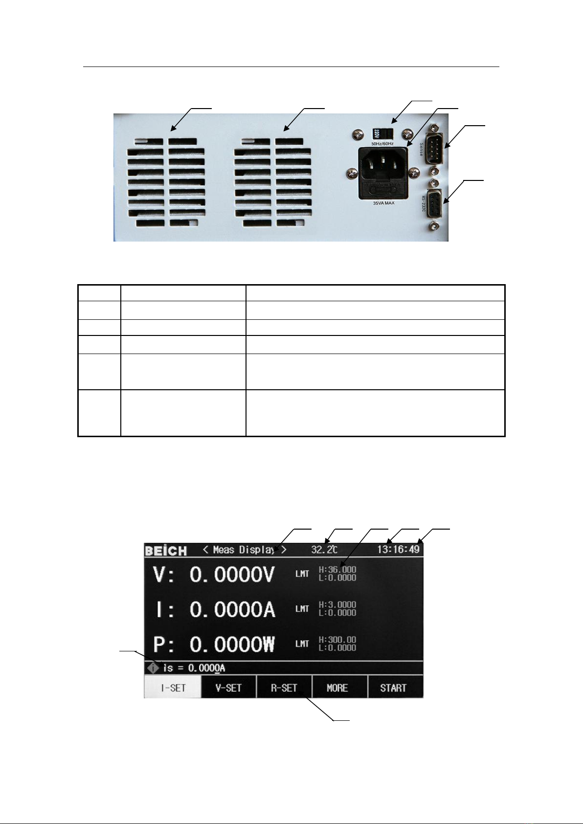
2.4 Rear panel
No.
Name
Description
1,2
Cooling hole
Please not block and keep cooling
3
Voltage switcher
Switch 110V and 220V
4
AC input
1A fuse is inside of
5
Remote test and trigger
input interface
The configuration of pin is referred to appendix A
6
RS232C interface
Communicate with external device, parameter setting and
command can be set and obtained by PC to realize remote
control.
2.5 Display
LCD display is divided into fixed zones, the information is as below.

CH9720 Operation Manual Chapter 2 Description
9
No.
Name
1
Parameter setting and
status indication
Parameter setting with load and help hints in menu setting
2
Primary parameter
Display real-time voltage, current and power
3
Internal temperature in
device
Display the monitored internal temperature
4
Limit alarm setting
value
Set the high and low limit in normal test model, alarm when
over the limit, more details in 3.2.2
5
System display
Display system information by means of icon
U disk is available;
remote control;
6
Clock display
Display real-time clock, change the date and time in system
interface or turn off the display.
7
Load mode
Select load mode
CH9720 Operation Manual Chapter 3 Menu Operation
10
Chapter 3 Menu operation
In this chapter, the menu information and operation is described in details
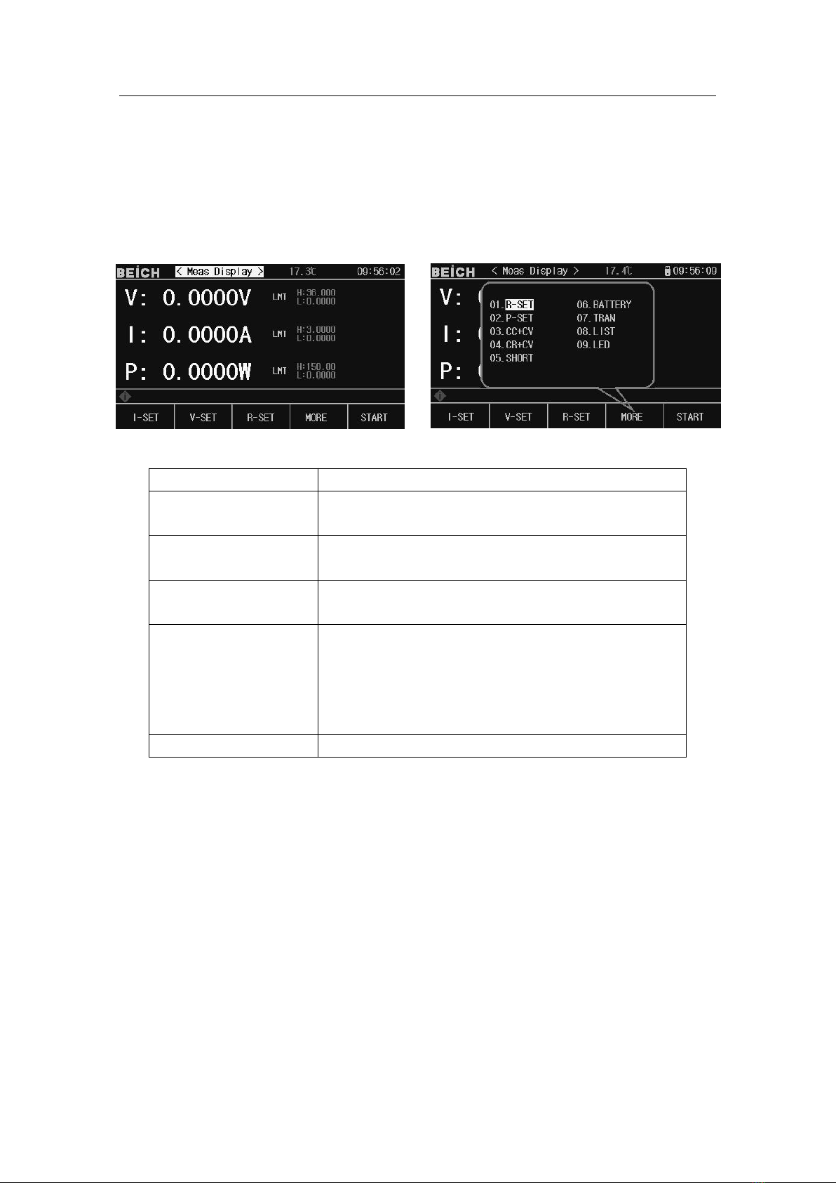
3.1 Normal page
Name
Description
Constant current CC
(Fixed)
No matter the input voltage is changed or not, the DC load
consumes a constant current
Constant voltage CV
(Fixed)
The DC Load consumes enough current to fix the input
voltage in the set value
Flexible definition key
The item is flexible, which is decided by more options in
menu
More
Press the key and there will be more optional pages,
including CR,CP,CC+CV,CR+CV,SHORT,battery
test, dynamic test, list test, LED test, scanning test, which
can be selected by cursor or input number, after selection ,it
will be displayed in the flexible definition key
Start
Turn on and off load
CH9720 Operation Manual Chapter 3 Menu Operation
11
3.1.1Test operation in normal page
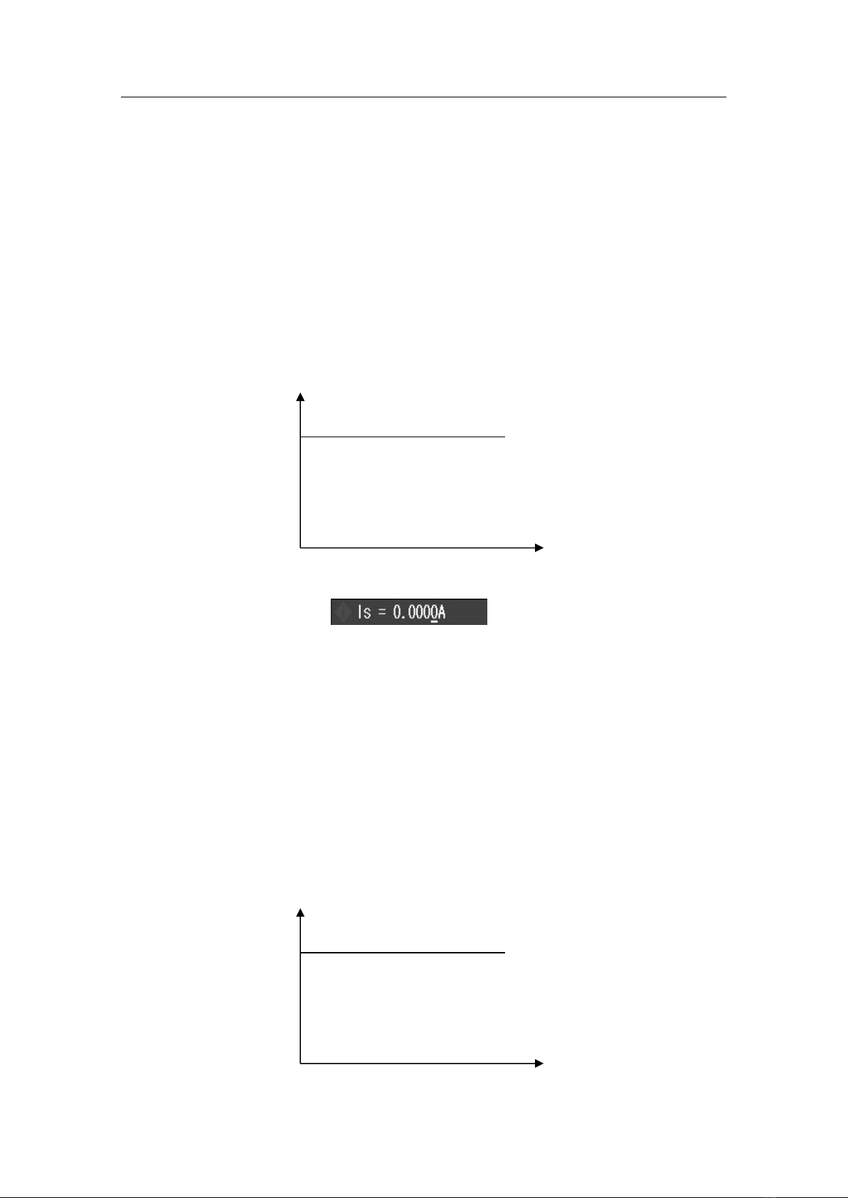
Constant current mode (CC)
No matter the input voltage is changed or not, the DC load consumes a constant current
I
(set current)
Load current
V
Input voltage
Press 【CC】to enter CC mode, the key is light, input the current value, and the number
is displayed in status bar
and press 【Ent】to confirm. Press【Start】or【ON】to start the load test.
E.g.:Set current value to 1.2345A。
In CC mode, input 1.2345,and press【Ent】to confirm
In the load startup status, use【▲】or【▼】to move cursor, or knob to change the
parameter, or use number key to reset the parameter, the load will follow up the changed
value.
Constant voltage mode (CV)
The DC Load consumes enough current to fix the input voltage in the set value
V
(set voltage)
Input voltage
I
Load current
CH9720 Operation Manual Chapter 3 Menu Operation
12
Note:Please refer to the current setting for voltage setting
Note:When the source voltage is smaller than set value, the load can’t operate CV.
Note :The difference value of source voltage and set value lands on the source and lead
resistance, then the load may consume bigger current!
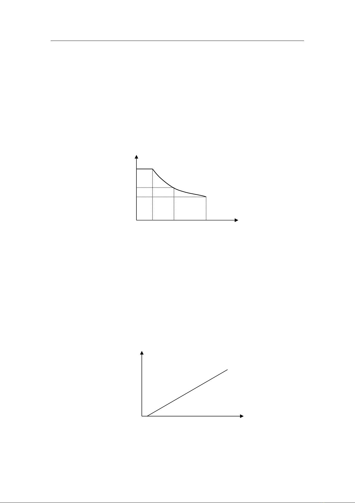
Constant power mode (CP)
In CP mode, the DC Load consumes a constant power. When the input voltage is changed, the
load adjusts current to maintain the power
V
V1
Input voltage
V2 (Set power P)
V3
I1 I2 I3 I
Load current
In other load mode, press【More】to enter menu to select power mode,and use【Start】to start
or stop working.
When the load is not started, use cursor and knob to set value, or press【CP】to use number key to
input the new value.
Note:Please refer to current setting to set the power
Constant resistance mode (CR)
In CR mode, load is equivalent as an constant resistance, load consumes the changed current as
the change of voltage
I
Slop(R set)
Load current
V
Input voltage
Note:Please refer to the current set to set resistance

CH9720 Operation Manual Chapter 3 Menu Operation
13
CC+CV mode
CC+CV mode is CC plus CV, which function is to protect tested source not to be damaged by
over charge.
Setting and test:
1. In more test mode, move cursor to CC+CV and press【ENT】to confirm,press【CC】to set current,
press【CV】to set the parameter of CV.
2. Press start to test, if DC Load judges the current can be loaded to the set value, then the DC
Load is in CC mode, if the source current can’t be output to set value, then turn to CV mode,
now the Max. Output current is displayed.
CR+CV mode
The function of CR+CV mode is same as CC+CV,please refer to the setting of CC+CV mode.
3.2 Set page
Press【SET】to enter the menu, use direction key, rotate knob to move cursor or input the front
two numbers to enter the menu.
CH9720 Operation Manual Chapter 3 Menu Operation
14
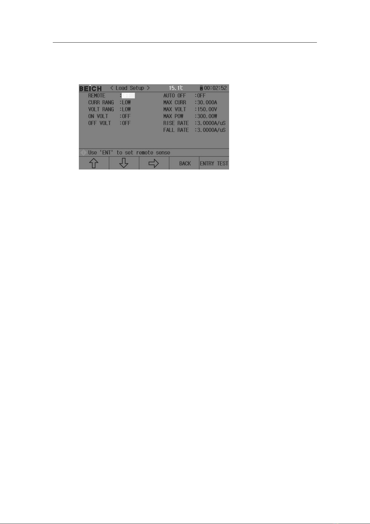
3.2.1Load Setup
Move cursor to select load, and press【ENT】or input 01 to enter
Remote test
In CV,CR,CP mode,the accuracy of voltage sampling affect the working accuracy of DC
load. When the load consumes bigger current, there is voltage drop in the connection cable
between tested sources to DC Load. In order to ensure the test accuracy, DC Load provides a
remote test terminal on the rear panel; user can use it to test the voltage from output terminal.
Use【ENT】to change the setting, press【ENT】once, and ON and OFF is switched
Voltage remote test=On:turn on the remote test, the voltage is sampled from remote test
terminal on the rear panel
Voltage remote test=Off:turn off remote test, the voltage is sampled from input terminal on
the front panel
Note:the pin configuration of Sense interface is referred to appendix A.
Auto off
Auto off can be used in CV,CC,CP,CR mode. If delay off is turned on, the load will be off
automatically after delay time in the unit of second.
Input number, and press【ENT】to confirm,0 is off
Note:unit is second(s),range1 ~99999s。
Note:if set value is 0 or closed to 0,then delay off is “Off”,which means the function
is off.
Current range
For test accuracy, load current is divided as high and low range, in the system of Max.30 A,
0-3A is low range, and 3-30 A is high range, in the system of Max.60A, 0-6A is low range and
6-60A is high range.
Use 【ENT】to switch,when switching to low range, the Max. current is adjusted to 3A
or 6A(60A system)。

CH9720 Operation Manual Chapter 3 Menu Operation
15
Note:Press【ENT】to switch range
Max. Current
There are 2 functions of Max. load current:
1. The set current value(Is=)is limited below Max. current;
2. In CV,CP,CR and short test, when the load current is over the Max.current, the device
alarms and display over current protection (OC),if the current lasts to over Max. current, the load
will be off.
Note:Input number to set Max. Current, and press【ENT】to confirm.
Voltage range
For test accuracy, the load voltage is divided to high and low range, in the system of
Max.150V, 0-18V is low range, 18-150V is high range, in the system of Max. 500V, 0-50V is
low range; 50-500V is high range.
Use【ENT】to switch,when switching to low range, the Max. voltage is adjusted to 18V or
50V(60A system).
Note:press【ENT】t o switch range.
Max. Voltage
There are 2 functions of setting the Max. Input voltage:
1. The set CV value(Vs=)is limited below the Max. Current;
2. The DC Load alarms when the input voltage is over the Max.voltage and display “Exceed
Voltage!!!”,and the load is off;
Note:Input number to set Max. Voltage, and press【ENT】to confirm.
Max. Power
It means the Max. Power that the load can consume, if the real consumption is over the value,
the device alarms and display(OP),and may cause the load is off.
Note:Input number to set Max. Power, and press【ENT】to confirm.
On voltage
The Min. Startup voltage can be used in CV, CC, CP and CR mode. If Min. Startup voltage is
turned on, after load, once the input voltage is less that it, load is on hold and display “。。。。”,
once over it, the load is started.
E.g.:If the Min. Startup voltage is set as 1.25V,select the Min. startup voltage and input
【1】【.】【2】【5】,press【Ent】to confirm,the default unit is V.

CH9720 Operation Manual Chapter 3 Menu Operation
16
Note:If the set value is 0 or closed to 0, the Min. startup voltage is “Off” which means the
function is off.
Note:In list test mode, if set the startup voltage then the self startup function, when the
device judges the input voltage is higher than the set voltage, list test is on, and off when the
list test is finished, which can realize the auto test without using keyboard .
Off voltage
The Min. off voltage can be used in CV, CC, CP and CR mode. If the auto cut-off voltage is
turned on, after load, when the input voltage is less than it then the load is off
Note:The setting is same as Min. Startup voltage.
Note:If the set value is 0 or closed to 0, the Min. startup voltage is “Off” which means the
function is off.
Rise rate
Used to set the rise speed, which to decrease the over current shock under some condition. Input
data and press【Ent】to confirm,the Max. set current is 3.000A/uS。
Fall rate
Used to set the time from the normal working to unload. Input data and press【Ent】to confirm,
the Max. set current is.000A/uS。
Note:After all setting is over, then press【ENTRY TEST】to the main test page or press
【BACK】.
3.2.2 Limit Set
On this page, the voltage, current and power parameter can be set, and display the result in the test
interface. If over the set value, then display in red.
Note:Mover cursor to the set position, input number and press【Ent】to confirm, list judge can be
set on or off by pressing【Ent】,after setting, press【ENTRY TEST】to the main test page or press
【BACK】.

CH9720 Operation Manual Chapter 3 Menu Operation
17
3.2.3 System Setup Page
On the page , the system style and application can be set,press【Ent】to switch the menu,input umber
to set date and time then press【Ent】to confirm
Menu
Secondary Menu
Theme
GRAY
CYAN
BLACK
BLUE
Trigger Source
(MAN):Triggered by“TRIG”key
(EXT):External trigger,triggered by Sense on the rear panel
(BUS):Triggered by command via RS232C interface
Language
中文
ENGLISH
Comm mode
RS232C
USB-CDC
USB-TMC
Poweron set
Default
Last
Local Addr
Input number and press【Ent】to confirm
Key sound
On
Off
Baud rate
4800 9600 19200 38400 57600
Key loack
On Lock 0-9 key when ON
Off
Multi Mode
SEPAR
MULTI
Knob Lock
On
Off
Defaul Mode
Reset Restore to factory setting after confirmation, please
be note
Acquis Freq
Used to set the sampling time for USB storage
Date
Input number key to press【Ent】to confirm,move cursor to next

CH9720 Operation Manual Chapter 3 Menu Operation
18
item
Time
Input number key to press【Ent】to confirm,move cursor to next
item
3.2.4 File List
Save and load
By this function , the parameter can be saved, and the setting can also be saved to internal ROM or
external USB storage,the test result and screen shot can be saved to external USB storage
Save
The function is as below:
Save the revised data and setting;
Save the setting parameter and system parameter;
Save the setting to internal ROM storage or external USB storage by means of file;
Save the screenshot to USB storage;
Save test result to USB storage(Data recording).
Load
After save, then realize the following load function:
Auto load the revised data and setting;
Load the setting parameter;
Load the system parameter;
Load the setting file in internal ROM storage or external USB storage;
Saved Media Type
The saved media is as:
Type
Function
Internal RAM (Powered by
Battery)
Save the test parameter and system configuration
Internal FLASH ROM
Revised data and setting, setting file
Other manuals for CH9720 Series
1
This manual suits for next models
4
Table of contents
Other BEICH Power Supply manuals


