N2Power XL270 Series User manual

PMBus Interface: User’s Guide
XL270 Series
270-Watt AC to DC
Power Supplies
706679 Rev 09-26-18

ENGINEERING DEPARTMENT
706679 Rev 09-26-18 1 of 9
User’s Guide
XL270 PMBus Interface
This document and the PMBus™firmware described within are subject to change without notice. PMBus is a
trademark of System Management Interface Forum, Inc.
The N2Power XL270 Series of power supplies optionally supports the industry standard PMBus. This document
lists the commands that are currently supported in Version 1.2 of the XL270 PMBus implementation. Refer to
the complete XL270 Product Specification (Document 706601) for details about the power supply’s operational
characteristics.
Refer to the PMBus Power System Management Protocol Specification Parts I and II
Part I: General Requirements, Transport and Electrical Interface
Part II: Command Language
The PMBus documents can be downloaded at the following URLs:
http://pmbus.org/developers.php
http://pmbus.org/media/PMBus_Specification_Part_I_Rev_1_%200_20050324.pdf
http://pmbus.org/media/PMBus_Specification_Part_II_Rev_1_0_20050328.pdf
The PMBus is a logical protocol based on the SMBus that was originally conceived by Intel Corporation. They
both utilize the 5-volt I2C hardware bus. The 3.3-volt integrated circuits of XL270 can tolerate the 5-volt I2C
Bus. Electrical and timing requirements must comply with the I2C Bus specifications. These physical
requirements are generally fulfilled by an integrated circuit. External pullup resistors on the I2C clock and data
lines are required. The XL270 I2C inputs provide weak pullups to 3.3V to keep the clock and data input signals
in their high state when not used.
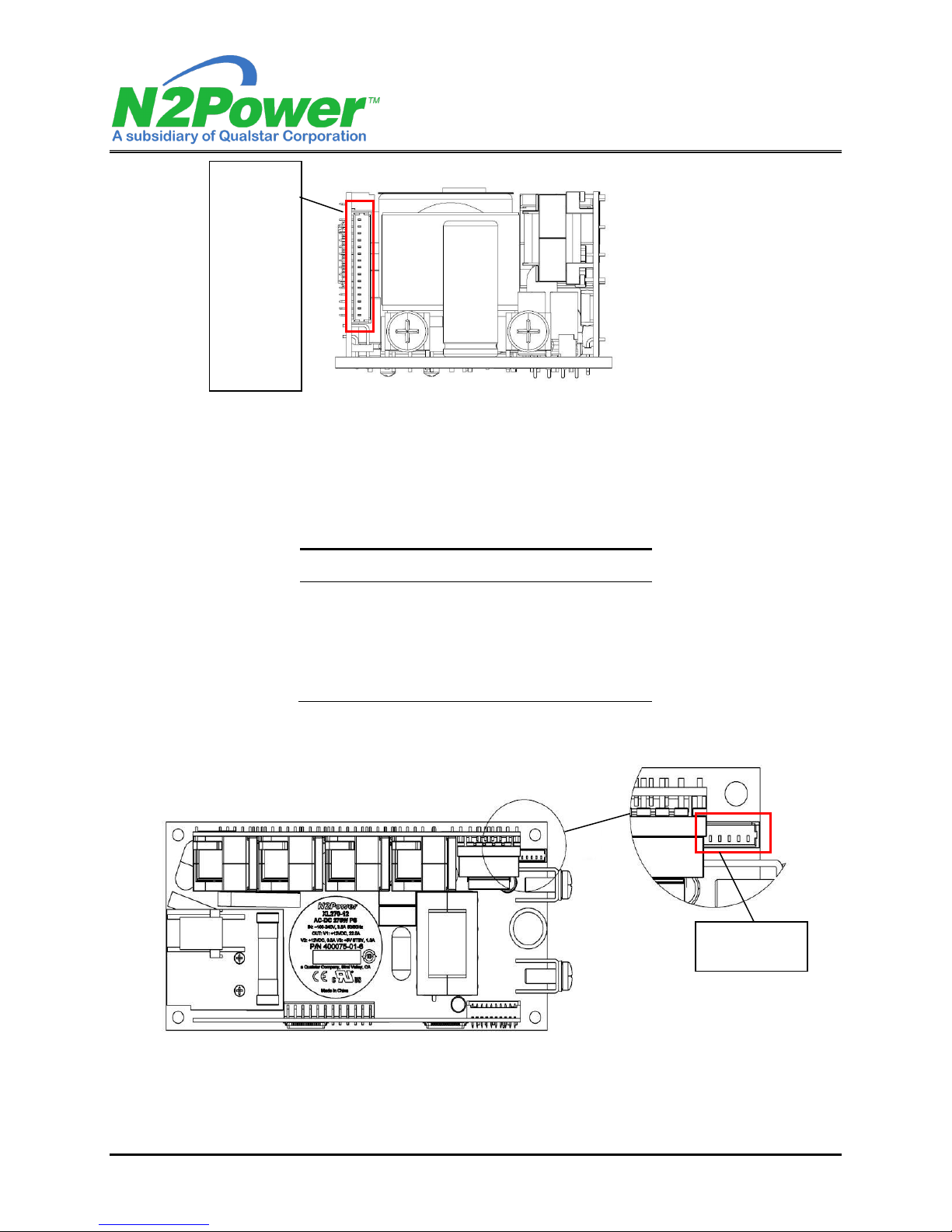
Option Connector (J3)
The J3 connector is a Molex Pico-Blade header (a.k.a. a jack) with 1.25mm pin spacing. The Molex part
numbers for the mating housing and crimp-style snap-in terminals are listed in Table 1. There may be
equivalent connector components available from other manufacturers.
J3
Molex P/N
Number of Circuits (pins)
15
Mating Housing (white)
51021-1500
Crimp Terminal
50212-8100
Rated Contact Current
2 A
Rated Wire Size
AWG 30 thru 24
Table 1 J3 Mating Connectors

ENGINEERING DEPARTMENT
706679 Rev 09-26-18 2 of 9
Figure 1 J3 Connector
Tachometer Input, Auxiliary (Fan Controlled Output)/Standby Output Connector (J6)
The J6 connector is a Molex Micro-Latch header (a.k.a. a jack) with 2mm pin spacing. The Molex part numbers
for the mating housing and crimp-style snap-in terminals are listed in Table 2. There may be equivalent
connector components available from other manufacturers.
J6
Molex P/N
Number of Circuits (pins)
5
Mating Housing (white)
51065-0500
Crimp Terminal
50212-8100
Rated Contact Current
2 A
Rated Wire Size
AWG 30 thru 24
Table 2 J6 Mating Connectors
Figure 2 J6 Connector
Pin numbers
15
14
13
.
.
.
3
2
1
J3 Connector
Pin numbers
1 2 3 4 5

ENGINEERING DEPARTMENT
706679 Rev 09-26-18 3 of 9
Signal Descriptions and Connector/Pin Assignments
Signal
Description/Remarks
I2C Serial Clock
Provides PMBus control/status interface. Pulled-up to 3.3V by a
4.7K resistor. Maximum frequency is 100Khz.
I2C Serial Data
Provides PMBus control/status interface. Pulled-up to 3.3V by a
4.7K resistor.
Address 1
High-true address selection input (2 bits: 0, 1).
Address 0
High-true address selection input (2 bits: 0, 1).
DC Return (ground)
XL270 circuit return for all outputs and status/control signals. (RTN)
CAN HIGH
HIGH data line for CAN (Controller area Network)
communications (for current sharing and service use)
CAN LOW
LOW data line for CAN (Controller area Network)
communications (for current sharing and service use)
-RS
Remote sense for RTN
+RS
Remote sense for VOUT (compensates for load-cable drop)
PF/PG
A high-logic level (≈4.5V) indicates the output power is in
regulation for at least the next 2ms.
RE
Remote Enable Input
12V Auxiliary
(12VAUX) / FAN
Controlled Output
Provides 0.5A at 12V. Uses RTN for its return.
With the PMBUS command, this output can switch on and off with
a preprogrammed duty cycle to control fan speed.
5VSB
Provides 1A at 5V. Uses RTN for its return.
Tachometer Input
The tachometer output of a single fan may be connected to this
input. The loss of the tachometer signal is detected and can be
reported over the optional serial data interface.
Table 3 Signal Descriptions and Connector/Pin Assignments

ENGINEERING DEPARTMENT
706679 Rev 09-26-18 4 of 9
Pin
Signal Name
J3-1
I2C Serial Clock
J3-2
I2C Serial Data
J3-3
Address 1 Input (A1, see below)
J3-4
Address 0 Input (A0, see below)
J3-5
DC Return (ground)
J3-6
DC Return (ground)
J3-7
CAN High (CANH) (for Current Sharing)
J3-8
CAN High (CANH) (for Current Sharing)
J3-9
CAN Low (CANL) (for Current Sharing)
J3-10
CAN Low (CANL) (for Current Sharing)
J3-11
Negative Remote Sense (-RS)
J3-12
Positive Remote Sense (+RS)
J3-13
Power Fail/Power Good (PF/PG)
J3-14
Remote Enable (ENABLE)
J3-15
Not used
Table 4 J3 Pin Assignments
Pin
Signal Name
J6-1
Tachometer Input
J6-2
5V Standby (5VSB)
J6-3
DC Return (ground)
J6-4
12V Auxiliary (12VAUX) / FAN Controlled Output
J6-5
DC Return (ground)
Table 5 J6 Pin Assignments
I2C Levels
Low State
High State
Input Voltage
<= 1.3VDC
>= 3.0VDC
Output Voltage
<= 0.5VDC @ 8mA
Open with clamp to 3.3V
Table 6 I2C Signal Levels

ENGINEERING DEPARTMENT
706679 Rev 09-26-18 5 of 9
Addressing
The XL270 supports one of four physical bus addresses. These are determined by selectively grounding the two
high-true address input lines shown in Table 4. Leaving the address pins open will be treated as logic high.
J3-3 (A1)
J3-4 (A0)
Address
Open
Open
0 0 1 0 0 1 1
Open
GND
0 0 1 0 0 1 0
GND
Open
0 0 1 0 0 0 1
GND
GND
0 0 1 0 0 0 0
Table 7 Address Selection

ENGINEERING DEPARTMENT
706679 Rev 09-26-18 6 of 9
Supported Commands
Notes:
1) When applicable, PMBus commands use the direct data format.
2) Packet Error Checking (PEC) is not supported.
3) General Call Address (0x00, Global Broadcast) is not supported.
4) All PMBus reads are a combined data format, where there is no stop condition (stop bit) between the
write data portion (PMBus command) and the read data portion. Instead, there is a repeated start
condition (start bit) before the change of direction (repeated slave address with read bit) in the transfer.
Refer to the PMBus Specification Part II for detailed descriptions of the following supported commands:
OPERATION 0x01
An OPERATION command will cause the OPERATION byte to be written if the data is valid, but the command
will only be processed if the RE (Remote Enable) signal is not at logic low at the time that the OPERATION
command is issued. Valid data values that can be written to the OPERATION byte are 0x00 and 0x80. All other
values will be discarded. A change in the state of the remote enable (RE) signal will override any previous
OPERATION command that was issued.
Data of 0x80 will enable the main and 12Vaux outputs.
Data of 0x00 will disable the main and 12Vaux outputs.
CLEAR_FAULT 0x03
Clears the status byte and status word.
STATUS_BYTE 0x78
Returns the Low byte of the Status Word. See Table 8.

ENGINEERING DEPARTMENT
706679 Rev 09-26-18 7 of 9
STATUS_WORD 0x79
Byte
Bit
Number
Status Bit
Name
Description
Low
7
BUSY
Not supported.
6
OFF
Output off has occurred.
5
VOUT_OV
Output overvoltage fault has occurred.
4
IOUT_OC
Output overcurrent fault has occurred.
3
VIN_UV
Not supported.
2
TEMPERATURE
Transformer temperature fault has occurred.
1
CML
PMBus communications fault.
0
NONE OF THE
ABOVE
Not supported.
High
7
VOUT
Output voltage fault or warning has
occurred.
6
IOUT/POUT
Output current fault or warning has
occurred.
5
INPUT
Not supported.
4
MFR
Not supported.
3
POWER_GOOD
The POWER_GOOD negation has occurred.
2
FANS
Not supported.
1
OTHER
Not supported.
0
UNKNOWN
Not supported.
Table 8 Status Byte/Word Description
READ_VOUT 0x8B
The A/D count is linear from zero to 120% of nominal output voltage resulting in a full scale count of 1023d
(this equates to 0.1173% per count). Nominal output voltage (100% of rated voltage) yields a reading of 852d.
Nominal voltages are model dependent but are rated at: 12V, 24V, 30V, 48V or 56V.
The coefficient parameters used to translate the data to the actual percentage value of rated output voltage
information are given below.
Parameter
Value
m
8525d
b
0
R
-3d
Table 9 PMBus direct format coefficient parameters for READ_VOUT

ENGINEERING DEPARTMENT
706679 Rev 09-26-18 8 of 9
READ_IOUT 0x8C
The A/D count is linear from zero to 125% of nominal output current resulting in a full scale count of 1023d.
Rated output current occurs at a count of 818d. 100% of rated currents are equal to 270-watts divided by the
above output voltages. The coefficient parameters used to translate the data to the actual percentage value of
rated output current information are given below.
Parameter
Value
m
8184d
b
0
R
-3d
Table 10 PMBus direct format coefficient parameters for READ_IOUT
READ_TEMPERATURE_1 0x8D
Returns a 10-bit unsigned integer of the temperature near main transformer. The sensor measurement range is
from -40 °C to 125 °C. The XL270 will shut down when the temperature reaches around 110 °C (data value of
930d). The parameters used to translate the data to the actual temperature information are given below.
Parameter
Value
m
620d
b
24800d
R
-2d
Table 11 PMBus direct format coefficient parameters for READ_TEMPERATURE_1
MFR_SPECIFIC_01 0xD1 –Fan Speed Control, Read/Write Byte
Note: During non-default mode, internal thermostat control will override other modes and turn the fan
on at 100% duty cycle if the transformer temperature is above 85 °C.
Data Byte
Fan Speed Control Mode
0x00
100% duty cycle (power-on default mode)
0x01
Fixed speed at 0% PWM duty cycle (off)
0x02
Fixed speed at 25% PWM duty cycle
0x03
Fixed speed at 50% PWM duty cycle
0x04
Fixed speed at 75% PWM duty cycle
0x05
Fixed speed at 100% PWM duty cycle (on)
0x06
Internal automatic PWM control:
transformer Temp Duty Cycle
Above 74°C 100% duty cycle (on)
61°C-73°C 75% duty cycle
48°C-60°C 50% duty cycle
35°C-47°C 25% duty cycle
Below 35°C 0% duty cycle (off)
Table 12 Fan Speed Control Data Byte Usage

ENGINEERING DEPARTMENT
706679 Rev 09-26-18 9 of 9
MFR_SPECIFIC_02 0xD2 –Fan Tachometer Count, Read Word
This command returns a word value (low byte first) of the fan tachometer pulse count per second. The user
should know what the pulse per revolution specification is for the fan that is installed, in order to translate this
value into an actual RPM value.
If the tachometer signal is interrupted by pulse-width modulating the fan power, then the returned tachometer
pulse count per second value is only valid when the fan is powered at 100% duty cycle (continuous power). A
fan with an open collector tachometer output may still fail to provide a low output when the fan input power is
off. A four-terminal fan with a separate power and PWM inputs might provide an accurate tachometer signal at
any speed.
The coefficient parameters used to translate the data to the actual pulse count per second information are given
below.
Parameter
Value
m
1d
b
0
R
0
Table 13 PMBus direct format coefficient parameters for MFR_SPECIFIC_02
Table of contents