BEIER-Electronic AKL-8-W User manual

EN Terminal Clamp AKL-8-W
RC-Junky English Conversion 1
Operation Manual
Terminal Clamp
AKL-8-W
BEIER-Electronic
Winterbacher Str. 52/4, 73614 Schorndorf-Weiler
Telephone +49/71 1/46232, Fax 071 1/45732
eMail: modellbau@beier-electronic.de
Internet: http://www.beier-electronic.de/modellbau

EN Terminal Clamp AKL-8-W
RC-Junky English Conversion 2
Function
The AKL- -W terminal clamp was specially designed for the modules of the SFR (sound
speed controller) and UFR (speed controller) series to allow an easy connection of
LEDs, relays, smoke generators and other consumers to the switching outputs.
As a special feature, the AKL- -W terminal has eight slots for series resistors to simplify
the connection for LEDs.
Included in the delivery of the AKL- -W are eight resistors each with the values:
0 Ohms (only 1 Black ring),
150 Ohms (Brown, Green, Brown)
330 Ohms (Oran e, Oran e, Brown)
6 0 Ohms (Blue, Gray, Brown).
The negative switching outputs 1 - or 9 – 16 of SFR and UFR modules can be
connected directly via the spring-loaded terminals of the clamp. The common positive
pole is located at terminal 9 and 10. The positive pole is supplied from the internal
positive pole of the supply voltage (battery +) connection.
For example, at the SFR-1 the terminal clamp can be plugged into the slots X3 or X4.
At the UFR-1230, the terminal clamp is plugged into X5. The outer brown cable must
point to the center of the board, and the black to the edge of the board.
The terminal can now be used for an easy wiring of the model lighting.
Technical specifications
Connection terminals:
Sound speed controller SFR series:
Terminal 1 to : switching outputs 1 - or 9 - 16
of the sound speed controller (minus - switching)
Terminal 9 to 10: positive + pole of the supply
terminal
UFR speed controller series:
Terminal 1 to : switching outputs 1 - of the
Speed controller (minus - switching)
Terminal 9 to 10: positive + pole of the supply
tension
Connection cable:
10-pin Ribbon cable, 20cm long, directly pluggable
to the SFR and UFR modules
Dimension:
3 x 36 x 17 mm
Wei ht:
1 g
EN Terminal Clamp AKL-8-W
RC-Junky English Conversion 3
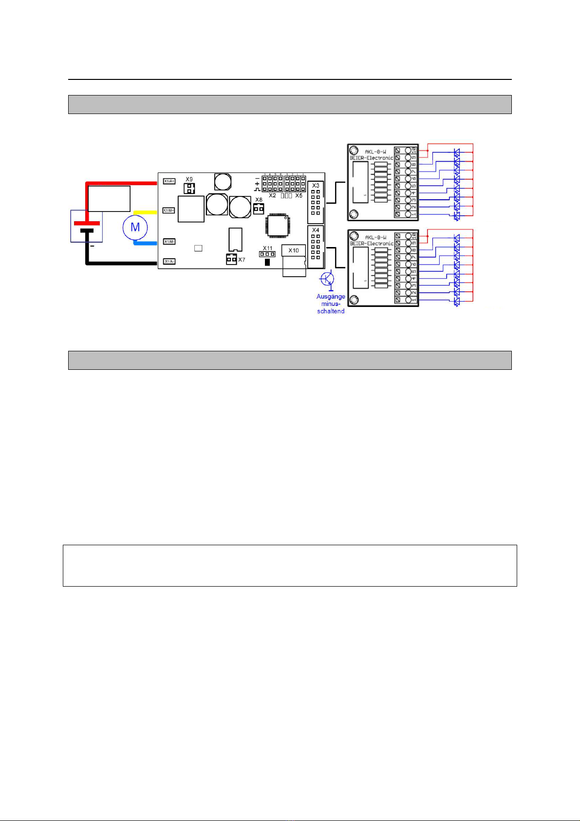
Connection example to sound speed controller SFR-1
Connection of LEDs and other components
The connection cables of the consumer/component/light can be connected to the
spring-loaded terminals of the AKL- -W. To insert or remove a cable, just press from
above with a small screwdriver on the operating lever of the terminal. This opens the
clamp and the cable can be plugged in or out.
The cables should be stripped approx. 7 - mm and be tinned with solder. The cable
cross-section can be between 0.14 mm² and 1.0 mm².
The switching outputs of the SFR and UFR are negative switching, i.e. the negative lead
of the consumer is always connected to the outputs 1- of the terminal clamp.
The positive lead of the consumer to output 9 or 10 of the terminal clamp.
The switched voltage at the eight outputs is always as high as the SFR or UFR supply
voltage! Therefore, it is important to have the correct in series resistors inserted
in the base of the AKL- -W (see below)!
Input
6
-
18V
Output 8
Output 7
Output 6
Output 5
Output 4
Output 3
Output 2
Output 1
Output 16
Output 15
Output 14
Output 13
Output 12
Output 11
Output 10
Output 9
EN Terminal Clamp AKL-8-W
RC-Junky English Conversion 4
The required value of the series resistor depends on 3 different factors:
• Level of the supply voltage (UB)
• Voltage of the LED (UL). Added together when connecting several LEDs in series
the individual stresses.
• Current of the LED (I)
The series resistance value (R) can be calculated using the following formula:
UB - UL
R = ---------- UL = (UL1 + UL2 + UL3 + ULn )
I
Example:
We have a supply voltage of 7.2 V and want a white LED with a supply voltage
3.4 V and 12 mA (= 0.012 A).
7.2 V - 3.4 V
R = ----------------- = 317 Ohms
0.012 A
However, since there is no resistance value of 317 Ohms available, we take the
closest available value of 330 Ohms.
Then the necessary power (P) of the resistor should also be checked:
P = (UB - UL) x I
P = (7.2 V - 3.4 V) x 0.012 A = 0.046 W
In this example, a standard resistor with a power of
0.250 W (1/4 W).
When connecting relays or other inductive loads (e.g. motors) free-wheeling diodes
(e.g. 1N4007) must be used.
The free-wheeling diodes must be connected in blocking direction parallel to the
consumer.
The enclosed 0 Ohm "resistors" can be used as a bridge if no in series resistor is
required at any output.
Table of contents


