Beisler 1265-7 User manual

1265-7
Operating Instructions

All rights reserved.
Property of Dürkopp Adler GmbH and protected by copyright. Any reuse of these contents,
including extracts, is prohibited without the prior written approval of Dürkopp Adler GmbH.
Copyright © Dürkopp Adler GmbH 2023
IMPORTANT
READ CAREFULLY BEFORE USE
KEEP FOR FUTURE REFERENCE

Table of Contents
Operating Instructions 1265-7 - 01.0 - 07/2023 1
1 About these instructions......................................................... 5
1.1 For whom are these instructions intended?............................... 5
1.2 Representation conventions – symbols and characters ............ 6
1.3 Other documents ....................................................................... 7
1.4 Liability....................................................................................... 8
2 Safety ........................................................................................ 9
2.1 Basic safety instructions ............................................................ 9
2.2 Signal words and symbols used in warnings ........................... 10
3 Machine description .............................................................. 13
3.1 Components of the machine.................................................... 13
3.2 Proper use ............................................................................... 13
3.3 Declaration of Conformity ........................................................ 14
4 Operation................................................................................ 15
4.1 Preparing the machine for operation........................................ 15
4.2 Switching on and off the machine............................................ 15
4.3 Operating the machine head.................................................... 16
4.4 Threading diagram................................................................... 17
4.4.1 Disconnecting the compressed air supply ............................... 18
4.5 Disassembling and assembling the fabric sliding plate............ 20
4.6 Edge guide............................................................................... 22
4.6.1 Mechanical edge guide............................................................ 22
4.6.2 Pneumatic edge guide (optional) ............................................. 23
4.7 Contour guide .......................................................................... 24
4.7.1 Adjusting the contour guide ..................................................... 25
4.7.2 Adjusting the help roller ........................................................... 26
4.8 Differential feed........................................................................ 27
4.8.1 Fullness distribution controlled by the stepper motor............... 27
4.9 Operating the fusing station..................................................... 33
4.9.1 Inserting/changing the tape ..................................................... 33
4.9.2 Switching on the fusing station ................................................ 35
4.9.3 Adjusting the temperature........................................................ 35
4.9.4 Fusing knee lining and front trousers....................................... 36
4.9.5 Adjusting the tape feed ............................................................ 38
4.9.6 Cleaning the stamp.................................................................. 39
4.10 Light barrier.............................................................................. 40
4.10.1 Aligning the light barrier ........................................................... 40
4.10.2 Adjusting the light barrier intensity........................................... 41
4.11 Stacker..................................................................................... 42
4.11.1 Operating the flip stacker......................................................... 42
4.11.2 Operating the clamping stacker ............................................... 43
4.11.3 Operating the alternating stacker............................................. 44
4.12 Air nozzles ............................................................................... 45
4.12.1 Adjusting the air nozzles in the tabletop .................................. 45
4.12.2 Adjusting the air supply............................................................ 46
4.12.3 Adjusting the air supply intensity.............................................. 46
4.13 Transport station...................................................................... 48
4.13.1 Adjusting the puller .................................................................. 49
4.13.2 Operating the puller ................................................................. 50
4.13.3 Operating the roll-out device.................................................... 50
4.14 Sewing ..................................................................................... 50

Table of Contents
2Operating Instructions 1265-7 - 01.0 - 07/2023
5 STEHA programming............................................................. 55
5.1 STEHA control panel ............................................................... 55
5.1.1 Starting up the screen.............................................................. 57
5.2 Navigating the control panel .................................................... 57
5.3 Calling up programs................................................................. 57
5.4 Main screen ............................................................................. 59
5.4.1 Setting seam-specific parameters............................................ 60
5.5 Functions of access level 2...................................................... 68
5.5.1 Setting the global parameters.................................................. 69
5.5.2 Seam sequences ..................................................................... 72
5.5.3 Pre-seams................................................................................ 74
5.5.4 Seam start mode...................................................................... 76
5.5.5 Activating the sewing motor..................................................... 76
5.5.6 Resetting the daily piece counter............................................. 76
5.5.7 Input-Output Test..................................................................... 76
5.6 Manual sewing......................................................................... 79
5.7 Machine parameters ................................................................ 80
5.8 Stacking ................................................................................... 80
5.9 Threading mode....................................................................... 81
5.10 Programming menus................................................................ 81
5.10.1 Navigating the programming levels.......................................... 82
5.10.2 Allocating a free storage location............................................. 82
5.10.3 INIT Parameters....................................................................... 82
5.10.4 Memory card............................................................................ 84
5.10.5 Diagnostics .............................................................................. 87
5.10.6 Additional programs................................................................. 90
6 Maintenance ........................................................................... 93
6.1 Cleaning................................................................................... 94
6.2 Lubricating ............................................................................... 96
6.2.1 Checking the lubrication of the machine head......................... 97
6.3 Servicing the pneumatic system .............................................. 97
6.3.1 Adjusting the operating pressure ............................................. 97
6.3.2 Draining the water condensation ............................................. 98
6.3.3 Cleaning the filter element ....................................................... 99
6.4 Parts list ................................................................................. 100
7 Setup..................................................................................... 101
7.1 Checking the scope of delivery.............................................. 101
7.2 Removing the transport locks ................................................ 101
7.3 Adjusting the working height.................................................. 102
7.4 Assembling the reel stand...................................................... 104
7.5 Assembling the flip stacker (optional) .................................... 105
7.6 Assembling the alternating stacker (optional)........................ 106
7.6.1 Assembling the delivery table ................................................ 109
7.7 Assembling the clamping stacker tray extension (optional)... 110
7.8 Electrical connection.............................................................. 111
7.9 Pneumatic connection............................................................ 112
7.9.1 Assembling the compressed air maintenance unit ................ 112
7.9.2 Adjusting the operating pressure ........................................... 112
7.10 Performing a test run ............................................................. 113

Table of Contents
Operating Instructions 1265-7 - 01.0 - 07/2023 3
8 Decommissioning................................................................ 115
9 Disposal................................................................................ 117
10 Troubleshooting................................................................... 119
10.1 Customer Service .................................................................. 119
10.2 Errors in sewing process........................................................ 120
11 Technical data ...................................................................... 123
11.1 Requirements for fault-free operation .................................... 123
11.2 Recommended threads.......................................................... 124

Table of Contents
4Operating Instructions 1265-7 - 01.0 - 07/2023

About these instructions
Operating Instructions 1265-7 - 01.0 - 07/2023 5
1 About these instructions
These instructions have been prepared with utmost care. They contain in-
formation and notes intended to ensure long-term and reliable operation.
Should you notice any discrepancies or if you have improvement requests,
then we would be glad to receive your feedback through Customer
Service (p. 119).
Consider the instructions as part of the product and store them in a place
where they are readily available.
1.1 For whom are these instructions intended?
These instructions are intended for:
• Operators:
This group is familiar with the machine and has access to
the instructions. Specifically, chapter Operation (p. 15) is
important for the operators.
• Specialists:
This group has the appropriate technical training for performing
maintenance or repairing malfunctions. Specifically, the chapter
Setup (p. 101) is important for specialists.
Service Instructions are supplied separately.
With regard to minimum qualification and other requirements to be met
by personnel, please also follow the chapter Safety (p. 9).

About these instructions
6Operating Instructions 1265-7 - 01.0 - 07/2023
1.2 Representation conventions – symbols and characters
Various information in these instructions are represented or highlighted by
the following characters in order to facilitate easy and quick understanding:
Proper setting
Specifies proper setting.
Disturbances
Specifies the disturbances that can occur from an incorrect setting.
Cover
Specifies which covers must be disassembled in order to access the
components to be set.
Steps to be performed when operating the machine (sewing and
equipping)
Steps to be performed for service, maintenance, and installation
Steps to be performed via the software control panel
The individual steps are numbered:
First step
Second step
The steps must always be followed in the specified order.
Lists are marked by bullet points.
Result of performing an operation
Change on the machine or on the display/control panel.
Important
Special attention must be paid to this point when performing a step.
Information
Additional information, e.g. on alternative operating options.
Order
Specifies the work to be performed before or after a setting.
References
Reference to another section in these instructions.
1.
2.
…
•

About these instructions
Operating Instructions 1265-7 - 01.0 - 07/2023 7
Safety Important warnings for the user of the machine are specifically marked.
Since safety is of particular importance, hazard symbols, levels of
danger and their signal words are described separately in the chapter
Safety (p. 9).
Location
information
If no other clear location information is used in a figure, indications of right
or left are always from the user's point of view.
1.3 Other documents
The machine includes components from other manufacturers. Each man-
ufacturer has performed a hazard assessment for these purchased parts
and confirmed their design compliance with applicable European and na-
tional regulations. The proper use of the built-in components is described
in the corresponding manufacturer's instructions.

About these instructions
8Operating Instructions 1265-7 - 01.0 - 07/2023
1.4 Liability
All information and notes in these instructions have been compiled in
accordance with the latest technology and the applicable standards and
regulations.
Dürkopp Adler cannot be held liable for any damage resulting from:
• Breakage and transport damages
• Failure to observe these instructions
• Improper use
• Unauthorized modifications to the machine
• Use of untrained personnel
• Use of unapproved parts
Transport
Dürkopp Adler cannot be held liable for breakage and transport damages.
Inspect the delivery immediately upon receiving it. Report any damage
to the last transport manager. This also applies if the packaging is not
damaged.
Leave machines, equipment and packaging material in the condition in
which they were found when the damage was discovered. This will ensure
any claims against the transport company.
Report all other complaints to Dürkopp Adler immediately after receiving
the product.

Safety
Operating Instructions 1265-7 - 01.0 - 07/2023 9
2 Safety
This chapter contains basic information for your safety. Read the
instructions carefully before setting up or operating the machine. Be sure
to follow the information in the safety instructions. Failure to do so can
result in serious injury and property damage.
2.1 Basic safety instructions
The machine may only be used as described in these instructions.
The instructions should be available at the machine's location at all times.
Work on live components and equipment is prohibited. Exceptions are
defined in the DIN VDE 0105.
For the following work, switch off the machine at the main switch or
disconnect the power plug:
• Replacing the needle or other sewing tools
• Leaving the workstation
• Performing maintenance work and repairs
• Threading
Missing or faulty parts could impair safety and damage the machine.
Only use original parts from the manufacturer.
Transport Use a lifting carriage or stacker to transport the machine. Raise the machine
max. 20 mm and secure it to prevent it from slipping off.
Setup The connecting cable must have a power plug approved in the relevant
country. The power plug may only be assembled to the power cable by
qualified specialists.
Obligations
of the operator
Follow the country-specific safety and accident prevention regulations and
the legal regulations concerning industrial safety and the protection of the
environment.
All the warnings and safety signs on the machine must always be in legible
condition. Do not remove!
Missing or damaged warnings and safety signs must be replaced
immediately.
Requirements
to be met by
the personnel
Only qualified specialists may be used for:
• Setting up the machine/putting the machine into operation
• Performing maintenance work and repairs
• Performing work on electrical equipment
Only authorized persons may work on the machine and must first have
understood these instructions.

Safety
10 Operating Instructions 1265-7 - 01.0 - 07/2023
Operation Check the machine during operating for any externally visible damage.
Stop working if you notice any changes to the machine. Report any chang-
es to your supervisor. Do not use a damaged machine any further.
Safety
equipment
Safety equipment should not be disassembled or deactivated. If it is essen-
tial to disassemble or deactivate safety equipment for a repair operation, it
must be assembled and put back into operation immediately afterward.
2.2 Signal words and symbols used in warnings
Warnings in the text are distinguished by color bars. The color scheme is
based on the severity of the danger. Signal words indicate the severity of
the danger.
Signal words Signal words and the hazard they describe:
Symbols The following symbols indicate the type of danger to personnel:
Signal word Meaning
DANGER (with hazard symbol)
If ignored, fatal or serious injury will result
WARNING (with hazard symbol)
If ignored, fatal or serious injury can result
CAUTION (with hazard symbol)
If ignored, moderate or minor injury can result
CAUTION (with hazard symbol)
If ignored, environmental damage can result
NOTICE (without hazard symbol)
If ignored, property damage can result
Icon Type of danger
General
Electric shock

Safety
Operating Instructions 1265-7 - 01.0 - 07/2023 11
Examples Examples of the layout of warnings in the text:
This is what a warning looks like for a hazard that will result in serious
injury or even death if ignored.
This is what a warning looks like for a hazard that could result in
serious or even fatal injury if ignored.
This is what a warning looks like for a hazard that could result in
moderate or minor injury if the warning is ignored.
Puncture
Crushing
Environmental damage
Icon Type of danger
DANGER
Type and source of danger!
Consequences of non-compliance.
Measures for avoiding the danger.
WARNING
Type and source of danger!
Consequences of non-compliance.
Measures for avoiding the danger.
CAUTION
Type and source of danger!
Consequences of non-compliance.
Measures for avoiding the danger.

Safety
12 Operating Instructions 1265-7 - 01.0 - 07/2023
This is what a warning looks like for a hazard that could result in
environmental damage if ignored.
This is what a warning looks like for a hazard that could result in
property damage if ignored.
CAUTION
Type and source of danger!
Consequences of non-compliance.
Measures for avoiding the danger.
NOTICE
Type and source of danger!
Consequences of non-compliance.
Measures for avoiding the danger.
Machine description
Operating Instructions 1265-7 - 01.0 - 07/2023 13
3 Machine description
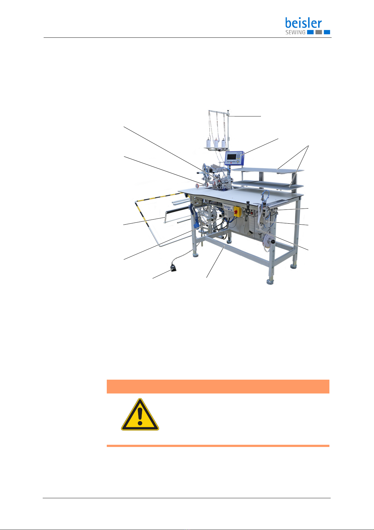
3.1 Components of the machine
Fig. 1: Components of the machine
3.2 Proper use
(1) - Machine head
(2) - Outfeed roller
(3) - Stacker
(4) - Control
(5) - Foot button
(6) - Stand
(7) - Dirt suction container
(8) - Fusing station for knee lining (optional)
(9) - Clamp for knee lining (optional)
(10) - Sewing material surface
(11) - Control panel
(12) - Reel stand
WARNING
Risk of injury from live, moving and cutting
parts as well as from sharp parts!
Improper use can result in electric shock, crushing,
cutting and punctures.
Follow all instructions provided.
⑥
⑦
⑧
⑨
①
③
④
②
⑫
⑪⑩
⑤

Machine description
14 Operating Instructions 1265-7 - 01.0 - 07/2023
The machine may only be used with sewing material that satisfies the
requirements of the specific application at hand.
The machine is intended only for use with dry sewing material. The sewing
material must not contain any hard objects.
The needle thicknesses permissible for the machine are listed in the
Technical data (S. 123) chapter.
The seam must be completed with a thread that satisfies the requirements
of the specific application at hand.
The machine is intended for industrial use.
The machine may only be set up and operated in dry conditions on well-
maintained premises. If the machine is operated on premises that are not
dry and well-maintained, then further measures may be required which
must be compatible with DIN EN 60204-31.
Only authorized persons may work on the machine.
Dürkopp Adler cannot be held liable for damages resulting from improper
use.
3.3 Declaration of Conformity
The machine complies with European regulations ensuring health, safety,
and environmental protection as specified in the declaration of conformity
or in the declaration of incorporation.
NOTICE
Non-observance will lead to property damage!
Improper use can result in material damage at the machine.
Follow all instructions provided.
Operation
Operating Instructions 1265-7 - 01.0 - 07/2023 15
4 Operation
The operating sequence consists of several different steps. Fault-free
operation is necessary in order to achieve a good sewing result.
4.1 Preparing the machine for operation
Complete the following steps in preparation of sewing before starting to
work:
• Inserting or changing the needle
• Threading the needle thread
• Threading the hook thread
• Adjusting the thread tension
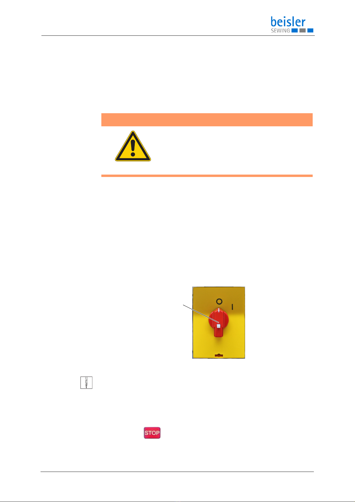
4.2 Switching on and off the machine
Fig. 2: Switching on and off the machine
To switch the machine on and off:
1. Turn the main switch (1) to the Iposition.
The machine starts up.
The control and the control panel of the machine start up.
The following appears on the control panel: WAITING FOR RESET
2. Press the button.
The following appears on the control panel: RESET
WARNING
Risk of injury from moving, cutting and sharp
parts!
Crushing, cutting and punctures are possible.
If possible, make preparations only when the
machine is switched off.
(1) - Main switch
①
Operation
16 Operating Instructions 1265-7 - 01.0 - 07/2023
3. Press the button.
The machine performs a reference run and is afterwards ready for
sewing.
4. Turn the main switch (1) to the Oposition.
The machine switches off.
4.3 Operating the machine head
Information
The operation of the machine head (needle insertion or change, threading
of needle thread and hook thread etc.) is described in the separately
included Pegasus Operating Instructions.
The Pegasus Operating Instructions are included in the accessories of
the machine.
WARNING
Risk of injury from sharp and moving parts!
Puncture or crushing possible.
If possible, operate the machine head only when
the machine is switched off.

Operation
Operating Instructions 1265-7 - 01.0 - 07/2023 17
4.4 Threading diagram
To access the threading diagram in the machine head:
1. Activate threading mode (p. 81) on the control panel.
The machine is in threading mode.
2. Remove the fabric sliding plate (p. 20).
3. Pull down the suction hose (5) to remove it.
Fig. 3: Threading diagram (2)
Disturbance
You will not be able to open the cover (7) if the pneumatic edge guide is
in its initial position (4). You can briefly disconnect the compressed air
supply (p. 18) to manually move the edge guide (8) towards the sewing
foot.
4. Slide the cover (7) to the right (6).
5. The cover (7) opens towards the bottom.
(2) - Edge guide in initial position
(3) - Suction hose
(4) - Slide to the right
(5) - Cover
⑤
④
⑥
⑦

Operation
18 Operating Instructions 1265-7 - 01.0 - 07/2023
Fig. 4: Threading diagram (3)
6. The threading diagram (9) for the machine head is shown on the inside
of the cover (7).
The types of stitches are grouped by colors.
To restore the machine head to sewing readiness after
threading is complete:
1. Fold up the cover (7).
The cover latches into place.
2. Place the suction hose (5).
3. Place the fabric sliding plate (p. 20).
4. Connect the compressed air supply (p. 18).
4.4.1 Disconnecting the compressed air supply
Fig. 5: Disconnecting the compressed air supply
To disconnect the compressed air supply:
(6) - Edge guide (7) - Threading diagram
⑨
⑧
(1) - blue ring
(2) - in arrow direction
(3) - in arrow direction
②③
①
Table of contents
Other Beisler Industrial Equipment manuals


Popular Industrial Equipment manuals by other brands


Dixon
Dixon 200-PV-9 Maintenance & Operating Intructions

Afag
Afag aflex150 qc quick guide

Danfoss
Danfoss PLUS+1 Compliant user manual

Endress+Hauser
Endress+Hauser Flexdip CYA112 operating instructions

Masterbuilt
Masterbuilt HITCH-HAUL HDMF Operation manual & safety instructions

RINGSPANN
RINGSPANN FHD 1000 Installation and operation instruction