ABB Power2 845-M46 User manual

ABB Turbocharging
Operation Manual
Power2 845-M46
HT593766_A English
Original Operation Manual
Chapter Document-ID
1 Introduction HZTL4004_EN_D
2 Safety HZTL4025_EN_B
3 Safety data sheets HT593766_A
4 Product description HZTL4070_EN_C
4.1 Low-pressure stage PT002831 HZTL4068_EN_A
PT002832 HZTL4068_EN_A
4.2 High-pressure stage PT002829 HZTL4069_EN_B
PT002830 HZTL4069_EN_B

Operating limits and replacement intervals
The recommended replacement intervals and the corresponding operating limits in chapter 3 are jointly defined
with the enginebuilder. This information is specific to the product.
Non-observance of the recommended replacement intervals and the operating limits increases the risk of unpre-
dictable component failures.

Operation Manual / Power2 / 1 Introduction
Table of contents
© Copyright 2017 ABB. All rights reserved. HZTL4004_EN Revision D June 2017
Introduction
1 Introduction............................................................................................................ 2
1.1 Purpose of the manual.................................................................................................. 2
1.2 Symbols, definitions...................................................................................................... 2
1.3 Registered trademarks................................................................................................ 4
1.4 Power2 layout and function......................................................................................... 5
1.5 Storage of new low-pressure and high-pressure stages...................................... 6
1.6 Contact information..................................................................................................... 8

Operation Manual / Power2 / 1 Introduction
1 Introduction / 1.1 Purpose of the manual
© Copyright 2017 ABB. All rights reserved. HZTL4004_EN Revision D June 2017
1 Introduction
1.1 Purpose of the manual
Operation Manual
The Operation Manual explains the two-stage turbocharging (Power2) from ABB Turbo Sys-
tems and contains instructions for safe operation.
The Operation Manual is a complement to and expansion of existing national regulations for
occupational safety, accident prevention and environmental protection.
Target group
The Operation Manual is aimed at engineers and trained mechanics responsible for the
proper operation of the engine and for the Power2 connected to it.
Availability of the Operation Manual
The Operation Manual must be available where the Power2 is used.
All persons operating or working on the Power2 must have read and fully understood the
Operation Manual.
1.2 Symbols, definitions
Symbols
The following symbols are used in this document:
uIndicates an action step.
1. Indicates a numbered action step.
→ Refers to a page number.
Accuracy of illustrations
The illustrations in this document are general in nature and intended for ease of understand-
ing. Differences in detail are therefore possible.
Definition of mandatory signs
Mandatory signs show the protective equipment to be worn for a task. The mandatory signs
are described in chapter Safety and must be complied with.
Page 2 / 8

Operation Manual / Power2 / 1 Introduction
1 Introduction / 1.2 Symbols, definitions
© Copyright 2017 ABB. All rights reserved. HZTL4004_EN Revision D June 2017
Definition of Caution / Warning
Caution and warning signs are described in chapter Safety.
Terms used
The following terms are used in this document:
¡Two-stage turbocharging (Power2)
¡Low-pressure stage (Power2 LP)
¡High-pressure stage (Power2 HP)
¡Low-pressure and high-pressure stage
ABB Turbo Systems
ABB Turbo Systems Ltd is identified as ABB Turbo Systems in this document.
Official service stations of ABB Turbo Systems
Official service stations are identified in this document as ABB Turbocharging Service Sta-
tions. They are regularly audited and certified by ABB Turbo Systems. Also see chapter Con-
tact information →8.
Page 3 / 8

Operation Manual / Power2 / 1 Introduction
1 Introduction / 1.3 Registered trademarks
© Copyright 2017 ABB. All rights reserved. HZTL4004_EN Revision D June 2017
Definition of pictograms
The following pictograms can occur in this document. These point out actions that must be
taken in accordance with the meaning of the relevant pictogram.
Pictogram Meaning Pictogram Meaning
Tighten with specified torque Affix
Tighten over specified tighten-
ing angle
Measure
Hand-tight, tighten without
tools
Note
Oil Visually inspect
Apply screw locking paste (e.g.
Loctite)
Please note text for numbered
work step
Apply high-temperature grease See document
Apply other paste in accord-
ance with specifications
Dispose of in an environmentally
compatible, professional way and
in compliance with locally applic-
able regulations
Oil free, grease free and dry
Table1: Definition of pictograms
1.3 Registered trademarks
The trademarks of outside companies are used in this document. These are marked with the
® symbol.
Page 4 / 8

Operation Manual / Power2 / 1 Introduction
1 Introduction / 1.4 Power2 layout and function
© Copyright 2017 ABB. All rights reserved. HZTL4004_EN Revision D June 2017
1.4 Power2 layout and function
Fig.1: Power2 layout and function
Power2 Two-stage turbocharging 21 HP compressor
Power2 LP Low-pressure stage 22 HP turbine
Power2 HP High-pressure stage 24 LP turbine
A Exhaust gas inlet from internal combus-
tion engine
25 LP compressor
B Exhaust gas outlet 26 Intercooler
C Air or air/gas mixture inlet
D Air or air/gas mixture outlet and supply
to the charge air cooler
- - - Not included in the ABB Turbo Sys-
tems scope of delivery
The diagram shows the position of the low-pressure (Power2LP) and high-pressure stage
(Power2HP) within two-stage turbocharging (Power2). The low-pressure stage is always op-
erated in combination with a high-pressure stage connected in series. The two-stage tur-
bocharging (Power2) supplies the engine with the air volume and associated charging pres-
sure required for operation.
Here, the exhaust gases of the internal combustion engine flow through the turbine (22) of
the high-pressure stage and then to the turbine (24) of the low-pressure stage. The com-
pressor (25) of the low-pressure stage sucks in fresh air or the air/gas mixture, respectively.
This precompressed air or air/gas mixture flows through the intercooler (26) into the com-
pressor (21) of the high-pressure stage. Here the air or air/gas mixture is compressed fur-
ther and leaves the two-stage turbocharging (Power2) in the direction of the charge air
cooler.
Page 5 / 8

Operation Manual / Power2 / 1 Introduction
1 Introduction / 1.5 Storage of new low-pressure and high-pressure
stages
© Copyright 2017 ABB. All rights reserved. HZTL4004_EN Revision D June 2017
1.5 Storage of new low-pressure and high-pressure
stages
Storage of new low-pressure and high-pressure stages and cartridge groups for up to
6 months
New low-pressure and high-pressure stages and cartridge groups from ABB Turbo Systems
can be stored in their closed packages for 6 months from the date of delivery without addi-
tional mothballing measures (indicated by VCI label on package).
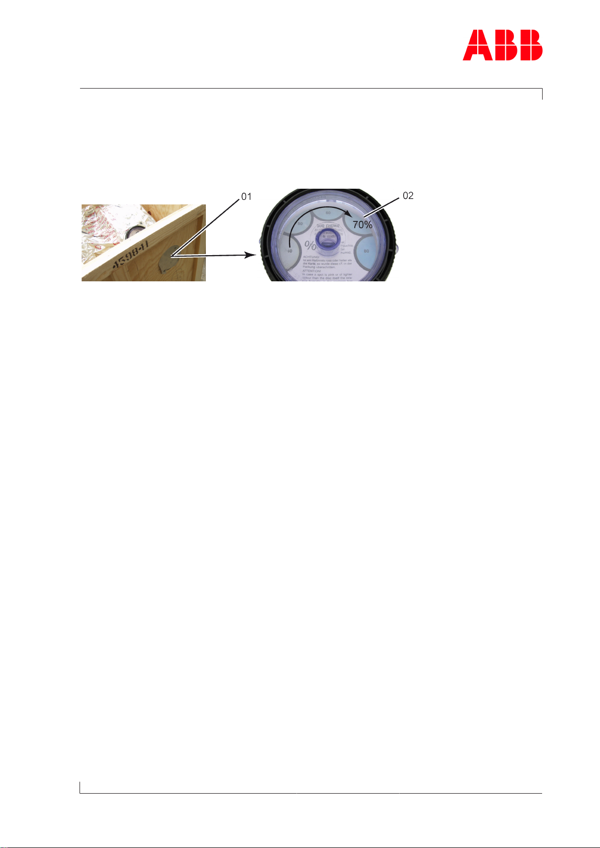
Fig.2: Volatile Corrosion Inhibitor (VCI)
Only dry rooms with 40...70 % atmospheric humidity, in which no water condensation can
form, are suitable as storage locations.
Storage of new low-pressure and high-pressure stages and cartridge groups for more
than 6 months (VCI)
WARNING
Health protection when handling VCI
VCI products are not hazardous in terms of the Ordinance on Hazardous
Substances. Nevertheless, the following points must be observed when
handling VCI:
uEnsure proper space ventilation.
uDo not eat, drink or store food at the workplace while working with VCI.
uWear safety gloves.
uClean hands and face after working with VCI.
uFor more information, see www.branopac.com.
Every 6 months, the following mothballing measures are required:
uOpen package.
uRemove VCI corrosion protection emitter from package and replace with a new VCI corro-
sion protection emitter of the same kind. New VCI corrosion protection emitters can be
obtained from www.branopac.com.
uOld VCI corrosion protection emitters must be disposed of in an environmentally compat-
ible, professional way and in compliance with locally applicable regulations.
uClose package. The more tightly the package is sealed, the longer the protection dura-
tion.
Page 6 / 8

Operation Manual / Power2 / 1 Introduction
1 Introduction / 1.5 Storage of new low-pressure and high-pressure
stages
© Copyright 2017 ABB. All rights reserved. HZTL4004_EN Revision D June 2017
Long-term storage of replacement low-pressure and high-pressure stages or
replacement cartridge groups
ABB Turbo Systems will prepare low-pressure and high-pressure stages or cartridge groups
for long-term storage if requested in the purchase order. The package is equipped with a hy-
grometer (see illustration).
Fig.3: Package with hygrometer
Every 6 months, the following measures are required:
uCheck the hygrometer(02) in the sight-glass. There is an opening(01) in the wooden
crate to enable you to perform this check. If the 70% indicator field has changed colour,
the maximum admissible atmospheric humidity has been exceeded. In this case, the low-
pressure or high-pressure stage or the cartridge group must be checked and repackaged
by an ABB Turbocharging Service Station.
uCheck the package for damage. If the package is damaged, the low or high-pressure
stage or the cartridge group must be checked and repackaged by an ABB Turbocharging
Service Station.
After every 3 years, the following steps must be carried out by an ABB Turbocharging Service
Station:
¡Checking the component
¡Replacing the desiccant
¡Repackaging the component.
Replacement components which are ready for operation
If the 70% field of the hygrometer (02) has not changed colour and the package is not dam-
aged, the replacement low-pressure or high-pressure stage or the replacement cartridge
group can be put into operation without previously having been checked by an ABB Tur-
bocharging Service Station.
Page 7 / 8

Operation Manual / Power2 / 1 Introduction
1 Introduction / 1.6 Contact information
© Copyright 2017 ABB. All rights reserved. HZTL4004_EN Revision D June 2017
1.6 Contact information
Contact information for the ABB Turbocharging Service Stations is available online.
uScan the QR code to access our website.
ABB Turbo Systems Ltd
Bruggerstrasse 71a
CH-5401 Baden
Switzerland
www.abb.com/turbocharging
Page 8 / 8

Operation Manual / Power2 800-M / 2 Safety
Table of contents
© Copyright 2019 ABB. All rights reserved. HZTL4025_EN Rev.B November 2019
Safety
1 Safety ...................................................................................................................... 2
1.1 Introduction .................................................................................................................... 2
1.2 CE conformity................................................................................................................. 2
1.3 Definition of mandatory signs .................................................................................... 3
1.4 Definition of safety instructions ................................................................................ 3
1.5 Intended use .................................................................................................................. 4
1.6 Deflagration on gas engines ....................................................................................... 5
1.7 Warning plates on the low-pressure and high-pressure stage ........................... 6
1.8 Rating plate of the high-pressure and low-pressure stage .................................. 7
1.9 Periodic check of the pressure vessels..................................................................... 8
1.10 Lifting of loads .............................................................................................................. 9
1.11 Prerequisites for operation and maintenance....................................................... 10
1.12 Hazards during operation and maintenance ......................................................... 11
1.13 Safe operation.............................................................................................................. 13
1.14 Safe maintenance ........................................................................................................ 14

Operation Manual / Power2 800-M / 2 Safety
1 Safety / 1.1 Introduction
© Copyright 2019 ABB. All rights reserved. HZTL4025_EN Rev.B November 2019
1 Safety
1.1 Introduction
The two-stage turbocharging system (Power2) manufactured by ABB Turbo Systems is state
of the art and complies with the respective health and safety standards in effect at the time
the system was built. Thus Power2 is safe to operate. Nevertheless, there may be some re-
sidual risks during operation of the Power2 and work on Power2 components, such as low-
pressure stage and high-pressure stage, which:
¡Are caused by Power2 itself or its accessories.
¡Are caused by the operating equipment used or supplies and materials.
¡Are a consequence of insufficient compliance with safety instructions.
¡Are a consequence of insufficient or inappropriate performance of maintenance and in-
spection work.
The operating company is responsible for defining measures that regulate safe access to
and safe handling of the Power2.
All instructions contained in this chapter must be observed for safe and trouble-free opera-
tion of the Power2 and during all work on the Power2 components.
All further safety instructions contained and specifically identified in every chapter of this
document (see section Definition of safety instructions) must also be observed.
1.2 CE conformity
Information
Low-pressure and high-pressure stages from ABB Turbo Systems comply with the Machinery
Directive 2006/42/EC and are partly completed machinery as defined by Article 2 g.
Page 2 / 17

Operation Manual / Power2 800-M / 2 Safety
1 Safety / 1.3 Definition of mandatory signs
© Copyright 2019 ABB. All rights reserved. HZTL4025_EN Rev.B November 2019
1.3 Definition of mandatory signs
To be worn at all times
Protective clothing Safety footwear to protect
against mechanical hazard and
risk of falling
Table1: Personal protective equipment to be worn at all times
To be worn specific to the respective task
Safety glasses Safety goggles
Safety gloves to protect
against
- Mechanical hazard
- Chemical hazard
- Thermal hazard
- Electrical hazard
Respiratory mask to protect
against
- Dusts
- Gases
Safety helmet Ear protection
Table2: Personal protective equipment to be worn specific to the respective task
1.4 Definition of safety instructions
WARNING
Definition of Warning
Non-compliance or inaccurate compliance with working or operating in-
structions indicated by this symbol and the word WARNING can lead to seri-
ous injuries to personnel and even to fatal accidents.
uWarning signs must always be observed.
CAUTION
Definition of Caution
Non-compliance or inaccurate compliance with working or operating in-
structions indicated by this symbol and the word CAUTION can lead to seri-
ous damage to engine or property with grave consequences.
uCaution signs must always be observed.
Page 3 / 17

Operation Manual / Power2 800-M / 2 Safety
1 Safety / 1.5 Intended use
© Copyright 2019 ABB. All rights reserved. HZTL4025_EN Rev.B November 2019
1.5 Intended use
Use on internal combustion engines
Power2 from ABB Turbo Systems is intended for charging internal combustion engines.
To ensure compliance with the machinery directive 2006/42/EC when using on gas engines,
the Power2 must be operated in an engine room classified as "not at risk of explosion". This
is in accordance with the position paper [2] relating to ATEX issued by EUROMOT[1].
The specific operating limits of Power2 were determined on the basis of information from
the enginebuilder about the intended use. This data is given on the rating plate and is gener-
ally different for the low-pressure stage and high-pressure stage.
ABB accepts no liability and rejects all warranty claims for any non-intended uses.
[1]Euromot = The European Association of Internal Combustion Engine Manufacturers
[2]Directive 94/9/EC concerning equipment and protective systems intended for use in po-
tentially explosive atmospheres (ATEX) The Euromot Position as of November 2003, ATEX
Euromot Position 191103
WARNING
Unapproved operation
Operation of the Power2 outside of the operating limits can be hazardous to
personnel.
uPower2 must only be operated within the operating limits.
uPower2 must only be operated by trained personnel.
The intended use of the Power2 includes compliance with all regulations and conditions.
In particular, the following must be observed:
¡The Operation Manual
¡The instructions of the enginebuilder
State of the art
The Power2 is designed and built according to the state of the art and is safe to operate.
Perfect condition
The Power2 must be used in a technically perfect condition and in compliance with its inten-
ded use.
ABB Turbo Systems excludes any liability for damage resulting from unauthorized modifica-
tions to the Power2 or improper operation.
Page 4 / 17

Operation Manual / Power2 800-M / 2 Safety
1 Safety / 1.6 Deflagration on gas engines
© Copyright 2019 ABB. All rights reserved. HZTL4025_EN Rev.B November 2019
1.6 Deflagration on gas engines
Low-pressure stages from ABB Turbo Systems can tolerate a deflagration with a transient
pressure increase of 12bar (guideline value).
High-pressure stages from ABB Turbo Systems can tolerate a deflagration with a transient
pressure increase of 15bar (guideline value).
After a deflagration event ABB Turbo Systems recommends verifying the following points on
the low-pressure and high-pressure stages:
¡Position of the turbine and compressor casings to the bearing casing
¡Shifting of the bearing casing in relation to the bracket
¡Cracks in casings
If during external inspection anomalies are found or if a particularly strong deflagration
event has taken place, it is also recommended to check the bearings of the low-pressure and
high-pressure stages before the next start. This inspection and evaluation must be carried
out by an ABB Turbocharging Service Station.
Page 5 / 17

Operation Manual / Power2 800-M / 2 Safety
1 Safety / 1.7 Warning plates on the low-pressure and high-pressure
stage
© Copyright 2019 ABB. All rights reserved. HZTL4025_EN Rev.B November 2019
1.7 Warning plates on the low-pressure and high-
pressure stage
Warning plates are attached to the low-pressure and high-pressure stage, and must be com-
plied with. The warning plates must always be present in the intended locations and must be
legible.
Fig.1: Warning plate
If warning plates are not present in the intended locations or are not legible, they must be
replaced with new warning plates. The information that is required can be found in the Oper-
ation Manual / Product description.
Low-pressure and high-pressure stages supplied to the enginebuilder without insulation
must be retrofitted with warning plates to be affixed to the insulation. This is the responsib-
ility of the enginebuilder.
Page 6 / 17

Operation Manual / Power2 800-M / 2 Safety
1 Safety / 1.8 Rating plate of the high-pressure and low-pressure stage
© Copyright 2019 ABB. All rights reserved. HZTL4025_EN Rev.B November 2019
1.8 Rating plate of the high-pressure and low-
pressure stage
Fig.2: Rating plate
Operating limits
1 Operating limits at engine overload (110 %). In test rig operation only, unless otherwise
agreed with the enginebuilder.
2 Operating limits during operation
Table3
Recommended replacement intervals
3 Replacement interval of plain bearings in 1000 h
4 Replacement interval of compressor in 1000 h
5 Replacement interval of turbine in 1000 h
Table4
Further data
6 Power2 designation
7 Power2 serial number
8 Power2 stage
9 Serial number of the low or high-pressure stage
10 Year of construction of the low or high-pressure stage
11 Weight of the low or high-pressure stage
12 Part number of the customer of the low or high-pressure stage
Table5
Page 7 / 17

Operation Manual / Power2 800-M / 2 Safety
1 Safety / 1.9 Periodic check of the pressure vessels
© Copyright 2019 ABB. All rights reserved. HZTL4025_EN Rev.B November 2019
Explanations of the rating plate
The recommended replacement intervals and the corresponding operating limits are jointly
defined with the enginebuilder. This information is specific to the system.
The operating limits of the low-pressure stage are generally different from the operating
limits of the high-pressure stage.
Operation above the indicated values nBmax, tBmax can considerably shorten the recommended
replacement intervals. In such cases ABB recommends contacting the nearest ABB Tur-
bocharging Service Station.
nMmax, tMmax normally apply only when running at overload (110%) during trials on the engine
test bed. These limit values can also be permitted during operation for special applications.
Operation above nMmax and tMmax is not permitted.
Non-observance of the recommended replacement intervals increases the risk of unpredict-
able component failures.
Locations of the rating plates
The locations of the rating plates are defined in the Operation Manual, Chapter 4 Product
description.
1.9 Periodic check of the pressure vessels
The pressure vessels used by ABB Turbocharging, such as those for wet or dry cleaning, are
so-called "simple pressure vessels".
¡The locally applicable legal regulations regarding periodic checks of the pressure vessels
must be observed.
¡The operating company is responsible for the safe operation of the pressure vessel.
WARNING
Danger due to pressure vessels
The operating company must make sure the pressure vessels are in proper
working condition and monitor them. Necessary repair or maintenance work
must be performed promptly, and the required safety measures must be
taken.
uPressure equipment must not be operated if defects are present.
Page 8 / 17

Operation Manual / Power2 800-M / 2 Safety
1 Safety / 1.10 Lifting of loads
© Copyright 2019 ABB. All rights reserved. HZTL4025_EN Rev.B November 2019
1.10 Lifting of loads
WARNING
Suspended loads
Loads that are not attached according to regulations can cause injury to
personnel or fatal accidents.
uLoads must always be fastened to properly functional lifting gear with a
sufficient load limit.
uPay attention to the correct attachment of loads on the crane hook.
uPeople must not stand beneath suspended loads.
Wear safety gloves to protect against mechanical hazards.
Wear safety helmet.
Fig.3: Attachment of loads on the crane hook
Fig.4: Attachment angle
If there are two or more suspension points, the attachment angle of 45° must not be ex-
ceeded. This prevents excessive loading due to diagonal pull.
uBefore looping around the components of the low-pressure and high-pressure stage, al-
low them to cool down (maximum 80°C).
uAttach components of the low-pressure and high-pressure stage as described in the re-
spective action steps.
uUse a suitable edge guard if there are sharp edges.
uThe assembly devices must be completely screwed in and must not unscrew during use.
uUse assembly devices only for the described applications.
uPut down dismantled components of the low-pressure and high-pressure stage in such a
way that they cannot tip over.
Page 9 / 17

Operation Manual / Power2 800-M / 2 Safety
1 Safety / 1.11 Prerequisites for operation and maintenance
© Copyright 2019 ABB. All rights reserved. HZTL4025_EN Rev.B November 2019
1.11 Prerequisites for operation and maintenance
Responsibility of the operating company
In awareness of its responsibility, the operating company must ensure that only authorised
personnel work on the Power2, who:
¡Are versed in the general and locally applicable regulations for occupational safety and
accident prevention
¡Are equipped with the prescribed personal protective equipment
¡Have read and understood the Operation Manual
¡Have been instructed in the use of the Power2.
The safety-conscious work of the personnel and adherence to the Operation Manual must be
checked periodically.
Suitable working materials and personal protective equipment must be kept in a perfect
condition.
Only authorised personnel may remain in the vicinity of the Power2 when the engine is run-
ning.
Competence of personnel
The Power2 may only be operated and serviced by trained and authorised personnel. Basic
mechanical training is a prerequisite.
Modifications to the Power2
Modifications to the Power2 must be approved by ABB Turbo Systems.
Original parts and safety
Original parts and accessories must be specially designed by ABB Turbo Systems for the
ABB Power2.
WARNING
Use original parts
Operation of the Power2 with non-original parts can impair the safety of the
Power2 and can cause serious damage to property and injury to personnel.
uOnly use original parts from ABB Turbo Systems.
ABB Turbo Systems accepts no liability for any damage resulting from the use of non-ori-
ginal parts and corresponding accessories.
Page 10 / 17
Table of contents
Other ABB Industrial Equipment manuals
Popular Industrial Equipment manuals by other brands

Tsubaki
Tsubaki CR3812 Installation

Festo
Festo HGPM-xxx-G series operating instructions

Shibuya Hoppmann
Shibuya Hoppmann Cap Star FCCPSTLDSA Installation & maintenance manual

Jerguson
Jerguson JMT Series Installation, operation & maintenance instructions

Matsing
Matsing MS-MBA-3.3-C4A3-H4A2 instruction manual

John Crane
John Crane 4610 Installation, operation & maintenance instructions