STS M2 Series User manual

Surface to Surface Inc. ®
Operators Manual
** M2-E **
USE IN CONJUNCTION WITH OEM MANUALS (ENCLOSED)
Unit Serial No. _______________
Teco-Westinghouse Motor
Optim HE PLUS – Serial No. ______________
Gorman-Rupp® Pump
STS-GR82E2 – Serial No. ________________
Links relating to this Manual
www.stsmixers.com
www.grpumps.com
www.twmi.com
STS-103 Rev. 11/07/23 www.stsmixers.com
Dealer

2
*** NOTICE ***
THIS UNIT IS TO BE INSTALLED, SET-UP, AND
WIRED BY A QUALIFIED ELECTRICIAN TO BE
COMMISSIONED BY THE END USER (CUSTOMER).
ALL CODES AND REGULATIONS ARE TO BE
FOLLOWED. SURFACE TO SURFACE ASSUMES NO
RESPONSIBILITY FOR DAMAGES OR PERSONAL
INJURIES CAUSED BY IMPROPER INSTALLATION.
If a problem or concern is found while installation is
being done, a call to the appropriate party is
recommended.
Teco-Westinghouse West 1-800-661-4023
East 1-800-268-4770
Surface to Surface Inc. 1-800-567-0978
STS-024 Rev. 01/04

3
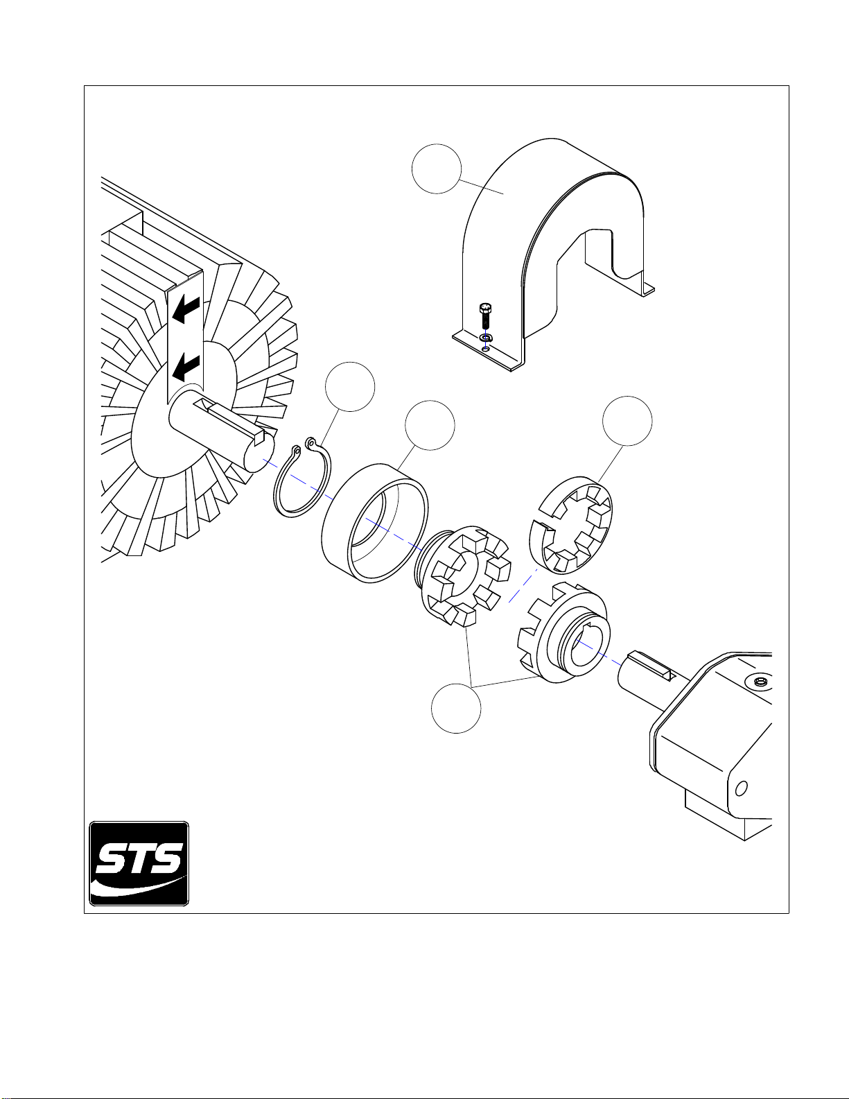
****** CAUTION ******
BEFORE STARTING THIS MOTOR, DISENGAGE THE
MOTOR/PUMP COUPLER (see FIG. 1) AND CHECK THE
MOTOR FOR PROPER ROTATION (see decal). IF THIS STEP
IS NOT FOLLOWED, THE IMPELLER MAY BECOME
SEPARATED FROM THE SHAFT AND CAUSE SUFFICIENT
DAMAGE TO THE PUMP AND IMPELLER AND OR
PERSONAL HARM.
To disengage the coupler, remove the guard (1). Using external snap ring
pliers, spread the snap-ring (2) and remove it from the groove in the coupler
(5) and backwards over the motor shaft. Now slide the retainer (3) also
backwards and over the motor shaft. The plastic fingered insert (4) is now
exposed. The insert (4) is a 1 piece split flexible unit and can be worked out
from between the 2 couplers (5) and set aside.
You can now power the motor to check rotation without rotating the pump.
Switch the motor on/off and as the shaft slows down, you will be able to see
the rotation direction. If the need be, change the wiring to provide the
proper rotation. Once proper rotation is established (see arrow decals) the
drive coupler can be reassembled in the reverse order as previously
explained.
IF A VARIABLE FREQUENCY DRIVE (VFD) IS USED IN
THE WIRING OF THE MOTOR OF THE MIXER, THE
REVERSE FUNCTION (IF EQUIPED) MUST BE DISABLED.
IF THIS FUNCTION IS NOT DISABLED, THE MOTOR CAN
INADVERTEDLY BE REVERSED BY THE OPERATOR AND
THE IMPELLER MAY BECOME SEPARATED FROM THE
SHAFT AND CAUSE SUFFICIENT DAMAGE TO THE PUMP
AND IMPELLER AND OR PERSONAL HARM.
To disable the reverse function (if equipped) refer to the manufacture’s
installation manual of the variable frequency Drive (VFD) or contact the
VDF manufacturer.
STS-024 Rev. July/2021
4
1
2
34
5
FIG. 1

5
TABLE OF
CONTENTS
PAGE
STS Inc. Warranty…………………….….……………………………….. 8
Safety Statements………………………………………………...………… 9-12
Safety Markings……………………………………………………………. 13
Main Working Components (Photo)……………………………………… 14
M2-E Hose Connections ……………….………………….……………. 15
Introduction to the M2 ……………….………..………..…………. 16
M2-E Foot Print (top view)……………………………….…………… 17
M2-E General Data Sheet…………………………………………………. 18
Identifying Your Machine & Components………………………………. 19
SECTION II (Description, Care and Maintenance)
Electrical powered centrifugal pump.…….…………….………….…. 21-24
Filter shear system……………………………………………………. 25-26
Venturi mixing tee……………………………..………..……………. 27
Wash wand……………………………………………………...……. 28
Dry hopper with table & hopper valve…………………………..…… 29
Internal tank jets ……………………………………...……………… 30-31
SECTION III (Set-up and installation of unit in Detail)
Permanent mounting of unit…………………………...…………….. 33
Portable use of unit…………………….…………………….………. 33

6
TABLE OF
CONTENTS
PAGE
SECTION IV (Operating the M2-E Unit.
Site set-up and pre-check…………………………………………….. 35
Starting the motor driven pump…………….….…....…….……… 36
Typical mixing operation……………………….……………………. 37-38
Typical transfer / off-loading operation……………………………… 39
Shutdown, cleanup & storage
Warm weather…………………………………….…………. 40
Cold/ freezing weather………………………………….…… 41
Prolonged periods of storage………………………………… 42
SECTION V (Trouble shooting)
Trouble Shooting the M2-E ………….…….….….…..…….....…… 44-45
SECTION VI (Periodic Maintenance & Repair Information)
Maintenance Schedule…………………….….………………….…... 47
Centrifugal Trash Pump Seal Replacement………………………..… 48
Bolt torque Specifications…………………………………….……... 49
Notes…………………………………………………….…………… 50

7
TABLE OF
CONTENTS
PAGE
SECTION VII (OEM Repair / Information)
GR Centrifugal Pump Owner’s Manual……………………..………… 52-63
Teco-Westinghouse Owner’s Manual excerpts …….…...….….….…. 64-70
Gruvloc® Pipe Couplings ………….…….….….………………..…… 71-73
Quick-Flex® Drive Coupling ………….……….….……………..…… 74-77
SECTION VIII (Parts Manual)
M2-E PARTS MANUAL…………………….…………….……. 79-81

8
Limited Warranty
United States and Canada
Surface to Surface Inc. or its subsidiary which last sold the product, warrants new products sold by it for use in the
United States and Canada to be, at the time of manufacture, free from defects in workmanship and materials. This
warranty covers for a period of Twelve (12) Months of operation from the date of delivery for initial use, whichever
comes first.
Exclusions and Additional Limitations
1. This warranty relates to the condition of the product at the time of manufacture and does not cover parts or
service as a result of:
(a) Normal wear and tear or required maintenance including, without limitation, adjustments or replacement of
components subject to wear and tear, such as belts, hoses, seals and/or packing, fuses, bulbs,
switches and ignition parts.
(b) Abuse including, without limitation, neglect, improper operation, misapplication, overloading, accident or
alterations not approved by Surface to Surface Inc.
(c) Lack of maintenance, including, without limitation, failure to inspect and maintain, improper repair, use of
“unapproved parts”, cracked engine heads and blocks unless caused by the failure of
an internally lubricated part or repair of engine valves, rings or guides.
2. The Company’s warranty does not apply to purchased components manufactured by others where separate
warranty is made by the manufacture of such components and will be applied as interpreted by
the supplier.
3. All claims under his warranty shall be submitted in writing by the distributor to the Company, which will be the
sole judge in determining the merits of the claim.
4. The company shall have the right to have all products or parts claimed to be defective returned to it and the
cost of shipping such items shall be borne by the distributor.
……………………………………………………………………………………
Warranty Registration Card
In order to help us provide complete service for our product, please complete this card and return it.
If not returned, all requests for warranty will be denied.
Print Name: …………………………………………………………………….….
Address: …………………………………………………………………………...
City: ……………………State/Province………………Zip/PC…………………...
Model No. ………………………….. Serial No. …………………………………
Date of Purchase ………………………… Dealer ………………………………..
Return to: Surface to Surface Inc.
5150 Forest Rd. RR#3
Watford, Ontario, Canada
N0M 2S0
01/14/08

9
M2-E
SAFETY STATEMENTS
Your personal safety and the safe operation of this unit are the concern of Surface to Surface Inc., and by
reading and understanding this manual and understanding the safety statements, you will decrease the risk of
personal and equipment damage.
Safety statements are listed here and throughout this manual to draw your attention to potential hazards that
may be encountered while operating this piece of equipment. While reading this manual, you will notice that
certain safety statements will relate directly to the operation, or maintenance of that particular part of the unit and
should be followed carefully. Decals on the unit also follow the same format as the warnings in this manual, and
therefore should be kept in good repair to alert the operator and others of the potential hazard.
The engine / motor manual also contains hazard warnings which pertain to the engine / motor and should
also be followed.
This safety alert symbol appears with most safety statements.
It means attention, become alert, your safety is involved!
Please read and abide by the message that follows the safety alert symbol.
DANGER
WARNING CAUTION
CAUTION
Caution "without the safety alert symbol"
indicates an potentially hazardous
situtation that can cause damage to the,
machine, personal property and / or the
environment or cause the machine to
operate improperly.
Danger (the word "DANGER" is in white
letters with a red rectangle behind it)
indicates an imminently hazardous
situation, which, if not avoided, will
result in death or serious injury.
Danger is limited to the most extreme
situations.
Warning (the word "WARNING" is in black
letters with an orange rectangle behind it)
indicates an potentially hazardous
situation which, if not avoided, could
result in death or serious injury.
Caution (the word "CAUTION" is in black
letters with a yellow rectangle behind it)
indicates an potentially hazardous
situation which, if not avoided, may
result in minor or moderate injury.

10
M2-E
SAFETY STATEMENTS
The following caution statements have been drawn from the instructions in this manual. They
have been assembled here for ready reference.
WARNING
NEVER USE BODY PARTS,
OR FOREIGN OBJECTS
in an attempt to unplug or clean the
hopper v alv e or mixing tee.
Serious personal inj ury or
damage will result.
WARNING
Serious personal injury will result.
DO NOT REMOVE OR MODIFY
SAFETY COVERS OR GUARDS.
WARNING
while the unit is in operation.
Serious personal inj ury will result.
NEVER ATTEMPT TO REMOVE
OR CLEAN THE FILTER SHEAR
CAUTION
DO NOT POSITION
ANY PART OF YOUR BODY
over the hopper, valve,
or mixing tee while cleaning.
CAUTION
WHEN THE UNIT
IS IN OPERATI ON,
the fluid in the piping may reach
pressures up to 50 p.s.i.
IN AN EMERGENCY
shut off all power (switch)
to halt the motor, pump, and fluid flow
DANGER
NEV E R A T T EM P T REP A I RS
OR DISASSEMBLY
without shutting off the motor and
disconnecting/lock-out the power source.
Serious personal inj ury will result.
DANGER
11
M2-E
SAFETY STATEMENTS continued
The following caution statements have been drawn from the instructions in this manual. They
have been assembled here for ready reference.
CAUTION
TRAPPED FL UID MAY BE PRESENT
and will spill out when p iping, hoses,
pump or filter shear are removed.
CAUTION
AVOID ALLOW ING FORE IGN MAT ERIAL
into the Vent uri Mixing Tee thr u the
Hop per, by keeping th e v alv e c losed
when not in use.
CAUTION
NEVER LEAVE LIQUID IN THE
PUM P CASIN G, PIPIN G, OR HOSES
durin g freezing weather condit ions,
as damage will result.
Follow instruction for winterizing.
CAUTION
CAUTION
CARE MUST BE TAKEN W HEN
INSTALLING TH E COUPLER GASK ETS.
If the gaskets are not properly lubricated
and in stalled, a leak may dev elop.
IMPR OPER IN STALLATION OF THE
MECH ANICAL o r GREASE SEAL
will result in leakage and possible
damag e to the seal. All mainten ance,
operating and repair of th is unit, must be
done per the instruct ions in t he oper ators
man ual for safety and reliability.
CAUTION
WH EN TRANSFERRING F LUID
to the drill ri g, fluid pressure may
reach or exceed 50 p .s.i.
CHECK the d rill rig manufact urers
speci fications r egarding maximum inlet
pres sures all owed f or their pu mp.
CAUTION
BEFORE STAR TING OR RESTAR TING
the motor and centrifugal pump, make
sure an y valves installed on the pump
suction inlet line are open, and the
fluid level in the tank is above
the suct ion line.
CAUTION
C h e ck t h e p u mp b y sl o wl y & c ar e f u l l y
opening the plug located on the top
of the centrifugal pump discharge elbow.
A visual inspection can be made if the fluid
escapes around the plug as it is loosened.
Remove the plug to view inside fluid level.
The centrifugal pump seal W ILL be
damaged if allowed to cavitate or run dry.
BEFORE STARTING THE MOTOR,
BE SURE THE PUMP IS PRIMED!

12
M2-E
SAFETY STATEMENTS continued
The following caution statements have been drawn from the instructions in this manual. They
have been assembled here for ready reference.
CAUTION
The manufacture r should be consulted
whe n considering alternativ e uses
for this piece of equipment.
This unit was de signe d for t he mix ing
and sheari ng of a dry additive, into a
liquid stre am.
Other uses may create unfores een safety
issues and personal inj ury r isk.
CAUTION
LIFTING LU GS OR THE L IFTING POINT(S)
identified and labelled on the skid
structure must be used in orde r to
safe ly lift and tra nspor t the unit.
WARNING
REFER TO THE SAFETY
STATEMENTS IN THE
OEM SUPPLIED MANUALS
AND
THIS MANUAL
REGARDING THESE
OPERATIONS.

13
M2-E
Safety Markings
Hazard and warning markings have been placed at appropriate points on the unit. International symbols
have been used, in order to ensure universal understanding of the nature of the hazard. Please comply
with all warnings and markings to ensure safe use of the equipment. These include but are not limited to:
a) Lifting points b) Flammable Liquids
c) High temperature areas d) Personal Protection recommendations
e) Personal dangers f) Equipment dangers
g) Operating instructions h) Fluid flow direction
SOME EXAMPLES THAT MAY BE FOUND ON THE EQUIPMENT
Liftin
g
Point
Personal Protection
,
Read and understand O
p
erator’s manual and Maintenance manual
Hot Surface
Fluid Flow Direction
Maintenance Instructions
Liftin
g
Point
CLEAN FILTER DAILY

14
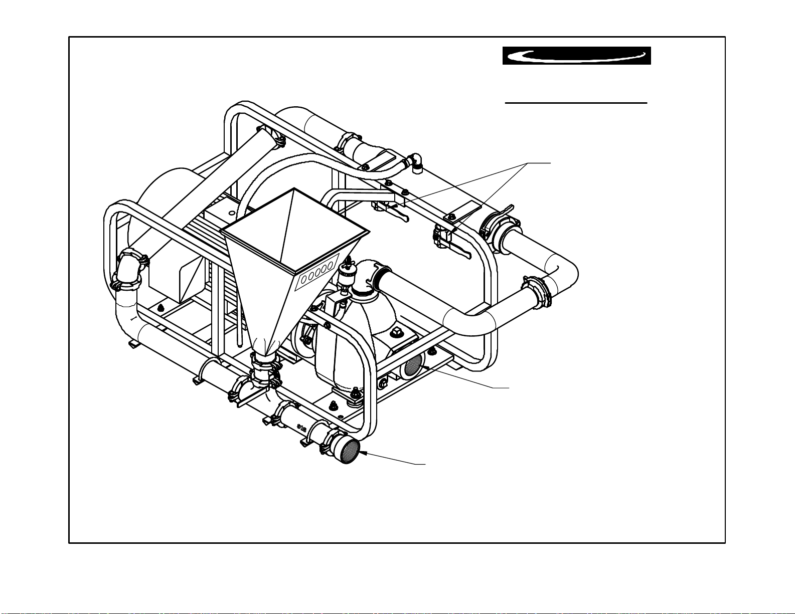
15
"ALL HOSES SHOULD BE KEPT TO THE SHORTEST LENGHT POSSIBLE TO ACHIEVE MAXIMUN PREFORMANCE."
(Hose Hook-ups)
Surface to Surface Inc.
M2Series
FLUID OUTLETS
[to Drill Rig & Tank Guns]
**1 1/2" NPT**
** 2" NPT**
PUMP INTAKE
[in from Tank]
This line should have a valve installed at
the tank to facilitate shut down or reapirs.
FLUID RETURN
[out to Tank]
Thisline should discharge above themaximun fillline
of the tank. Theair space will stopthe siphon action of the fluid.
** 2" NPT**

16
M2-E
Operators Manual
Congratulations on your acquisition of the world renowned M2 Mixing System. You have acquired the
fastest and most efficient mixing system manufactured for mixing Bentonite drilling slurry (mud). As a
manufacturer of HDD support equipment, we are well aware of the extreme conditions that HDD
equipment is exposed to on a daily basis. Surface To Surface Inc. strives to overcome these conditions,
with better design and manufacturing practices. Please feel free to call our toll free number
(1-800-567-0978) if you have any questions or concerns about your M2 series mixer.
Thank you, for choosing the M2 series mixer.
The M2 mixing unit was designed to mix dry or liquid drilling products with clean
water, into a slurry. The slurry is continually circulated through the mixing cycle until it
reaches the desired consistency. The operator can then transfer the final product to a holding
reservoir or directly to the drilling equipment.
The M2-922 mixing unit consists of an electric powered centrifugal pump, filter/shear
unit, venturi mixing tee assembly, dry hopper with a table, a set of tank internal jets
(customer installed).
These components are all mounted on a frame type skid, built for lifting or solid mounting.
For ease of interpretation, looking at the mixing unit hopper straight on will be considered
looking at the front of the unit. Hence the other long side, will be the rear and the ends will be
right or left end.
RECORD OF OWNERSHIP:
• Unit Serial No. __________________________________________
• Motor Serial No.________________________________________
• Pump Serial No:_________________________________________
• Date Purchased/Leased:___________________________________
• Dealer Purchased/Leased From:_____________________________
• Special Custom Features:__________________________________

17
46 1/2"
31 1/2"
27"
REV.
DA TE.DWR. NUM.
Surface to Surface Inc.
®
* Due to ourcontinuing product improvement, specifications are subject to change without notice. *
M2-E (Electric)
M2-E Footprint
02 / 27 / 18
Dry Weight: 460 Lbs (209 Kg)
18
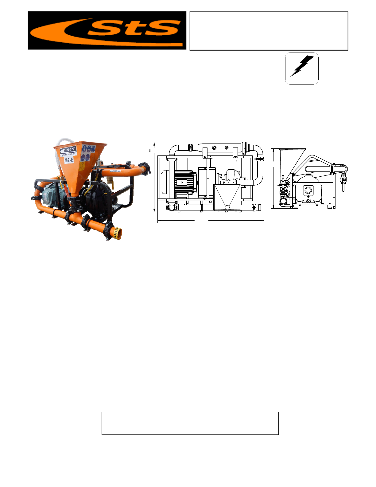
Specifications M2-E922 Mixer Benefits
Dimensions 31 1/2” W x 46 ½” L x 27” H Small space saving footprint.
Weight 460 lbs. (209 Kg) Light weight for easy transportation.
Hopper Height & Size 27” High Holds ½ of a bag Low hopper height reduces back strain.
Mixing System 2” Proprietary StS Mixing System Fast & efficient with high shearing ability.
Flow Valves Brass and Steel construction Withstand the abuse of daily operations
Skid Frame 1” steel tube with lifting bale Built tough for the construction trade.
Motor 10 HP Teco 230V/460V 60Hz Industrial rated for longer service life
Pump 2” Cast iron centrifugal trash pump Gorman-Rupp 80 series
Pump / Motor Connection Bearing Block to Lovejoy® Coupler Large bearings & oversized coupler (service life)
Pipe Couplers Bolt & Snap-groove type Fast cold weather draining of system.
Pressure Wand Hopper maintenance wand Removal of build-up caused by additive.
Internal Jet Guns (supplied) Eductor Nozzles (5-1 fluid output) Fast and effective rolling and mixing action.
Mechanical Seal Self-Pressurizing Grease Seal Greaseable seal for more rugged working conditions
Replaceable Wear Plate Hardened plate ahead of Impeller Less wear on internal pump parts and is replaceable.
With a 40 second viscosity, the M2 produces 90 gpm @ 36psi through the nozzle and 52 gpm @ 36psi to the tank
internal jet guns (5-1 mixing equals 260 gpm of mixing / rolling action in tank) and a discharge rate of 80 gpm @
36psi
Features and Benefits M2-E Mixer
The M2-E universal mixer is designed around the time proven M series mixers of STS. Powered by a 10HP
Teco/Westinghouse electric motor, driving a 2” centrifugal pump, making effective use of the proprietary 4 point mixing
system. The M2-E may be used as a new installation or retrofitted into an existing system of tank(s). Since the unit is
connected by hoses and not hard pipe, the placement of the mixer verses the tank(s) is less restricted and a
configuration to suit the needs of the contractor is easier to achieve. The small size also makes it a portable,
independent unit that is easier to transport from site to site.
Surface to Surface Inc.
Also available in Hydraulic (M2-H), Diesel (M2-D) or Gasoline (M2-G) models.
∗∗∗ All Specifications Subject to Change Without Notice ∗∗∗
Universal 2” Mixer
Model M2-E
Surface to Surface Inc.
5150 Forest Road, R.R.#3, Watford, Ontario, N0M 2S0
Tel: 1-800-567-0978
Check our website for the latest products and specifications
www.stsmixers.com
03
/
09/18
Electric
46 1/2"
31 1/2"
27"
19
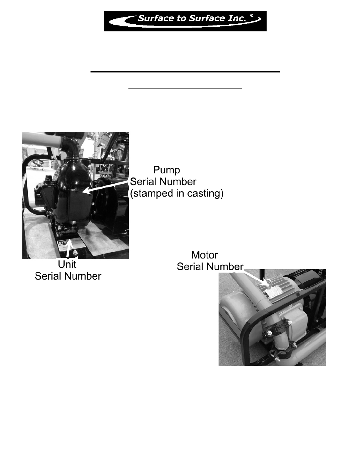
M2-E
Identifying Your Machine & Components
Location of Tags and PIN Plates

20
SECTION #II
Description, Care and Maintenance
This manual suits for next models
2
Table of contents
Other STS Industrial Equipment manuals


Popular Industrial Equipment manuals by other brands

Meler
Meler 200-ST Series Technical manual

General Measure
General Measure Checkweigher user manual

Vega
Vega VEGASON 64 operating instructions

WERMA Signaltechnik
WERMA Signaltechnik KombiSIGN 71 manual

Ecotech Italia
Ecotech Italia DW45 Manual for use and maintenance

SCHUNK
SCHUNK SWS-I-011 Assembly and operating manual


