Beisler 1265-4 User manual

Working Instructions Automatic Single-Head Serging Machine Beisler GmbH
A-1
Working Instructions
Working Instructions
Automatic Single-Head Serging Machine 1265-4
Valid: 01-2003 A

Working Instructions Automatic Single-Head Serging Machine 1265-Beisler GmbH
A-2
Contents of the working instructions
The working instructions are divided into four sections:
A. General notes
Safety instructions for the operating and service personnel and for the
operator of the achine.
B. Operating instructions
Instructions for the personnel operating and handling the achine.
C. Service instructions
Instructions for the personnel in charge of the initial start-up, setting up
and service of the achine.
D. Progra ing instructions
Instructions for the service personnel in charge of preparing and setting
up the achine.
Scope of the working instructions
These working instructions describe the AUTOMATIC SINGLE-HEAD
SERGING MACHINE 1265-4 of Beisler G bH and apply only to those
achine parts and co ponents that are standard equip ent of the AU-
TOMATIC SINGLE-HEAD SERGING MACHINE 1265-4.
They do not apply to accessories or achine parts (e.g. sewing head)
fro third parties that the achine is equipped or retrofitted with. For
those co ponents, the working instructions of the respective anufac-
turer or supplier apply.

Working Instructions Automatic Single-Head Serging Machine Beisler GmbH
A-3
Section A General notes

Working Instructions Automatic Single-Head Serging Machine 1265-Beisler GmbH
A-4
Contents
A.1 Safety instructions ............................................................................... A-5
A.1.1 Exclusion of liability ..................................................................... A-5
A.1.2 Copyright ..................................................................................... A-5
A.1.3 I portant infor ation for the operator ........................................ A-6
A.1.4 Warranty ...................................................................................... A-6
A.1.5 I portant infor ation for the operating personnel ..................... A-7
A.1.6 I portant infor ation for the service personnel ......................... A-7
A.2 Explanation of sy bols ....................................................................... A-8
A.2.1 Sy bols used in the working instructions .................................. A-8
A.2.2 Sy bols used on the achine ................................................... A-8
A.3 Use of the device ................................................................................... A-9
A.3.1 Correct use .................................................................................. A-9
A.3.2 Incorrect use ............................................................................... A-9
A.4 Safety require ents ........................................................................... A-10
A.4.1 Standards and directives .......................................................... A-10

Working Instructions Automatic Single-Head Serging Machine Beisler GmbH
A-5
A.1 Safety instructions
A.1.1 Exclusion of liability
Beisler G bH warrants the faultlessness of the product as set forth by
their advertise ent, product infor ation and these working instructions.
Other product characteristics are not warranted.
Beisler G bH is not responsible for the profitability or for the correct
function of the auto atic single-head serging achine 1265-4 if it is
used for other purposes than those defined in section Correct use.
Beisler G bH is not responsible for da age that arises fro the use of
non-defined and non-approved spare parts or accessories.
A.1.2 Copyright
© 2002 Beisler G bH, Hösbach
Auto atic single-head serging achine
The auto atic single-head serging achine 1265-4 and all related
parts are protected by copyright. Any reproduction of the achine will
be prosecuted.
Working instructions
These working instructions are protected by copyright. No part of the
working instructions, including figures and tables, ay be reproduced
or translated in any for or by any eans, electronic or echanical, wi-
thout the express written per isson of Beisler G bH.
Beisler G bH
Frohnradstr. 10
63768 Hösbach
Deutschland
Phone: ++ 49 / 6021 / 50 19 0
Fax: ++ 49 / 6021 / 50 19 10
eMail: vertrieb@beisler-g bh.de

Working Instructions Automatic Single-Head Serging Machine 1265-Beisler GmbH
A-6
A.1 Safety instructions
A.1.3 Important information for the operator!
This achine has been anufactured in keeping with the latest techno-
logical develop ents and is operationally safe. However, it ay present
potential hazards, particularly if it is operated by inadequately trained
personnel or if it is not used correctly:
For personnel operating and handling the achine, the operator
ust prepare written instructions in a reasonable for and in the
language of the operating personnel based on these working in-
structions (Ger any: Accident Prevention Regulations UVV VGB 1 §
7.2).
Use the operating instructions to fa iliarize the operating person-
nel with the functions, operation, and care of the achine and
check to see if the operating personnel fully understands these in-
structions.
Use the service instructions to fa iliarize the service personnel
with the setting up and aintenance of the achine.
For any odifications of the achine that have not been approved
by Beisler G bH in writing, the operator is fully responsible.
The contents of the working instructions are subject to change wit-
hout further notice.
Concerning translations into foreign languages, the Ger an versi-
on of these working instructions is binding.
Should you encounter proble s that are not entioned in these
working instructions, please contact your supplier i ediately for
your own safety. Please do not hesitate to contact Beisler if you
have any suggestions that help to i prove this product.
Keep these working instructions close to the achine so that
safety instructions and infor ation on operation, setting-up,
and aintenance are always accessible.
Warranty
Beisler G bH warrants the safety, operatability, and repair without char-
ge of the auto atic single-head serging achine 1265-4 for a period of
6 onths under the condition that:
the achine is used exclusively for the intended purpose and ser-
viced in accordance with the infor ation in these working instruc-
tions,
odifications of the achine are carried out only with prior written
approval of Beisler G bH,
only original spare parts or accessories approved by Beisler G bH
are used. For a co plete list of all approved spare parts, please
contact Beisler G bH.
If the achine is used for ore than 10 hours per day (shift operation),
the warranty period is reduced to 3 onths.
The warranty period starts with the delivery of the achine to the ope-
rator.

Working Instructions Automatic Single-Head Serging Machine Beisler GmbH
A-7
A.1 Safety instructions
A.1.5 Important information for the operating personnel!
Please note that any work to the auto atic single-head serging achi-
ne 1265-4 ust be carried out only by trained operating personnel:
Operating personnel eans persons:
that have been given initial instructions for sewing auto ats and that
have been trained for the operation and handling of the auto atic
single-head serging achine 1265-4 on the basis of these operating
instructions,
that have been infor ed about potential risks arising fro their work
with the achine,
that are capable of assessing their work with the achine due to oc-
cupational experience and instruction of the safety regulations and
of recognizing potential hazards during work,
Cleaning of the achine or of achine parts ust be perfor ed only
by personnel that has been infor ed about potential hazards arising
during the cleaning work.
Prior to the initial operation of the auto atic single-head serging a-
chine 1265-4, read the operating instructions carefully so that you
can ake full use of the advantages of the achine and to prevent
da age.
A.1.6 I portant infor ation for the service personnel!
Please note that service work to the auto atic single-head serging a-
chine 1265-4 ust be carried out only by authorized and adequately
trained expert personnel:
Expert personnel eans persons:
that have aquired their expertise by a special training in achine
technology or electrical engineering or by a special advanced trai-
ning or a co parable qualification,
that have acquired the knowledge required to perfor all works for
setting up and servicing the auto atic single-head serging achine
1265-4 fro a training by Beisler G bH,
that are capable of assessing their work with the achine due to oc-
cupational experience and instruction of the safety regulations and
of recognizing potential hazards during work.
Prior to carrying out any service work to the auto atic single-head
serging achine 1265-4, read the entire working instructions care-
fully so that you can ake full use of the advantages of the achine
and to prevent da age.

Working Instructions Automatic Single-Head Serging Machine 1265-Beisler GmbH
A-8
A.2 Explanation of symbols
A.2.1 Symbols use in the working instructions
WARNING!
is used if non-observance ay cause serious or even lethal injuries.
CAUTION!
is used if non-observance ay cause ediu to inor injuries or da-
age.
NOTE!
is used for hints and useful infor ation.
A.2.2 Sy bols used on the achine
WARNING: DANGER!
Caution! Observe working instructions.
WARNING: HIGH VOLTAGE!
Caution! Prior to opening, pull out power plug.

Working Instructions Automatic Single-Head Serging Machine Beisler GmbH
A-9
A.3 Use of the machine
A.3.1 Correct use
The AUTOMATIC SINGLE-HEAD SERGING MACHINE 1265-4 is a
sewing achine for the auto atic serging of insea s and side se-
a s of trousers panels with or with knee lining.
The achine can be used for processing all conventional aterials
for outerwear.
The achine has been designed for per anent operation in indu-
stry.
The AUTOMATIC SINGLE-HEAD SERGING MACHINE 1265-4 has
been tested for electro agnetic co patibility and is suited for instal-
lation in industrial operating roo s.
A.3.2 Incorrect use
The AUTOMATIC SINGLE-HEAD SERGING MACHINE 1265-4
ust not be operated in roo s that do not co ply with the location
require ents.
The AUTOMATIC SINGLE-HEAD SERGING MACHINE 1265-4
ust not be operated in the vicinity if devices or syste s that pro-
duce strong agnetic fields as otherwise the correct function of the
progra control ay be i paired.

Working Instructions Automatic Single-Head Serging Machine 1265-Beisler GmbH
A-10
A.4 Safety requirements
A.4.1 Stan ar s an irectives
DIN EN, Part 1:1991-11, Part 2:1995-06
Safety of achines
DIN EN 60601, Part 1:1994-05
Safety regulations for electrically operated easuring and control in-
stallations, general require ents.
DIN EN 50178 (VDE 0160): 1998-04
Equip ent of power syste s with electronic devices
DIN EN 50082 (VDE 0839) Part 2:1997-11
Electro agnetic co patibility, basic specification, i unity to inter-
ference.
Part 1: Do estic, business and co erce, s all enterprises.
Part 2: Industry.
DIN EN 60204 (DIN VDE 0113): 1993-06
Electrical equip ent of industrial achines

Operating Instructions Automatic Single-Head Serging Machine 1265-4 Beisler Gm H
B-1
Section B Operating Instructions

Operating Instructions Automatic Single-Head Serging Machine 1265-4Beisler Gm H
B-2
Contents
B.1 Description of the machine ...................................................................... 3
B.1.1 Functional units ............................................................................... 3
B.2 Functions of the machine......................................................................... 3
B.2.1 Operating principle and machine cycle .......................................... 4
B.2.2 Securing the sewing pieces ............................................................ 5
B.2.3 Guiding of the sewing pieces ..........................................................
B.2.4 Serging the seam ............................................................................ 8
B.2.5 Width distribution for knee lining ..................................................... 9
B.2. Transport ....................................................................................... 10
B.2.7 Stacking ......................................................................................... 10
B.2.8 Switches ........................................................................................ 11
B.2.9 Operating panel ............................................................................. 13
B.2.10 Sewing programs .......................................................................... 14
B.3 Operation .................................................................................................... 3
B.3.1 Preparing the machine .................................................................. 1
B.3.2 Access levels ................................................................................ 17
B.3.3 Selecting a sewing program ......................................................... 18
B.3.4 Passing thread through needles ................................................... 19
B.3.5 Modifying sewing program functions ............................................ 19
B.3. Resetting the day counter to zero ................................................. 22
B.3.7 Activating manual sewing ............................................................. 22
B.3.8 Securing the sewing pieces .......................................................... 23
B.3.9 Sewing process ............................................................................. 24
B.3.10 Stopping a sewing program .......................................................... 2
B.3.11 Moving the machine to zero position ............................................ 2
B.3.12 Shutting the machine down .......................................................... 2
B.3.13 Cleaning the machine ................................................................... 2

Operating Instructions Automatic Single-Head Serging Machine 1265-4 Beisler Gm H
B-3
B.1 Description of the machine
B.1.1 Functional units
All functional units of the automatic single-head serging machine 12 5-4 are in-
stalled to a height-adjustable rack and freely accessible.
1Thread holder
2Operating panel
3Tray for trousers components
4Tray for lining
5Working plate
6Main switch
7Waste container
8Footswitch for machine operation
9Footswitch for stacker
aProtective strap for stacker
bStacker
cSewing head with transport unit
Fig. 1
Operating Instructions Automatic Single-Head Serging Machine 1265-4Beisler Gm H
B-4
B.2 Functions of the machine
B.2.1 Operating principle and machine cycle
Operating principle:
The automatic single-head serging machine 12 5-4 allows the automated
serging of inseams and side seams of trousers panels, with or without knee
lining. The sewing unit automatically sews and serges cleans the fabric con-
tour and incorporates the fullness for the knee lining, if required.
The trousers panels are sewn in separate machine cycles:
the inseam or side seam of the rear trousers panel,
the inseam or side seam of the front trousers panel with knee lining on
top,
the inseam or side seam of the front trousers panel with knee lining on
bottom.
NOTE - Applications
The machine has been esigne pre ominantly for serging
trousers panels. However, it can also be use for processing
other sewing pieces, e.g. sleeves, short trousers, etc.
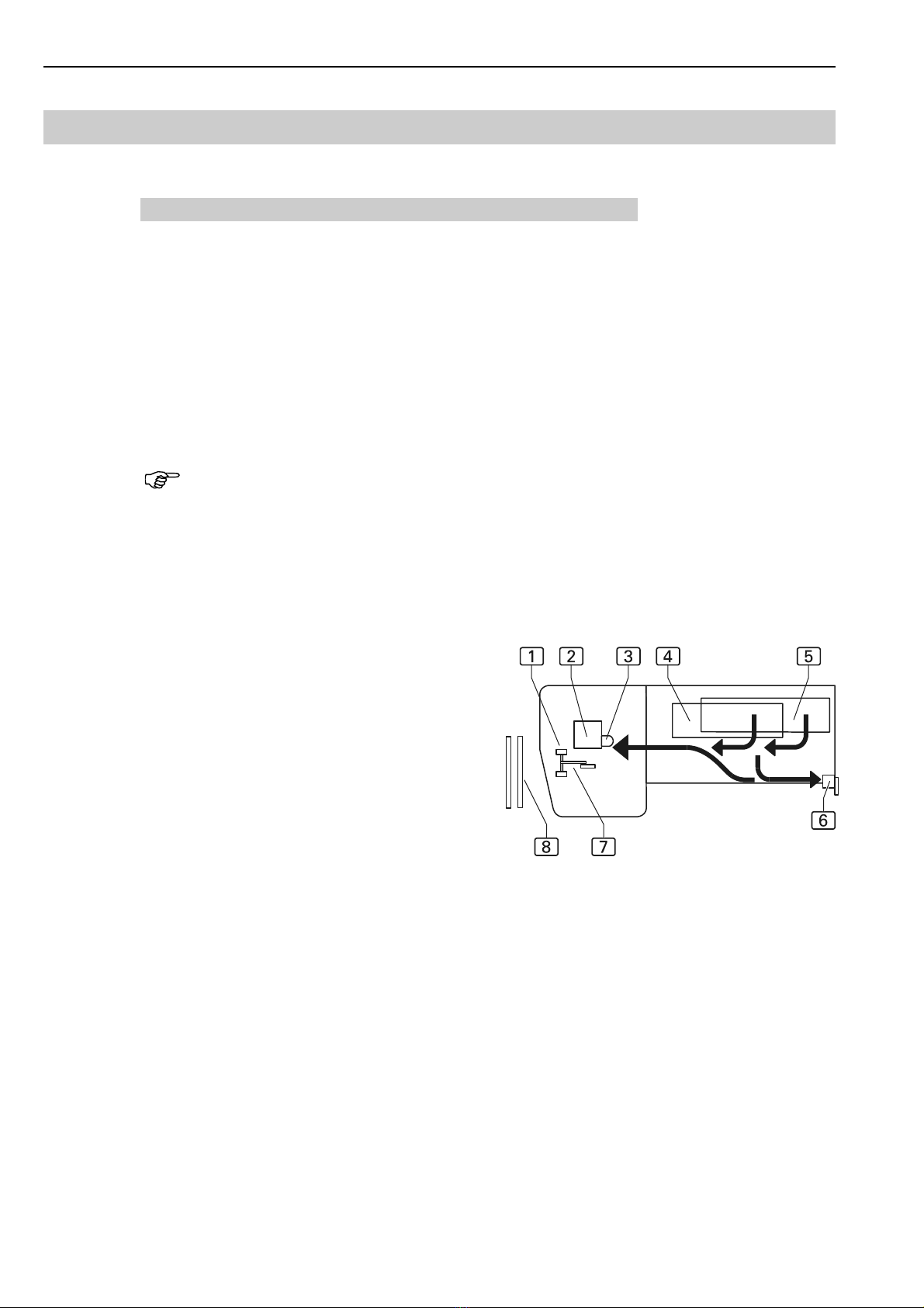
Machine cycle, Fig. 2:
The short seams can be serged manually at the sewing head 2 prior to
the sewing of the inseam or side seam.
The trousers panels are stocked on the upper tray
5, the knee linings are stocked on the lower tray
4. The trousers panel is placed onto the working
plate, the corresponding knee lining is aligned to
the trousers panel with the hems being flush.
At the optional bonding station 6, the front and
rear trousers panels can be secured to each other
using a bonding mesh.
Both trousers panels are routed below the con-
tour guide 3 and lined up at the stop of the se-
wing head 2. A photocell starts the sewing pro-
cess. The fully automatic machine cycle is star-
ted.
During the sewing process, the contour guide 3 and the puller of the
transport unit 7 control the routing of the seam.
If required, the top and bottom transport units of the sewing unit incor-
porate fullness.
The transport unit 7 transports the sewing piece from the working plate
to the stacker 8 where the sewing pieces are stacked on top of each
other.
As soon as the sewing process starts at the sewing head 2, the next
trousers panels can be secured at the bonding station.
Fig. 2

Operating Instructions Automatic Single-Head Serging Machine 1265-4 Beisler Gm H
B-5
B.2 Functions of the machine
B.2.2 Securing the sewing pieces
Bonding station, Fig. 3:
To prevent the trousers panel and the knee lining from being shifted du-
ring the sewing process, they are secured to each other by hot pres-
sing at a lateral location.
At the bonding station 1, a
bonding mesh strip 3 is pla-
ced between knee lining and
trousers panel and heated by
the lower stamp 4 of the
press unit.
Then, the upper stamp 3
and the lower stamp 4
press the sewing pieces to-
gether so that they are secu-
red to each other.
Fig. 3

Operating Instructions Automatic Single-Head Serging Machine 1265-4Beisler Gm H
B-6
B.2 Functions of the machine
B.2.3 uiding of the sewing pieces
The guiding of the sewing pieces along the stop of the sewing head is con-
trolled by the combined action of contour guide and puller.
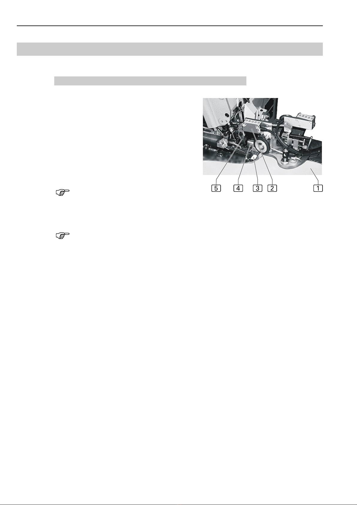
Contour gui e, Fig. 4:
During the transport of trousers pa-
nel and knee lining to the sewing unit,
the contour guide controls the sha-
pe of the fabric contour and ensures
the exact routing of the seam along
the sewing stop 6 of the sewing
unit.
At the contour guide, the following
settings are made for the thickness
of the fabric:
Height quick adjustment 1 of
the contour guide:
Use this control for the rough ad-
justment of the thickness.
The distance between the con-
tour guide sliding shield 4 and
the working plate can be chan-
ged in four stages of 0.8 mm
each in both directions.
Stage 1: smallest distance
(0,8 mm)
Stage 4: largest distance (3.2
mm)
Height fine adjustment 2 of the contour guide:
The rough adjustment made with the height quick adjustment can
be fine-adjusted. The following should be observed as a rule:
A single fabric layer should pass easily below the sliding plate 4
while a double layer must not be allowed to pass through the gap.
The pressure that the contour roller 7 applies to the sewing pie-
ces is set with the adjustment screw 3.
The setting of the compressed-air nozzle 5 that blows the sewing pie-
ces against the stop should not be changed to adjust the contour control.
Stop:
The standard version of the machine has a stop that is secured to the contour
guide.
Optionally, the machine can be equipped with a pneumatic stop.
With this option, a pocket pouch can be inserted between trousers panel
and lining and serged. In this case, the seam section to the end of the pouch
is sewn manually, the remaining section of the seam is sewn fully automa-
tically.
The section that is sewn manually is determined by parameter 10 of the
sewing function STATION CLOSE. At the end of this section, the transport
unit is lowered, the pneumatic stop moves to the pressure foot, and the con-
tour guide controls the seam.
Fig. 4

Operating Instructions Automatic Single-Head Serging Machine 1265-4 Beisler Gm H
B-7
B.2 Functions of the machine
Control, Fig. 5:
The control of the sewing pieces
along the sewing stop is affec-
ted by:
the puller speed 4,
the pressure that the contour
roller 3 applies to the se-
wing pieces.
The photocell 1 determines
the deviation of the fabric con-
tour 2 from the ideal routing at
the reflective film and readjusts
the speed of the puller 4 as re-
quired.
If the sewing pieces are shif-
ted sideways away from the
stop, the puller speed is too
high,
if the sewing pieces warp at
the stop, the puller speed is
too low.
The frequency for adapting the puller speed is set with the program con-
trol.
In addition, the contour roller 3, due to its orientation, pushes the sewing
material toward the stop. The lateral thrust depends on the pressure that
the contour roller applies to the sewing pieces:
If the sewing pieces are shifted sideways away from the stop, the
pressure is too low,
if the sewing pieces warp at the stop, the pressure is too high.
The required contour roller pressure is determined in sewing tests in
combination with the puller speed.
Fig. 5
Operating Instructions Automatic Single-Head Serging Machine 1265-4Beisler Gm H
B-8
B.2 Functions of the machine
B.2.4 Serging the seam
Sewing head, Fig. 6:
The sewing head performs the sewing, thread cut-
ting, and serging functions.
As soon as the photocell 2 recognizes the sewing
pieces 1 (the reflective surface 3 of the photo-
cell is concealed by the sewing piece), the sewing
process starts:
the trousers panel is sewn,
the knife 5 serges the seam,
the thread and fabric residues are aspired into
the waste container.
NOTE - Reflective surfaces
The reflective surface 3 of the photocell must not be damaged or dirty
as otherwise the sewing unit control may be impaired.
NOTE - Cancelling the sewing process
When the program stop switch at the operating panel is depressed, all
machine movements and the sewing process are stopped immediately. The
switch is locked after it has been depressed and must be unlocked for a
reset (machine restart).
Fig. 6

Operating Instructions Automatic Single-Head Serging Machine 1265-4 Beisler Gm H
B-9
B.2 Functions of the machine
B.2.5 Width distribution for knee lining
To ensure the correct width distribution, the transport characteristics of dif-
ferential transport and top transport must be matched to fit the material of
the knee lining.
Presetting, Fig. 7:
In the sewing range of side seam A
and inseam B, the trousers panel
splits into five sections with the knee
lining C extending over four of the-
se sections. For each section, the
length can be varied and the pertai-
ning fullness (quantity) can be preset
with the program control (see Sec-
tion D, Programming Instructions).
Quick a justment, Fig. 8:
The operating panel allows direct
access for the quick adjustment of
the fullness by modifying top transport 2 and differential transport 1.
Select the corresponding function and modify
it in a range between -19 and +19 (see Sec-
tion D, Programming Instructions).
Fig.7
Fig.8

Operating Instructions Automatic Single-Head Serging Machine 1265-4Beisler Gm H
B-10
B.2 Functions of the machine
B.2.6 Transport
Transport unit, Fig. 9:
The transport unit consists of puller 2 and
roller 5.
The puller transports the sewing pieces 4
during the sewing process and uses its
rotational speed to support the control of
the fabric contour.
The roller 5 moves the sewing pieces
beyond the worktable edge and also sup-
ports the transport function of the puller.
This additional transport function can be
enabled for heavy fabrics.
To improve the gliding characteristics of the
trousers panels, the working plate has six com-
pressed-air nozzles 1 in the sewing head
area. The air blows from below against the
trousers panels; the resulting air cushion re-
duces friction during the transport.
In the sewing range of the side seam hip curve, the position of the strut
3 is altered to rotate the trousers panel for the sewing process.
B.2.7 Stacking
Stacker, Fig. 10:
As soon as the chain has been severed and the roller has transported
the sewing pieces beyond the worktable edge, the automatic stacker
is activated and deposits the se-
wing piece 2 over the bundle
rod 1.
Fig. 9
Fig. 10
Table of contents
Other Beisler Industrial Equipment manuals


Popular Industrial Equipment manuals by other brands

Allen-Bradley
Allen-Bradley Guardmaster LRTS installation instructions

TRI tool
TRI tool BEVELMASTER 224B manual

SAMES KREMLIN
SAMES KREMLIN Inorecip V user manual

Donovan
Donovan QUICK-FLIP 4 owner's manual

Nakanishi
Nakanishi RA-100 Operation manual

schmersal
schmersal AZM201Z-CC-T-1P2PW-DU Instructions for operation

Tormach
Tormach Slant-PRO 15L manual

DriSteem
DriSteem Ultra-sorb XV Installation, operation and maintenance manual

Danfoss
Danfoss FIA SS 15-65 installation guide

Reliable
Reliable DDX PrePaK Installation, operation and maintenance manual

OETIKER
OETIKER ELK 02 Series instruction manual

Scotsman
Scotsman Prodigy ELITE A Series Installation and user manual


