BEKA BA337NE User manual

Issue: 7
9th July 2019
BA337NE
Rugged one input
Ex nA and Ex tc
Rate Totaliser
Issue 7

1. Description
2. Operation
2.1 Initialisation
2.2 Controls
2.3 Displays
2.3.1 Display over-range
3. Certification
3.1 ATEX Ex nA certification
3.2 Zones, gas groups & T rating
3.3 Special conditions for safe use
3.4 Power supply
3.5 Pulse input
3.6 Remote reset terminals
3.7 Certification label information
4. System Design for Hazardous Areas
4.1 Power supply
4.2 Pulse input
4.2.1 Input switching thresholds
4.2.2 Switch contact input
4.2.3 Open collector input
4.2.4 2-wire proximity detector input
4.2.5 Magnetic pick-off input
4.2.6 Voltage pulse input
4.3 Remote reset
5. Installation
5.1 Location
5.2 Installation procdedure
5.3 Rate Totaliser earthing
5.4 EMC
5.5 Scale card
6. Configuration and Calibration
6.1 Configuration structure
6.2 Accessing configuration functions
6.3 Summary of configuration functions
6.4 Rate totaliser function: function
6.5 Input: input
6.6 Input type: inp .type
6.7 Debounce: debounce
6.8 Display update interval: update
6.9 Upper display: di5p-1
6.10 Lower display: di5p-2
6.11 Position of decimal points: dp
6.12 Flowmeter K-factor: factor
6.13 Total scale factor: 5cale .t
6.14 Rate scale factor: 5cale .r
6.15 Timebase: t-ba5e
6.16 Display filter: filter
6.17 Clip-off: clp off
6.18 Local reset: loc clr
6.19 Local total reset: clr tot
6.20 Local grand total reset: clr gtot
6.21 Grand total reset from configuration menu:
clr gtot
6.22 Security code: code
6.23 Reset to factory defaults: r5et def
7. Lineariser
7.1 Flowmeter specification
7.2 Summary of lineariser configuration
functions.
7.3 Add a segment: add
7.4 Remove a segment: del
7.5 Input frequency: pul5efre
7.6 K-factors: l-factor
7.7 Lineariser error messages
8. Configuration example
8.1 Configuration procedure
9. Maintenance
9.1 Fault finding during commissioning
9.2 Fault finding after commissioning
9.3 Servicing
9.4 Routine maintenance
9.5 Guarantee
9.6 Customer comments
222222222222222222222222
The BA337NE is CE marked to show compliance with the European Explosive Atmospheres Directive
2014/34/EU and the European EMC Directive 2014/30/EU
CONTENTS

10. Accessories
10.1 Scale card
10.2 Tag information
10.3 Backlight
10.4 Alarms
10.4.1 Solid state output
10.4.2 Ex nA certification
10.4.3 Summary of configuration functions
10.4.4 Alarm enable: enbl
10.4.5 Type of alarm: type
10.4.6 Setpoint adjustment: 5p1x and 5p2x
10.4.7 Alarm function: hi.lo
10.4.8 Alarm output status: no.nc
10.4.9 Hysteresis: h5tr
10.4.10 Alarm delay: dela
10.4.11 Alarm silence time: 5il
10.4.12 Flash display: fl5h
10.4.13 Access setpoint: ac5p
10.4.14 Adjusting alarm setpoints
from totalisation mode:
10.5 Pulse Output
10.5.1 Ex nA certification
10.5.2 Pulse output configuration
10.5.3 Enable pulse output: enbl
10.5.4 Source of pulse output: 5ource
10.5.5 Divide output pulse frequency:
dividE
10.5.6 Output pulse width: duration
10.5.7 Pulse storage
10.6 4/20mA output
10.6.1 Ex nA certification
10.6.2 Configuration
10.6.3 4/20mA output: 4-20op
10.6.4 Enable 4/20mA output:EnbL
10.6.5 Select rate or total source: 4-
20type
10.6.6 Display for 4mA output: 4.000
10.6.7 Display for 20mA output: 20 .000
Appendix 1 Dust certification
Appendix 2 IECEx certification
Appendix 3 ETL and cETL certification
3
CONTENTS CONTINUED

4

1. DESCRIPTION
The BA337NE is an Ex nA and Ex tc certified, panel
mounting, pulse input rate totaliser primarily intended
for use with flowmeters in Zones 2 or 22. The
instrument simultaneously displays the rate of flow
and the total flow in the same or different engineering
units. It is controlled and configured via the four
front panel push buttons, a user defined four digit
code may be entered to prevent accidental access to
the instrument's configuration menu.
This instruction manual supplements the abbreviated
instruction sheet supplied with each instrument.
The BA337NE has been issued with a Type
Examination Certificate ITS16ATEX48409X by
Notified Body Intertek Testing and Certification Ltd.
This confirms compliance with the type of protection
requirements for non-sparking Ex nA apparatus, and
for dust ignition protection by enclosure Ex tc. This
certificate has been used to confirm compliance with
the European ATEX Directive 2014/34/EU.
For international applications the BA337NE also has
IECEx certification which is described in Appendix 2.
For application in the USA or Canada the BA337NE
has ETL and cETL certification, see Appendix 3.
2. OPERATION
Fig 1 shows a simplified block diagram of the
BA337NE Rate Totaliser. The instrument can accept
pulses from most flowmeter transducers. When
connected to a pulse output flowmeter the BA337NE
will provide an accurate display of the rate of flow and
the total flow in the same or different engineering
units. The internal lineariser, which can have up to
sixteen straight-line segments, may be calibrated to
compensate for flowmeter non-linearity.
The BA337NE has a single pair of input terminals 5 &
6 for connection to all types of transducer. When
counting pulses from a transducer requiring
energising, such as a switch contact, open collector
or a two wire proximity detector, an external link
between terminals 3 and 4 supplies power to the
transducer input terminals.
Factory fitted accessories include an internally
powered display backlight and one of three isolated
output options, dual alarms, a pulse or a 4/20mA
output.
Fig 1 BA337NE block diagram
2.1 Initialisation
Each time power is applied to the Rate Totaliser
initialisation is performed. After a short delay the
following display sequence occurs:
All segments of the display are activated
Instrument starts functioning using the
configuration information stored in permanent
memory. Unless total and grand total displays
have been reset to zero, new flow will be
added to the existing totals.
5

2.2 Controls
The BA337NE is controlled and configured via four
front panel push buttons. In the totalisation mode
i.e. when the instrument is displaying rate and total
flow the push button functions are:
Push Button Functions
) + &Grand total - shows Lo followed by least
significant 8 digits of the 16 digit grand
total.
)+ *Grand total - shows Hi followed by the
most significant 8 digits of the 16 digit
grand total.
If Local Grand Total Reset CLr Gtot in
the instrument configuration menu has
been activated, operating the )+ *
buttons for ten seconds will result in
Clr.no being displayed with the no
flashing. Operating the &or *button
will change the display to CLr–.–YE5, the
)button will then reset the grand total
to zero which will be confirmed by a brief
display of Gt Clrd. See 6.20
&+ * If Local Total Reset CLr tot in the
instrument configuration menu has been
activated, operating the &+ *buttons
simultaneously for three seconds will
reset the total display to zero and clear
any pulses stored in the optional pulse
output.
The Grand Total is not reset.
See 6.19
(+ &Shows in succession, firmware version
number, instrument function totali5e
and any output accessories that are
fitted:
- A Dual alarm outputs
- P Pulse output
- C 4/20mA output
( + *Provides direct access to the alarm
setpoints when the Rate Totaliser is
fitted with optional alarms and the AC5P
setpoints function has been enabled.
See 10.4.13 and 10.4.14
(+ )Access to configuration menu
2.3 Displays
The BA337NE has two digital displays and
associated annunciators, plus a flow indicator as
shown on the front cover of this manual.
Total Shows the total flow on the
display upper eight digit display. May
be reset to zero via front panel
push buttons or by a remote
reset switch.
Rate Shows the flow rate on the
Display lower six digit display.
Flow This disc in the lower left
indicator hand corner of the display
'rotates' for two seconds each
time an input pulse is received.
Appears to rotate continuously
when input frequency exceeds
0.5Hz.
Hold Activated when input
annunciator frequency is below the clip-off
threshold.
Reset Activated while instrument is
annunciator being reset via the front panel
push buttons, or the external
reset terminals.
Rate Identifies rate display
annunciator
Total Identifies total display
annunciator
RTx Retransmitted pulse
annunciator annunciator.
Depends upon the setting of
5ource in the pulse output
configuration menu.
5caled:
Annunciator activated each
time pulse output open
collector is on, i.e. Ron is
less than 60+ 3V.
direct:
Annunciator continuously
activated.
2.3.1 Display over-range
Over-range of the upper eight digit display or the
lower six digit display is indicated by all the digits
displaying 9and all the decimal points flashing.
6

3. CERTIFICATION
The BA337NE has ATEX and IECEx Ex nA gas and
Ex tc dust certification. The main sections of this
instruction manual describes ATEX gas certification.
ATEX dust certification is described in Appendix 1
and IECEx gas and dust certification in Appendix 2.
3.1 ATEX Ex nA certification
Notified Body Intertek Testing and Certification Ltd
have issued the BA337NE with a Type Examination
Certificate number ITS16ATEX48409X. This has
been used to confirm compliance with the European
ATEX Directive for Group II, Category 3G equipment.
The instrument carries the Community Mark and,
subject to local codes of practice, may be installed in
any of the European Economic Area (EEA) member
countries and in the EEA EFTA states, Iceland,
Liechtenstein and Norway. ATEX certificates are also
acceptable in Switzerland and Turkey. The
European Commission's Blue Guide lists the member
states, overseas countries and territories that have
adopted harmonisation legislation.
This section of the instruction manual describes
ATEX installations in explosive gas atmospheres
conforming with EN 60079-14 Electrical installations
design, selection and erection. When designing
systems for installation outside the UK the local Code
of Practice should be consulted.
3.2 Zones, gas groups and T rating
The Rate Totaliser has been certified as Group II
Category 3G Ex ic nA IIC T5 Gc –40°C Ta +60°C
apparatus. This is non-sparking apparatus complying
with EN 60079-15 Equipment protection by type of
protection 'n' that minimises the risk of arcs or sparks
capable of creating an ignition hazard occurring
during conditions of normal operation.
The Rate Totaliser's front panel push button contacts
are non incendive and have been certified intrinsically
safe Ex ic without an external Zener barrier or
galvanic isolator, as shown on the Type Examination
Certificate. This allows the Rate Totaliser to be
adjusted and configured live when installed in a Ex n
panel enclosure located in Zones 2.
When connected to a suitable system and correctly
mounted in a panel enclosure complying with the
requirements for Type of protection 'n', the panel
enclosure containing the BA337NE Rate Totaliser
may be installed in:
Zone 2 explosive gas air mixture not
likely to occur, and if it does
will only exist for a short time.
Be used with gases in groups:
Group A propane
Group B ethylene
Group C hydrogen
In gases that may safely be used with equipment
having a temperature classification of:
T1 450oC
T2 300oC
T3 200oC
T4 135oC
T5 100oC
At ambient temperatures between -40 and +60oC.
This allows use with all commonly used industrial
gases except carbon disulphide CS2.
3.3 Special conditions for safe use
Special conditions for safe use are specified by the
Ex nA certificate indicated by the certificate number's
'X' suffix. These state that the BA337NE Rate
Totaliser should be:
a. Mounted such that the instrument terminals are
protected by at least an IP54 enclosure
certified to IEC 60079-0 or IEC 60079-15 as
appropriate.
b. Be supplied from limited energy circuits with
output parameters in normal operation equal
to, or less than the instruments input
parameters.
These special conditions for safe use can be satisfied
by mounting the BA337NE in an Ex n, Ex e or Ex p
panel enclosure. For ATEX Category 3 installations
in Zone 2, self or third party certified Ex n, Ex e or
Ex p panel enclosures may be used. Additional
requirement apply for non-metallic panel enclosures.
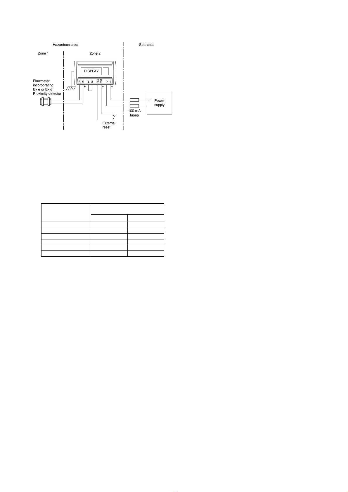
3.4 Power supply
The input safety parameters for the power supply
terminals 1 and 2 are:
Ui = 30dc
Ii = 100mA
This allows the BA337NE to be powered from any dc
supply which in normal operation has an output
voltage of less than 30V. See section 4.1 for power
supply recommendations.
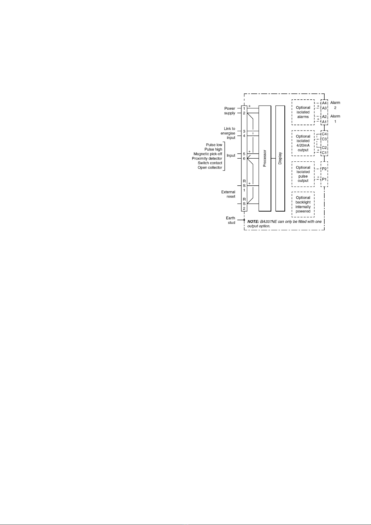
3.5 Pulse input
The BA337NE Rate Totalisers has a single pair of
pulse input terminals 5 and 6 that may be configured
for use with different types of sensor.
For sensors that require energising to determine their
state, such as switch contacts or a 2-wire proximity
detector, an external link between terminals 3 & 4 of
the BA337NE connects an internal 7V, 6mA supply to
the input terminals.
7

Energising is not required when the Rate Totaliser
input is connected to a voltage pulse source.
Fitting an external link between terminals 3 & 4
changes the Rate Totaliser's pulse input safety
parameters in normal operation as shown below.
This table also shows the types of sensor requiring
energising (link fitting).
Safety parameters
Input Output
Type of input Link 3 & 4 Ui Uo Io
Switch contact Yes 15V 10.5V 9.2mA
Proximity detector Yes 15V 10.5V 9.2mA
Open collector Yes 15V 10.5V 9.2mA
Magnetic pick-off No 30V 1.1V 0.5mA
Voltage input (low) No 30V 1.1V 0.5mA
Voltage input (high) No 30V 1.1V 0.5mA
3.6 Remote reset terminals
The BA337NE total display my be reset to zero by
connecting the external reset terminals RS1 and RS2
together for more than one second. The two reset
terminals have the following safety parameters in
normal operation:
Ui = 30V
Uo = 3.8V
Io = 1mA
3.7 Certification label information
The Rate Totaliser certification information label is
fitted in a recess on the top outer surface of the
enclosure. It shows the ATEX and IECEx certification
information plus BEKA associates name, location,
year of manufacture and the instrument serial
number.
BA337NE Certification information label
4. SYSTEM DESIGN FOR HAZARDOUS AREAS
When correctly installed in Zone 2 the BA337NE
Rate Totaliser may be connected to almost any
apparatus in the safe area and to Ex n, Ex e, Ex p
and Ex d protected apparatus located in Zone 2.
Because the BA337NE is not certified intrinsically
safe it should not be connected to an intrinsically safe
system.
BEKA Application Guide AG310, Guide for
Installation of [extra low voltage d.c.] Ex nA
instrumentation, which can be downloaded from
www.beka.co.uk, contains explanations and
recommendations for the installation of Ex nA
equipment.
In addition to being able to be connected to other
equipment in the safe area and in Zone 2, the
BA337NE may also be connected to suitably
protected and certified equipment located in Zone 1.
This is illustrated in Fig 5 and explained in
Application Guide AG310.
There are four design requirements:
1. The BA337NE must be installed in a panel
enclosure complying with the requirements for
Ex n protection as shown in section 5 of this
manual.
2. The BA337NE should be powered from a
circuit that has output safety parameters in
normal operation equal to, or less than, the
input safety parameters for terminals 1 and
2 specified by the BA337NE ATEX Type
Examination Certificate.
3. Hazardous area apparatus to which the
BA337NE is connected should be protected
by a technique suitable for the Zone in
which the equipment is located such as Ex n
or Ex e if located in Zone 2. Equipment
protected by intrinsic safety should not be
connected to a BA337NE.
4. Wiring should comply with Clause 9 of
EN 60079-14.
When designing a system it is important to remember
that terminals 2, 6 and RS2 are interconnected within
the BA337NE. See Fig 1.
4.1 Power supply
The BA337NE Rate Totaliser require a minimum of
10V between terminal 1 & 2 and consumes:
10mA without optional backlight
plus 6mA when terminals 3 & 4 are linked
A 24V dc regulated supply with a current limit located
in a safe area is suitable.
8

The power supply should meet the requirements for
personnel safety so that ‘live maintenance’ can safely
be performed. The implicit requirement for galvanic
isolation from the mains supply ensures that the
possible difficulties from circulating earth currents
caused by mains faults is minimised. In European
terms if the power supply is CE marked it is almost
certainly acceptable.
To comply with the requirements of EN 60079:14
Electrical installations design, selection and erection,
each of the wires entering the hazardous area should
be individually fused and contain a means of
isolation. These two requirements may be satisfied
by using DIN rail mounted terminals incorporating a
fuse with easily removable fuses which can be
extracted to achieve isolation as shown in Fig 2.
Clear identification of, and easy access to the means
of isolation is essential for their effective use. It is
also necessary to ensure that the maintenance
procedure makes sure that unauthorised re-closure
of the switches does not occur. It is not considered
necessary to have a means of isolation or electrical
protection for the screen.
Fig 2 DIN rail mounting terminals incorporating a
fuse
For some applications Ex nA instrumentation
energised by a current limited power supply or
instrument that can be switched off, is considered
adequate and to comply with the requirements of the
standard.
4.2 Pulse input
The BA337NE can display the rate and total flow
from flowmeters with a wide variety of pulse outputs
located in a Zone 2 hazardous areas or in a safe
area. Fig 3 shows the connections when the
flowmeter is located in Zone 2 and Fig 4 the
connections required when the flowmeter is in a safe
area.
Fig 3 Connections for flowmeter sensor in Zone 2
Fig 4 Connections for flowmeter sensor in safe area
Providing the BA337NE Rate Totaliser is correctly
installed in an Ex n panel enclosure located in Zone
2, the input terminals may be connected to a certified
flowmeter sensor located in Zone 1 as shown in Fig
5. The flowmeter sensor should have Ex e or Ex d
certification permitting installation in Zone 1.
Intrinsically safe Ex i certified flowmeter sensors
should not be used.
9

Fig 5 Connection to an Ex d or Ex e flowmeter in
Zone 1
4.2.1 Input switching thresholds
For reliable totalisation the Rate Totaliser pulse input
must fall below the lower threshold and rise above
the upper thresholds shown in the following table.
Input transducer
Switching thresholds
Lower Upper
Open collector 2k10k
Voltage pulse low 1.0V 3.0V
Voltage pulse high 3.0V 10.0V
Magnetic pick-off 0mV 40mV peak
Proximity detector 1.2mA 2.1mA
Switch 1001000
Flowmeters with a switch contact, proximity detector
or an open collector output require energising which
is achieved by linking Rate Totaliser terminals 3 & 4.
4.2.2 Switch contact input
Any flowmeter with a mechanically or magnetically
activated switch contact located in Zone 2 or in the
safe area may be directly connected to pulse input
terminals 5 and 6 which are non incendive, providing
the flowmeter and associated wiring can withstand a
500V rms insulation test to earth. Most magnetically
activated reed relays used in turbine flowmeters
comply with these requirements. The BA337NE
contains a configurable debounce circuit to prevent
contact bounce being counted. See section 6.7.
4.2.3 Open collector input
Flowmeters with an open collector output located in
Zone 2 or in the safe area may be directly connected
to input terminals 5 & 6 providing the flowmeter and
associated wiring can withstand a 500V rms
insulation test to earth.
The BA337NE contain a configurable debounce
circuit to prevent false triggering. See section 6.7.
4.2.4 2-wire proximity detector input
Most Zone 2 certified flowmeters incorporating a
NAMUR 2-wire proximity detector may be directly
connected to a BA337NE input terminals 5 & 6
providing minimum operating voltage is greater than
7.5V. The flowmeter and the associated wiring
should be able to withstand a 500V rms insulation
test to earth.
The BA337NE contain a configurable debounce
circuit to prevent false triggering. See section 6.7.
4.2.5 Magnetic pick-off input
Flowmeters incorporating a magnetic pick-off to
sense flow will usually have a low level ac voltage
output which a BA337NE Rate Totaliser can sense
when configured for a CoiL input. The Rate Totaliser
input terminals 5 and 6 may be connected to any
Zone 2 certified magnetic pick-off output flowmeter,
providing the output in normal operation is equal to or
less than 30V the Rate Totaliser's Ui. The flowmeter
and associated wiring should be able to withstand a
500V rms insulation test to earth.
The BA337NE contain a configurable debounce
circuit to prevent false triggering. See section 6.7.
4.2.6 Voltage pulse input
Two voltage pulse input ranges are selectable in the
BA337NE Rate Totaliser configuration menu, VoLt5
Land VoLt5 H. The Rate Totaliser input terminals 5
and 6 may be connected to any Zone 2 certified
voltage pulse output flowmeter, providing the output
in normal operation is equal to or less than 30V the
Rate Totaliser's Ui. The flowmeter and associated
wiring should be able to withstand a 500V rms
insulation test to earth.
The BA337NE contain a configurable debounce
circuit to prevent false triggering. See section 6.7.
4.3 Remote reset
The BA337NE Rate Totaliser's total display may be
remotely reset to zero by connecting terminals RS1
and RS2 together. Permanent interconnection
inhibits totalisation. Remote resetting may be
accomplished by any mechanically operated switch
located in Zone 2 as the Rate Totaliser's reset circuit
is non incendive. The reset switch and the
associated wiring should be able to withstand a 500V
rms insulation test to earth.
A BA337NE may also be remotely reset from the safe
area. Any switch may be used. Fig 4 illustrates how
a BA337NE may be reset from both the safe and the
hazardous area.
The BA337NE total display may also be reset when
the &and *push buttons are operated
simultaneously in the totalising mode i.e. when the
instrument is displaying flow. See 6.19
10

5. INSTALLATION
5.1 Location
When installed in a panel enclosure complying with
the requirements for Ex n protection as shown in
section 3.2 of this manual, the BA337NE may be
located in a Zone 2 hazardous area providing that the
operating temperature is between –40°C and +60°C
and the installation complies with the Rate Totalisers
certification requirements. Certified Ex e panel
enclosures are frequently used as Ex n panel
enclosures.
The BA337NE Rate Totaliser has a stainless steel
housings with a 7J front of panel impact resistance
incorporating a 10mm thick toughened glass window
which can withstand a 4J impact. This, together with
a captive silicone gasket which seals the joint
between the instrument and the panel, enclosure
provides IP66 ingress protection. The BA337NE has
IP20 rear protection.
Although the front of the BA337NE Rate Totaliser has
IP66 protection, it should be shielded from
continuous direct sunlight and severe weather
conditions.
Fig 6 shows the overall dimensions of the BA337NE
together with the recommended panel enclosure cut-
out dimensions.
5.2 Installation Procedure
a.Cut the aperture specified in Fig 6 in the panel
enclosure. Ensure that the edges of aperture are
de-burred.
b.Inspect the Rate Totaliser's captive gasket and
ensure that it is not damaged before inserting it into
the panel enclosure aperture.
c.If the enclosure panel is less than 1.0mm thick, or
is non-metallic, an optional BEKA stainless steel
support plate should be slid over the rear of the
indicator before the panel clamps are fitted to
evenly distribute the clamping force and prevent the
enclosure panel being distorted or creeping.
d.Slide a panel clamp into the two grooves at each
corner of the indicator housing with the M3 stud
protruding through the hole at the rear of the clamp.
Fit the stainless steel spring washer over the stud
and secure with the stainless steel wing nut.
e.Evenly tighten the four clamps to secure the
instrument. The recommended minimum tightening
torque for each wing nut is 22cNm (1.95 lbf in).
f. Connect the panel enclosure wiring to the rear
terminal blocks. To simplify installation, the
terminals are removable so that wiring can be
completed before the instrument is installed.
Wiring should be supported to prevent damage
resulting from vibration.
g.Finally, fit a silicone rubber push-on cap to the end
of each M3 threaded rod.
Support panel wiring to prevent vibration damage
Note: Optional backlight is internally powered
Fig 6 BA337NE dimensions and terminals
11

Fig 7 Installation procedure
5.3 Rate totaliser earthing
The BA337NE has an M4 earth stud on the rear
panel which should be electrically connected to the
panel enclosure in which the Rate Totaliser is
mounted, or to the plant equipotential conductor.
5.4 EMC
The BA337NE complies with the requirements of the
European EMC Directive 2014/30/EU. For specified
immunity all wiring should be in screened twisted
pairs, with the screens earthed in the safe area.
Fig 8 Rear terminals
5.5 Scale card
The Rate Totaliser's units of measurement are shown
on a printed scale card in a window at the right hand
side of the display. The scale card is mounted on a
flexible strip that is inserted into a slot at the rear of
the instrument as shown in Fig 9. Thus the scale
card can easily be changed without dismantling the
indicator or removing it from the Ex n enclosure in
which it is mounted.
New Rate Totalisers are supplied with a printed scale
card showing the requested units of measurement, if
this information is not supplied when the instrument is
ordered a blank card will be fitted.
A pack of self-adhesive scale cards printed with
common units of measurement is available as an
accessory from BEKA associates. Custom printed
scale cards can also be supplied.
To change a scale card, unclip the protruding end of
the flexible strip by gently pushing it upwards and
pulling it out of the enclosure. Peel the existing
scale card from the flexible strip and replace it with a
new printed card, which should be aligned as shown
below. Do not fit a new scale card on top of an
existing card.
Install the new scale card by gently pushing the
flexible strip into the slot at the rear of the Rate
Totaliser, when it reaches the internal end-stop
secure it by pushing the end of the flexible strip
downwards so that the tapered section is held by the
Rate Totaliser rear panel.
Align the self-adhesive printed
scale card onto the flexible strip
and insert the strip into the
indicator as shown below.
Fig 9 Inserting flexible strip carrying scale card
into slot at the rear of indicator.
12

6.0 CONFIGURATION & CALIBRATION
The BA337NE Rate Totalisers is configured and
calibrated via four front panel push buttons. All the
configuration functions are contained in an easy to
use intuitive menu that is shown diagrammatically in
Fig 11.
Each menu function is summarised in section 6.3 of
this manual and each summary includes a reference
to more detailed information. The sixteen segment
lineariser is described separately in section 7.
Configuration of the optional isolated pulse output,
optional alarms and the optional 4/20mA output are
described separately in section 10. When fitted they
appear as additional functions within the
configuration menu.
All new Rate Totalisers are supplied calibrated as
requested at the time of ordering. If calibration is not
requested, Rate Totalisers will have default
configuration as shown in the following table, but can
easily be re-configured on-site.
Function Display Default
Access code CodE 0000
Function FunCtion 5td
Input inP .tYPE oP .CoL
Debounce dEbounCE dEFAuLt
Update uPdAtE 0 .5
Upper display di5p-1 totAL
Lower display di5P-2 on
Decimal point dP Rate 0.0
Total 0
K Factor FACtor 1 .0
Total scale factor 5CALE .t1.0
Rate scale factor 5CALE .r1.0
Timebase t-bA5E 5EC
Filter FiLter 24
Clip-off CLP-oFF 0
Local total reset t-rE5Et oFF
Local grand total reset Gt-rE5Et oFF
Security code CodE 0000
Note: While the instrument is being configured
totalisation continues so that any flow occurring
during this time is recorded.
6.1 Calibration structure
Fig 10 shows the BA337NE calibration structure.
The rate and total display calibrations are
independent which allows the displays to have
different engineering units.
The rate totaliser pulse input is divided by FACtor
which is usually set to the K-factor of the flowmeter,
thus converting the flowmeter output into engineering
units. When the 16 segment lineariser Lin is
selected in the Function sub-menu, up to 16 values
for FACtor may be entered each at a specified input
pulse frequency to compensate for flowmeter
nonlinearity. See section 7.
5CALE-r is a dividing factor that converts the output
from FACtor into the required rate display in
engineering units. e.g. if the output from FACtor is
one pulse per litre and the rate display is required in
gallons, 5CALE-r should be set to 4.5461 which is the
number of litres in an imperial gallon.
The timebase t-bA5E is a multiplying factor that
determines if the instrument displays flow per
second, per minute or per hour.
The total flow display is independent of the rate
display. 5CALE-t is a dividing factor that converts the
output from FACtor into the required total display
engineering units. e.g. if the output from FACtor is
one pulse per litre and the total display is required in
thousands of gallons, 5CALE-t should be set to
4,546 .1which is the number of litres in 1,000 imperial
gallons.
The BA337NE uses ‘real’ decimal points. Moving the
position of a decimal point in a scale factor will affect
the instrument calibration.
Fig 10 Calibration structure
13

6.2 Accessing configuration functions
Throughout this manual push buttons are shown as
&, *, (and )and legends displayed by the
instrument are shown in a seven segment font
exactly as they appear on the instrument display e.g.
inPut and uPdAtE.
Access to the configuration menu is obtained by
operating the (and )push buttons
simultaneously. If the instrument is not protected by
a security code the first parameter FunCtion will be
displayed. If a security code other than the default
code 0000 has already been entered, the instrument
will display CodE. Press (to clear this prompt and
enter the security code for the instrument using the
&or *push button to adjust each digit, and the
(push button to transfer control to the next digit. If
the correct code has been entered pressing )will
cause the first parameter FunCtion to be displayed.
If an incorrect code is entered, or a push button is not
operated within ten seconds, the instrument will
automatically return to the totalisation mode.
All configuration functions and prompts are shown on
the upper eight digit display.
Once within the main configuration menu the required
parameter can be selected by scrolling through the
menu using the &or *push button. The
configuration menu is shown diagrammatically in
Fig 11.
When returning to the totalisation mode following
reconfiguration, the Rate Totaliser will display dAtA
followed by 5AVE while the new information is stored
in permanent memory.
6.3 Summary of configuration functions
This section summarises all the configuration
functions. When read in conjunction with Fig 11 it
provides a quick aid for configuring the Rate Totaliser.
If more detail is required, each section contains a
reference to a full description of the function.
Display Summary of function
FunCtion Rate Totaliser function
Defines the relationship between the
pulse input and the Rate Totaliser
display. May be set to:
5td Standard linear relationship
Lin 16 segment adjustable
lineariser - see section 7.
See section 6.4
inPut Input
Contains sub-menu with two
functions
inP .tYPE Select Input type
dEbounCE Set debounce
See section 6.5
inP .tYPE
Configures the Rate Totaliser to
accept one of six types of input:
oP,CoL Open collector *
VoLt5 L Voltage pulse <1 >3V
VoLt5 H Voltage pulse <3 >10V
CoiL Magnetic pick-off
Pr .dEt Proximity detector *
ContACt Switch contact *
*Link terminals 3 & 4
See section 6.6
dEbounCE
Defines level of input debounce
applied to the pulse input to prevent
false counting:
dEFAuLt
HEAVY
LiGHt
See section 6.7
UpdAtE Display update interval
Define the interval between display
updates between 0.5 and 5 seconds.
See section 6.8
14

Display Summary of function
di5P-1 Upper display
Defines whether rAtE or totAL is
shown on the upper display. The
other variable will be shown on the
lower display, providing the lower
display is on in function dI5P-2.
See section 6.9
di5P-2 Lower display
Turns the lower display, which
normally shows rate, on or oFF.
See section 6.10
dP Decimal points
Defines the position of the decimal
point in both the rate and total
displays.
See section 6.11
FACtor Flowmeter K-factor
The rate totaliser pulse input is
divided by FACtor, which is usually
set to the K-factor of the flowmeter,
thus converting the flowmeter output
into engineering units. FACtor may
be adjusted between 0.0001 and
99999.
When the 16 segment lineariser Lin
is selected in the Function sub-menu,
up to 16 values for FACtor may be
entered, each at a specified input
pulse frequency to compensate for
flowmeter non-linearity.
See section 6.12
5CALE.t Total Scale Factor
5CALE-t is a dividing factor that
converts the pulse output from
FACtor into the required total display
in engineering units. e.g. if the
output from FACtor is one pulse per
litre and the total display is required
in thousands of gallons, 5CALE-t
should be set to 4546 .1 which is the
number of litres in 1,000 imperial
gallons.
5CALE-t may be adjusted between.
0.0001 and 99999.
The total flow display is independent
of the rate display.
See section 6.13
Display Summary of function
5CALE.r Rate scale factor
5CALE .ris a dividing factor that
converts the pulse output from
FACtor into the required rate display
in engineering units. e.g. if the
output from FACtor is one pulse per
litre and the rate display is required in
gallons, 5CALE .rshould be set to 4.
5461 which is the number of litres in
an imperial gallon.
5CALE .rmay be adjusted between
0.0001 and 99999. The flow rate
display is independent of the total
flow display.
See section 6.14
t-bA5E Timebase
Selectable multiplier allowing flow
rate to be displayed in units per
second, per minute or per hour.
Select:
tb-01 for flow / second
tb-60 for flow / minute
tb-3600 for flow / hour
See section 6.15
FiLtEr Display filter
An adjustable digital filter to reduce
noise on the rate display is controlled
by two parameters each adjustable
between 0and 9. The first digit
defines the amount of filtering applied
to the display, the second deviation
from the displayed rate at which the
filter will be overridden and the rate
display will move rapidly to the new
value.
See section 6.16
CLP-oFF Clip-off
To prevent totalisation of very low
flow rates, clip-off enables the user to
select a flow rate display below which
totalisation is inhibited.
See section 6.17
15

Display Summary of function
LoC Clr Local reset
Contains sub-menu with two
functions enabling total and grand
total to be reset to zero via the front
panel push buttons when the Rate
Totaliser is in the totalisation mode.
See section 6.18
Local total reset Clr tot
When on is selected total display is
reset when &and *buttons are
operated simultaneously for more
than 3 seconds in the operating
mode.
See section 6.19
Local grand total reset clr gtot
When on is selected the grand total is
reset when )+ *buttons are
operated simultaneously for more
than 10 seconds in the operating
mode.
Note: Once reset, the grand total
can not be restored.
See section 6.20
Display Summary of function
CLr-Gtot Reset grand total from
configuration menu.
This function resets the grand total to
zero from within the configuration
menu when CLr YE5 is selected, and
5urE is entered to confirm the
instruction.
Note: Once reset, the grand total can
not be recovered.
See section 6.21
CodE Security code
Defines a four digit alphanumeric
code which must be entered to gain
access to the configuration menu.
Default code 0000 disables the
security function and allows
unrestricted access to all
configuration functions.
See section 6.22
r5Et def Reset to factory defaults
Returns the Rate Totaliser
configuration functions to the factory
default shown in section 6. To
prevent accidental use the request
must be confirmed by entering 5urE
before the reset will be executed.
See section 6.23
16

6.4 Rate Totaliser function: FunCtion
The Rate Totaliser contains an adjustable sixteen
segment lineariser which may be used to
compensate for flowmeter non-linearity. This
function turns the lineariser on or off.
5td Lineariser not activated
Lin Lineariser activated
To reveal the existing Rate Totaliser function select
FunCtion from the configuration menu and press (.
If the function is set as required, press )to return to
the configuration menu, or press the &or *button
to change the setting, followed by the )button to
return to the FunCtion prompt in the configuration
menu.
5td Linear
Provides a linear relationship between the
pulse input and the Rate Totaliser displays.
Lin 16 segment adjustable lineariser
Enables a sixteen segment adjustable
lineariser. When Lin is selected the FACtor
function is expanded to allow up to 16 values
to be entered for different input pulse
frequencies. Detailed information about the
lineariser including configuration is contained
in section 7 of this instruction manual.
6.5 Input: inPut
The Input function contains two sub-functions
inP .tYPE and dEbounCE which configure the Rate
Totaliser input and input noise rejection.
6.6 Input type: inP .tYPE
inP .tYPE is a sub-menu in the inPut function which
defines the type of flowmeter or input pulse that the
Rate Totaliser will count. To check or change the
type of input, select inPut in the main configuration
menu and press (which will reveal the inP .tYPE
prompt, pressing (again will show the Rate
To t al i s er i n p u t . If set as required press )twice to
return to the configuration menu, or repeatedly press
the &or *button until the required type of input is
displayed, then press )twice to return to the
configuration menu.
One of following six types of input may be selected:
Switching
thresholds
Low High
oP,CoL Open collector 2210k
VoLt5 L Voltage pulse low 113V
VoLt5 H Voltage pulse high 1310V
CoiL Magnetic pick-off 1040mV
Pr .dEt Proximity detector 21.2 2.1mA
ContACt Switch contact 2100 1000
Notes:
1. Maximum voltage input +30V.
2. For flowmeter transducers that require
energising i.e. proximity detectors, switch
contacts or open collectors, terminals 3 & 4 of
the Rate Totaliser should be linked together.
3. To count correctly, the input pulse must fall
below the lower switching threshold and rise
above the higher switching threshold.
4. See section 6.7 for maximum counting
frequency.
17

18

19

6.7 Debounce: dEbouncE
dEbouncE is an adjustable sub-menu in the inPut
function which prevents the Rate Totaliser
miscounting when the input pulse has noisy edges,
such as those resulting from a mechanical contact
closing and bouncing. Three levels of protection may
be selected and the amount of debounce applied
depends upon the type of Rate Totaliser input that
has been selected in the inP .tYPE function.
The following table shows the minimum time that the
input pulse must be continuously above the upper
input switching threshold and continuously below the
lower switching threshold to ensure that the Rate
Totaliser processes the input pulse. Input switching
thresholds are shown in section 4.2.1.
De-bounce
level
Min input pulse width
Type of Input
Contact All others
Default 1600µs 40µs
Heavy 3200µs 350µs
Light 400µs 5µs
The Rate Totaliser’s maximum counting frequency
depends upon the debounce level selected, the
shape of the input pulse and its amplitude. The
following table assumes a square wave input and is
only for guidance. The maximum counting frequency
will be lower if the input pulses have sloping edges
and the pulse amplitude only slightly exceeds the
input switching thresholds.
ONLY FOR GUIDANCE
De-bounce
level
Max counting frequency
Type of input
Contact All others
Default 250Hz 12kHz
Heavy 120Hz 2kHz
Light 1000Hz 100kHz
The minimum input frequency is 0.01Hz. Below this
frequency the rate display will be forced to zero.
The dEbouncE function is a sub-menu located in the
inPut function. Select inPut in the configuration
menu and press (which will reveal the inP .tYPE
prompt, press the &or *button to select dEbouncE
followed by (to reveal the existing setting.
Pressing the &or *button will scroll through the
three levels. When the required level has been
selected, pressing )twice will enter the selection
and return the display to the inPut prompt in the
configuration menu.
6.8 Display update interval: uPdAtE
If either the rate or the total display is likely to change
rapidly, a longer interval between display updates
may simplify reading the Rate Totaliser display. This
function allows one of six different display intervals
between 0.5 and 5 seconds to be selected. The
selected display update interval does not affect the
update time of any other instrument function.
To adjust the update interval select uPdAtE from the
configuration menu and press (to reveal the
existing time. Pressing the &or *button will
scroll through the six times. When the required
interval has been selected press )to enter the
selection and return to the configuration menu.
6.9 Upper display: di5P-1
Usually total flow is shown on the larger upper eight
digit display, but this function allows rate to be shown
on the upper display and total on the smaller lower
display which can show six positive digits.
To check the status of the upper display, select dI5P-
1from the configuration menu and press (which
will reveal if the display is showing rAtE or totAL.
The setting can be changed by pressing the &or
*button followed by the ) button to enter the
selection and return to the configuration menu.
6.10 Lower display: di5P-2
This function turns the lower display on or off. When
turned off the BA337NE will only have one eight digit
display which may be configured in the di5P-1
function to show total flow or rate of flow.
To check the status of the lower display, select di5P-
2from the configuration menu and press (to reveal
if the lower display is on or oFF. The setting may be
changed by pressing the &or *button followed by
the )button to enter the selection and return to the
configuration menu.
20
Table of contents
Other BEKA Control Unit manuals
Popular Control Unit manuals by other brands

Task Force Tips
Task Force Tips METRO 0 Series Instruction for operation and maintenance

Trenz Electronic
Trenz Electronic TE0712 TRM manual

Flowserve
Flowserve R6 Installation, operation and maintenance instructions

HORNER APG
HORNER APG HE-XPBS Specifications & installation

KSB
KSB Controlmatic E.2 manual

Texas Instruments
Texas Instruments TLC694 Series Technical reference manual