6
When connected to a suitable system and correctly
mounted in a panel enclosure complying with the
requirements for Type of protection 'n', the panel
enclosure containing the BA377NE may be installed
in:
Zone 2 explosive gas air mixture not
likely to occur, and if it does
will only exist for a short time.
Be used with gases in groups:
Group A propane
Group B ethylene
Group C hydrogen
In gases that may safely be used with equipment
having a temperature classification of:
T1 450oC
T2 300oC
T3 200oC
T4 135oC
T5 100oC
At ambient temperatures between -40 and +60oC.
This allows use with all commonly used industrial
gases except carbon disulphide CS2.
2.3 Special conditions for safe use
Special conditions for safe use are specified by the
Ex nA certificate indicated by the certificate
number's 'X' suffix. These state that the BA377NE
Timer or Clock should be:
a. Mounted such that the instrument terminals
are protected by at least an IP54 enclosure
compliant with IEC 60079-0 & IEC 60079-15.
b. Be supplied from limited energy circuits with
output parameters in normal operation equal
to, or less than the instruments input
parameters.
These special conditions for safe use can be
satisfied by mounting the BA377NE in an Ex n, Ex e
or Ex p panel enclosure. For ATEX Category 3
installations in Zone 2, self or third party certified
Ex n, Ex e or Ex p panel enclosures may be used.
Additional requirement apply for non-metallic panel
enclosures.
2.4 Power supply
The input safety parameters for the power supply
terminals 1 and 2 are:
Ui = 30V dc
Ii = 100mA
This allows the BA377NE to be powered from any
dc supply which in normal operation has an output
voltage of less than 30V. See section 3.1 for power
supply recommendations.
2.5 Input terminals
The BA377NE Timer or Clock has a single pair of
pulse input terminals 5 and 6 that may be configured
for use with different types of sensor.
For sensors that require energising to determine
their state, such as switch contacts or a 2-wire
proximity detector, an external link between
terminals 3 & 4 of the BA377NE connects an internal
7V, 6mA supply to the input terminals. Energising is
not required when the Timer or Clock input is
connected to a voltage pulse source.
Fitting an external link between terminals 3 & 4
changes the Timer or Clock's pulse input safety
parameters as shown below. This table also shows
the types of sensor requiring energising (link fitting).
Safety parameters
Input Output
Type of input Link 3 & 4 Ui Uo Io
Switch contact Yes 15V 10.5V 9.2mA
Proximity detector Yes 15V 10.5V 9.2mA
Open collector Yes 15V 10.5V 9.2mA
Magnetic pick-off No 30V 1.1V 0.5mA
Voltage input (low) No 30V 1.1V 0.5mA
Voltage input (high) No 30V 1.1V 0.5mA
2.6 Remote reset terminals
The BA377NE total display my be reset to zero by
connecting the external reset terminals RS1 and
RS2 together for more than one second. The two
reset terminals have the following safety parameters
in normal operation:
Ui = 30V
Uo = 3.8V
Io = 1mA
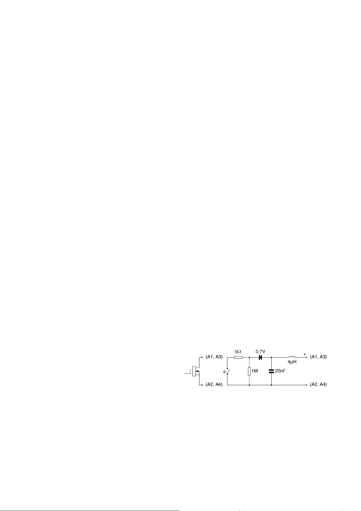
2.7 Control outputs - optional
Each of the two optional control outputs is a
separate galvanically isolated Ex nA circuit with the
following input parameters:
Ui = 30V dc
Ii = 200mA
This allows each control output to switch any dc
circuit providing that in normal operation the
maximum supply voltage is not greater than 30V dc
and the switched current is not greater than 200mA.
Providing that the BA377NE Timer or Clock is
correctly installed in a panel enclosure located in
Zone 2 complying with the requirements for Ex n
protection, the two control outputs may be used to
switch suitably protected equipment located in Zone
1 or 2 of a hazardous area, or equipment located in
a safe area.