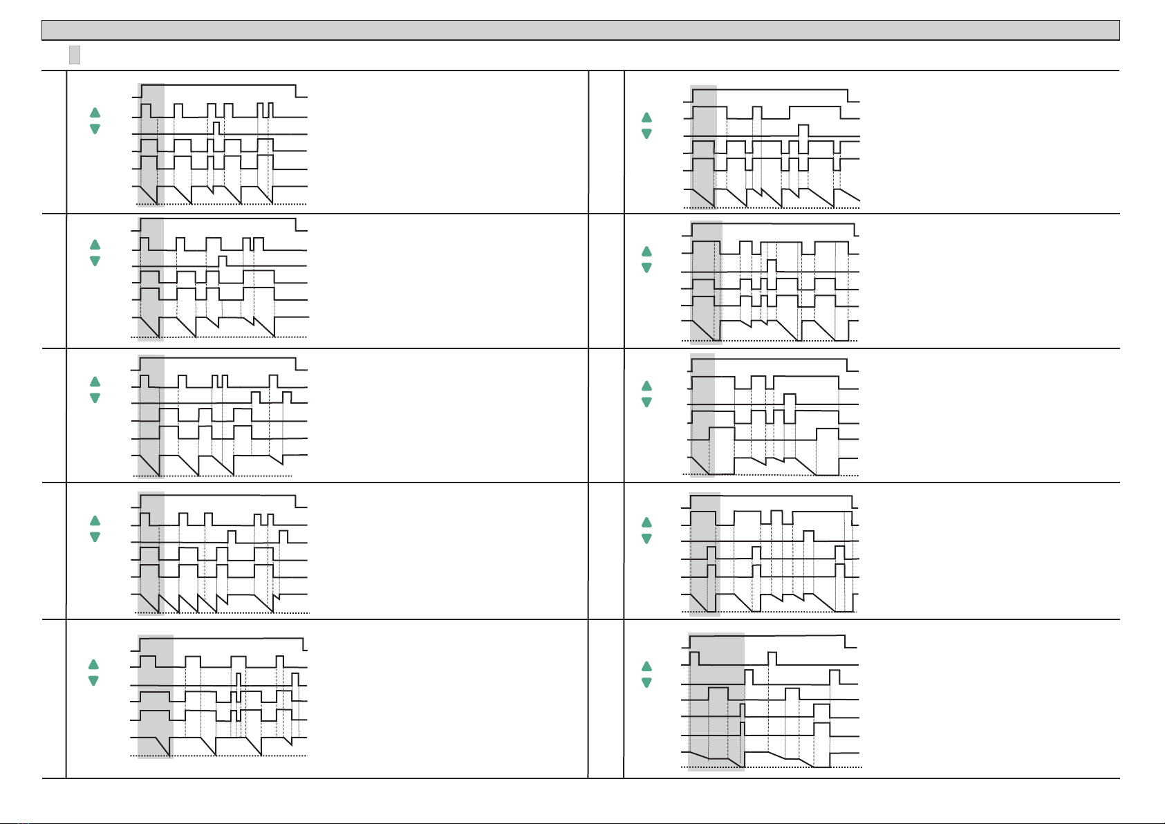
manuals.online logo
Brands
  1. Home
  2. •
  3. Brands
  4. •
  5. sisel
  6. •
  7. Timer
  8. •
  9. sisel ENDA ETM2432 User manual

sisel ENDA ETM2432 User manual

230V AC ±%10, 50/60Hz or 12/24V AC/DC %10, 50/60Hz or 9-30V DC/7-24V AC, 50/60Hz±
Max. 7VA
2.5mm²'lik screw-terminal
±%1
Scale
Sensitivity
Time Accuracy
Indıcator
EMC
START INPUT
Input Type Mechanical contact (Minimum = 50ms)
OUTPUT
Out 2 Relays: 250V AC, 8A (for resistive load), NO and NC control output.
30.000.000 Switching for no-load operation; 300.000 switching for 8A resistive load at 250VAC.
Selectable 99:59 min. or hour.
1 second.
HOUSING
ENDA ETM2432 DIGITAL TIMER
2
60mm 5mm
77mm
35mm
GATE INPUT
Input Type
RESET INPUT
Input Type
GATE
START
RESET
+12V
8 6 8 0 4 0 7 7 1 1 7 0 3
8 6 8 0 4 0 7 7 1 1 7 1 0
1 2 3 4 5 6 7 8 9 10
ENDA INDUSTRIAL ELECTRONICS
SN: XXXXXXXXX
ETM2432-230VAC
DIGITAL TIMER
230V AC +10% -20%
50/60Hz
11 12
Made In Turkey
OUT1
250V AC 8A RESISTIVE LOAD
1 2 3 4 5 6 7 8 9 10
ENDA INDUSTRIAL ELECTRONICS
SN: XXXXXXXXX
ETM2432-24
DIGITAL TIMER
24V AC/DC +10% -20%
50/60Hz
11 12
Made In Turkey
OUT2
GATE
RESET
START
+12V
250V AC 8A RESISTIVE LOAD
OUT1
OUT2
71,5mm
29,5mm
2
1
GATE
START
RESET
+12V
1 2 3 4 5 6 7 8 9 10
ENDA INDUSTRIAL ELECTRONICS
SN: XXXXXXXXX
ETM2432-230VAC
DIGITAL TIMER
230V AC +10% -20%
50/60Hz
11 12
Made In Turkey
OUT1
250V AC 8A RESISTIVE LOAD
OUT2
8680407711710
Read this document carefully before using this device. The guarantee will be expired by device
demages if you don't attend to the directions in the user manual. Also we don't accept any
compensations for personal injury, material damage or capital disadvantages.
Thank you for choosing ENDA ETM2432 digital timer.
* 77 x 35mm sized.
* Dual contact output for timing control.
* External start, reset, and gate inputs.
* Hours - minutes and minutes - seconds indications can be selected.
* Scale 0:01 .... 99:59 minutes
0:01 .... 99:59 hours
* Time increasing and decrement steps can be adjusted.
* Counting in downward direction.
* Start and stop process can be controlled by the front panel.
* 8 different warning tones.
* Upper and lower limits can be adjusted to setpoint value.
* CE marked according to European Norms.
CONNECTION DIAGRAM
ENDA ETM2432 is intended for installation within control panels. Make sure that the device is
used only for intended purpose. The shielding must be grounded on the instrument side. During an
installation, all of the cables that are connected to the device must be free of electrical power. The
device must be protected against inadmissible humidity, vibrations, severe soiling. Make sure
that the operation temperature is not exceeded. All input and output lines that are not connected to
the supply network must be laid out as shielded and twisted cables. These cables should not be close to the
power cables or components. The installation and electrical connections must be carried out by a qualified staff
and must be according to the relevant locally applicable regulations.
7
8
SUPPLY:
NOTE :
184-253V AC
50/60Hz 5VA
Phase
Neutral 230V AC
Supply
Switch
Cable size: 1,5mm²
Fuse
F 100 mA
250V AC
Fuse should
be connected.
1) Mains supply cords shall meet the requirements
of IEC 60227 or IEC 60245.
2) In accordance with the safety regulations, the
power supply switch shall bring the identification of
the relevant instrument and it should be easily
accessible by the operator.
Note
TECHNICAL SPECIFICATIONS
ENVIRONMENTAL CONDITIONS
Ambient/Storage temperature
Relative Humidity
Protection Class
Height
0 ... +50 / -25... +70
°C °C
Max. humidity 80% for temperatures up to 31°C decreasing linearly to 50% relative humidity at 40°C.
According to EN60529; Front panel: IP65 Rear panel : IP20
Max. 2000m
ELECTRICAL CHARACTERISTICS
Supply
Power Consumption
Wiring
Safety Requirements
Holding screw
0.4-0.5Nm.
Equipment is protected throughout by
DOUBLE INSULATION
Do not use the device in locations subject to corrosive and flammable gasses.
4 digits, 12.5mm, 7 segment red LED
EN 61326-1: 2013 (Performance criterion B is satisfied for EN 61000-4-3)
EN 61010-1: 2010 (Pollution degree 2, overvoltage category II)
Life Expectancy for Relay
For removing mounting clamps:
- Push the flush-mounting clamp
in direction 1 as shown in the
figure below.Then, pull out the
clamp in direction 2 .
Dimensions
Depth
Flush mounting
clamp Panel
Rubber
Packing
Flush mounting
clamp
Note:
1) Panel thickness should
be maximum 7mm.
2) If there is not 60mm free
space at the back side of
the device,it would be
difficult to remove it from
the panel.
Panel Cut-out
Mechanical contact (Minimum = 50ms)
according to DIN 43 700.Suitable for flush-panel mounting
5 1W77xH3 xD7 mm
Approx. 198g (A ) fter packing
Self extinguishing plastics
While cleaning the device, solvents (thinner, benzine, acid etc.) or corrosive materials must not be used.
Housing Type
Dimensions
Weight
Enclosure Materials
Order Code : ETM2432 -
1
1 - Supply Voltage
230VAC...230V AC
24............24V AC/DC
12............12V AC/DC
SM............9-30V DC / 7-24V AC
SET
SET
ETM232
ENDA
OUT1 HM
SET
SET
ETM2432
ENDA
OUT1 OUT2 HOUR MIN
START
STOP
DIGITAL TIMER
SET
SET
ETM232
ENDA
OUT1 HM
SET
SET
ETM2432
ENDA
OUT1 OUT2 HOUR MIN
START
STOP
DIGITAL TIMER
ETM2432-E-01-151012
SİSEL MÜHENDİSLİK ELEKTRONİK SAN. VE TİC. A.Ş.
Şerifali Mah. Y.Dudullu 34775
ÜMRANİYE/İSTANBUL-TURKEY
Tel : +90 216 499 46 64 Pbx. Fax : +90 216 365 74 01
url : www.enda.com.tr
Barbaros Cad. No:18 ENDA
TM
1/4
Programing Menu is opened and parameter is seen by pressing and buttons at same time. Switching between menu parameters is done by pressing button. W
ub-menu parameter is opened when pressing button.
In order to change sub-menu parameters value, press buttons while holding button down.When button is released , all changes will be saved to memory and related sub-menu parameter is returned.
Programming Menu is returned from sub-menu parameters by pressing buttons at same time. In the sub-menu ,
f no key is pressed for 10 seconds.
Conf hile one of menu parameter is seen,
s
all changes will be saved to memory and Running Mode is returned from sub-menu
i In programming menu , all changes can be saved to memory and Running Mode can be returned from programming menu either by pressing buttons at same time or
if no key is pressed for 10 seconds.
Programming Menu
TIME CONFIG MODE
Running Mode switches to Time Config Mode by pressing button. Display indicates configuration mode is opened . Desired timer set value can be set by pressing buttons. After desired timer value set,
by flashing
new timer set value is saved to memory and Running Mode is returned either by pressing button or by waiting 10 seconds.
28 00 27 59 28 00
SET
Time unit ;
hour (hour) or
min (minute)
Audible Warning Config ;
8 different sound type
can be selected.
If sd. is 1,
audible warning is enabled.
Time config lower limit ;
can be selected between
0:01 and t.uPL parameter
value.
Time config upper limit ;
can be selected between
t.loL parameter value
and 99:59.
Time config increase/decrease
step;
can be selected between
1 and 30.
Parameter security code ;
Parameter value must be
432.
( message is seen and
factory reset is started
if holding button down for 4
seconds while S.Cod )
dPAr
is 0.
t.5Et
t.lol
t.upl
In.dE
p.5EC
5.Cod
a. t.5.
a. t.c.
HOUR LED : Selected time unit is HOUR.
OUT1 LED : Specifies the output OUT1.
MIN LED : Selected time unit is
MINUTE.
OUT2 LED : Specifies the output OUT2.
SET
Timer value can be set in Running Mode , Parameter values can be set in Programming Mode and newly assigned parameter values can be saved .
After parameter values are changed , new values are saved to memory and Running Mode is returned either by pressing button or by waiting 10
seconds.
arameter or time set value changing) .
Menu parameters can be accessed in Programming Mode. Parameter set values can be increased. Timer set value can be increased in Time Config
Mode. Timer set value increases gradually accelerated by pressing continuously.
Timer is started by pressing button for 1 second , when Str.2 is selected (Except,either p
Timer and audible warning are stopped by pressing button for 1 second. when Str.2 is selected (Except,either parameter or time set value changing) .
Menu parameters can be accessed in Programming mode. Parameter set values can be decreased. Timer set value can be decreased in Time Config
Mode. Timer set value decreases gradually accelerated by pressing continuously.
If Str.t is Str.1, digital inputs
(start,reset,gate) are enabled.
If Str.2,
START/STOP buttons are enabled.
Str.t is
SET SET
Output type ;
9 different output type
can be selected.
(Out.1, Out.2, Out.3, ... , Out.9 )
Detailed in page 3/4.
t.SEt security parameter ;
nonE: Programming Menu
invisible.
P.YES: Menu
parameter can be changed.
P.no :
Programming
Programming Menu
parameter can only be seen.
ConF and tSEt security parameter ;
nonE: Programming Menu
invisible.
P.YES: Programming Menu
parameter can be changed.
P.no : Programming Menu
parameter can only be seen.
In order to set related parameter to desired value , hold button down,
when display is started to flash use buttons.
Value increases/decreases gradually accelerated by pressing
buttons continuously.
time
SET SET SET
hour min
Parameter Configuration Diagram
SET
Timer
set
value
28 00
Conf
tIME
5tr.t
0ut.t
5ond
hour
SET
SET
-
-
:
:
::
SET
SET
SET
SET
SET
SET SET
SET
SET
SET
SET
ETM232
ENDA
OUT1 HM
SET
SET
ETM2432
ENDA
OUT1 OUT2 HOUR MIN
START
STOP
DIGITAL TIMER
2/4 ETM2432-E-01-151012
SİSEL MÜHENDİSLİK ELEKTRONİK SAN. VE TİC. A.Ş.
Şerifali Mah. Y.Dudullu 34775
ÜMRANİYE/İSTANBUL-TURKEY
Tel : +90 216 499 46 64 Pbx. Fax : +90 216 365 74 01
url : www.enda.com.tr
Barbaros Cad. No:18 ENDA
TM
GATE USAGE
When device is powered, If START input is set
OUT1 and OUT2 relays are turned on.
When timer set value is expired ,
OUT1 and OUT2 relays are turned off.
If RESET input is set before
expires OUT1 and OUT2 relays are turned off
and timer set value is renewed.
timer set value
When device is powered, If START input is set
OUT1 and OUT2 relays are turned on.
When timer set value is expired,
OUT1 and OUT2 relays are turned off.
If RESET input is set before timer set value
is expired OUT1 and OUT2 relays are turned off
and timer set value is renewed.
If START input is set before timer set value
is expired , relays remain turned-on and timer set
value is renewed and timer starts counting down.
When device is powered , If START input is set
timer starts counting down.
OUT1 and OUT2 relays are turned on and
timer set value is renewed. If START input is
set again, OUT1 and OUT2 relays are turned off
and timer starts counting down.
İf RESET input is set OUT1 and OUT2 relays are
turned off and timer stops counting down.
When timer set value is expired,
When device is powered, If START input is set
OUT1 and OUT2 relays are turned on.
When timer set value is expired,
OUT1 and OUT2 relays are turned off , timer
set value is renewed and timer starts counting
down again.This process periodically continues.
If RESET input is set OUT1 and OUT2 relays are
turnef off and timer stops counting down.
When device is powered, If START input is set
OUT1 and OUT2 relays are turned on.When
When timer set value is expired,
is renewed.
If START input is set while timer counts down,
timer set value is renewed. When START input is
reset timer starts to counting down.
If RESET input is set
and timer stops counting down.
START
input is reset timer starts to counting down.
OUT1 and OUT2 relays are turned off and
timer set value
OUT1 and OUT2 relays are turned off
When device is powered, If START input is set
OUT1 and OUT2 relays are turned on and timer starts
counting down.
If START input is reset , timer value is renewed to
timer set value and timer starts to counting down.
If START input is set again , timer value is renewed
to timer set value.When timer set value is expired,
OUT1 and OUT2 relays are turned off and timer
value is renewed to timer set value.
If OUT1 and OUT2 relays are turned off
and timer value is renewed to timer set value.
RESET input is set,
When device is powered, If START input is set
OUT1 and OUT2 relays are turned on and timer starts
counting down from timer set value .When timer set value is
expired,OUT1 and OUT2 relays are turned off.If START input
is reset after an timer set value is expired,timer value is
renewed to timer set value.If START input is reset while
timer counts down ,OUT1 and OUT2 relays are turned off.
If RESET input is set while START input is set ,
OUT1 and OUT2 relays are turned off and
timer value is renewed to timer set value.If RESET input is
reset while START input is set , OUT1 and OUT2
relays are turned on and timer starts counting down
When device is powered, If START input is set
OUT1 relay is turned on and timer starts counting
down from timer set value.When timer set value is expired,
OUT2 relay is turned on.If START input is reset when
timer set value is expried, timer value is renewed to
timer set value . If START input is reset
while timer counts down OUT1 and OUT2 relays are turned off.
If RESET input is set while START input is set ,
OUT1 and OUT2 relays are turned off and timer value
is renewed to timer set value. If RESET input is reset
while START input is set , OUT1 relay is turned on and
timer starts counting down.
When device is powered, If START input is set ,
timer starts counting down. When timer set value is expired,
OUT1 and OUT2 relays are turned on.
If START input reset when timer set value is expired,
OUT1 and OUT2 relays are turned off and timer value is
renewed to timer set value.If START input is reset
while timer counts down , timer value is renewed to
timer set value.
If RESET input is set while START input is set , timer value is
renewed to timer set value.
If RESET input is reset while START input is set , timer value is
renewed to timer set value.and starts counting down.
When device is powered, If GATE input is set ,timer
set value is seen on display and timer stops counting down.
If
timer value is
renewed to timer set value.
GATE input is reset , timer continue where it remains.
If RESET input is set while GATE input is reset, OUT1
and OUT2 relays are turned off and
%100
%0
START
RESET
OUT1
OUT2
DISPLAY
POWER
GATE
%100
%0
Out.6
Out.7
Out.8
Out.9
START
RESET
OUT1
OUT2
DISPLAY
POWER
START
STOP
START
STOP
%100
%0
START
RESET
OUT1
OUT2
DISPLAY
POWER
%100
%0
START
STOP
START
RESET
OUT1
OUT2
DISPLAY
POWER
START
STOP
START
RESET
OUT1
OUT2
DISPLAY
POWER
%100
%0
START
STOP
NOTE : Selected area indicates the moment of power-up, if the external "START" input is active.
%100
%0
Out.1
Out.2
Out.3
Out.4
Out.5
%100
%0
%100
%0
START
RESET
OUT1
OUT2
DISPLAY
POWER
START
STOP
%0
START
RESET
OUT1
OUT2
DISPLAY
POWER
START
STOP
%100
START
RESET
OUT1
OUT2
DISPLAY
POWER
START
STOP
START
RESET
OUT1
OUT2
DISPLAY
POWER
START
STOP
START
RESET
OUT1
OUT2
DISPLAY
POWER
%100
%0
START
STOP
3/4 ETM2432-E-01-151012
ENDA ETM 2432 DIGITAL TIMER OUTPUT TYPES
Min. Unit
timE
5tr.t
0ut.t
5ond
Device time config
Device input control parameter
Device output control parameter
Device audible warning control parameter
5tr.1
0ut.1
5d.1
CONFIGURATION PARAMETERS
ENDA ETM2432 DIGITAL TIMER PARAMETERS
Max.
5tr.2
Out.9
5d.8
Factory
Settings
min
0ut.1
TIMER CONFIGURATION PARAMETERS
SECURITY PARAMETERS
hr:min
5tr.1
5d.1
t.LoL
Time config lower limit define parameter
t.uPL Time config upper limit define parameter
in.dE Time config increase/decrease coefficient parameter
00 01 99 59
99 59 99 59
00 02
00 01
: :
:
:
::
5.Cod Security code parameter 9999 0
0
A. t.5.
-
A. t.c.
-
Time config security parameter
Menu security parameter
P.YE5
P.YE5
Parameter
Name Functional Specification
min:sec.
Note 2: 5tr.t selected 5tr.2 ,Control is provided with device front panel START ( ) - STOP ( ) buttons. If
Note 1: 5tr.tselected 5tr.1, Control is provided with START - RESET - GATE inputs.If
Note 3: GATE input can be used for all 5tr.t and 0ut.t types.
Note 4: When 5tr.t parameter switched from 5tr.1 to 5tr.2 , device continue to work with present 0ut.t output setting.
Timer can be stopped with device front panel STOP( ) button in case of need.
Note 5: 5tr.2 to 5tr.1,
digital RESET input can be used instead of STOP button.
Cases in Note 4 also valid for 5tr.tparameter switched from
00 01
:99 59
:
Note 6: In Running Mode, if the , and keys are pressed together, revision number appears on display.
(In order to show the revision number, 5tr.t parameter must be set to 5tr.1 in Conf menu).
SET
SİSEL MÜHENDİSLİK ELEKTRONİK SAN. VE TİC. A.Ş.
Şerifali Mah. Y.Dudullu 34775
ÜMRANİYE/İSTANBUL-TURKEY
Tel : +90 216 499 46 64 Pbx. Fax : +90 216 365 74 01
url : www.enda.com.tr
Barbaros Cad. No:18
4/4 ETM2432-E-01-151012
ENDA
TM

Other sisel Timer manuals

sisel ENDA ATF02 User manual

sisel

sisel ENDA ATF02 User manual

sisel ENDA ATSD02 User manual

sisel

sisel ENDA ATSD02 User manual

sisel ENDA ETM742 User manual

sisel

sisel ENDA ETM742 User manual

sisel Enda ATSD02 User manual

sisel

sisel Enda ATSD02 User manual

Popular Timer manuals by other brands

Omron H8CA-S Series manual

Omron

Omron H8CA-S Series manual

R.U. Ready Speed-Timer 3000 operating instructions

R.U. Ready

R.U. Ready Speed-Timer 3000 operating instructions

Bosch WT PSI 6 Series operating instructions

Bosch

Bosch WT PSI 6 Series operating instructions

Alfano 6 manual

Alfano

Alfano 6 manual

TFA CONTRA instruction manual

TFA

TFA CONTRA instruction manual

GIZMO ENGINEERING T4 instructions

GIZMO ENGINEERING

GIZMO ENGINEERING T4 instructions

WESTEK TE1606 instruction manual

WESTEK

WESTEK TE1606 instruction manual

Autonics FSE Series product manual

Autonics

Autonics FSE Series product manual

Velleman K2579 Assembly manual

Velleman

Velleman K2579 Assembly manual

Favero COIN TIMER Series manual

Favero

Favero COIN TIMER Series manual

Zurn Wilkins EST Installation, Testing, Maintenance Instructions

Zurn Wilkins

Zurn Wilkins EST Installation, Testing, Maintenance Instructions

schmersal SRB-E-402FWS-TS operating instructions

schmersal

schmersal SRB-E-402FWS-TS operating instructions

Defiant 29068 Use and care guide

Defiant

Defiant 29068 Use and care guide

FATT Advance Plus instruction manual

FATT

FATT Advance Plus instruction manual

Prince Castle 840-T4 Specifications

Prince Castle

Prince Castle 840-T4 Specifications

AVT 1820 quick start guide

AVT

AVT 1820 quick start guide

Intermatic T8845PV Programming instructions

Intermatic

Intermatic T8845PV Programming instructions

HydroSure YL21025 Instruction

HydroSure

HydroSure YL21025 Instruction

manuals.online logo
manuals.online logoBrands
  • About & Mission
  • Contact us
  • Privacy Policy
  • Terms and Conditions

Copyright 2025 Manuals.Online. All Rights Reserved.