Beko BARBAROS User manual

BARBAROS
BUILT IN BI OVEN
SERVICE MANUAL

1.CONTENTS……………………………………………………………………………………………………………………………….2
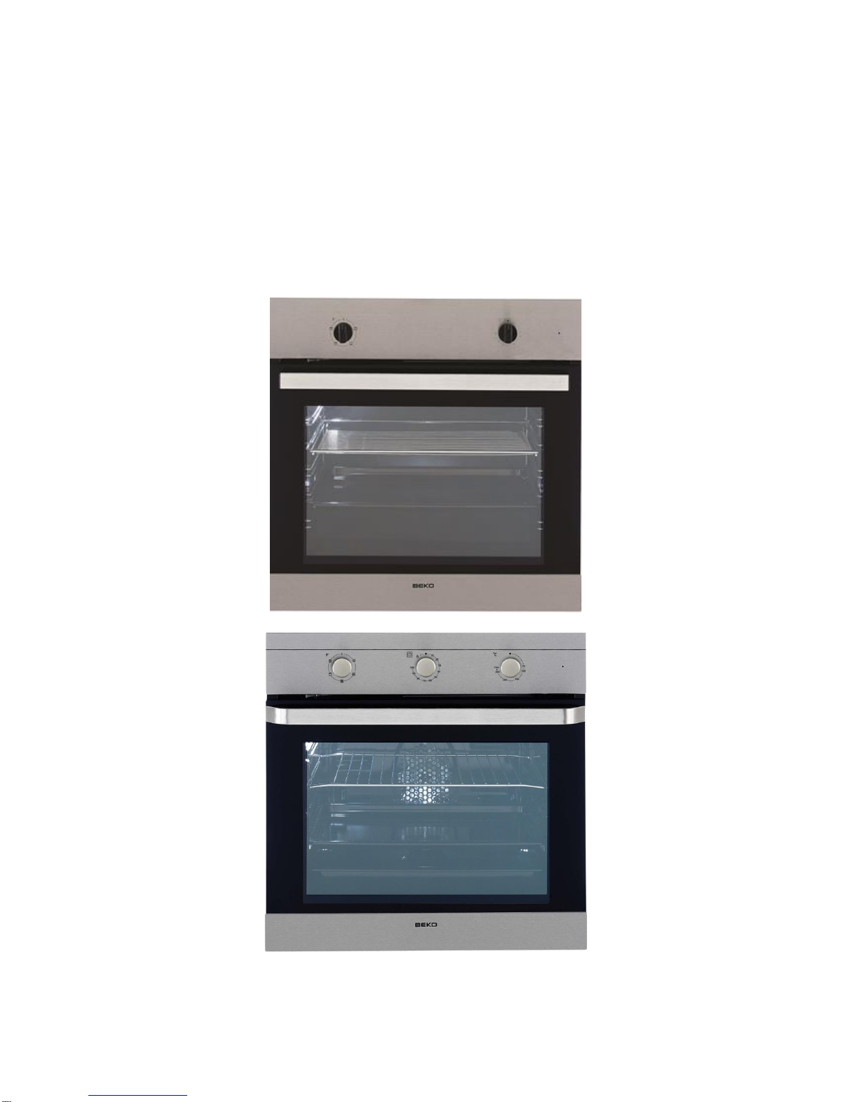
2.COVER……………………………………………………………………………………………………………………………………..3
3. SAFETY WARNING ....................................................................................................................4
3.1 GENERAL SAFETY ...............................................................................................................................4
3.2. SAFETY FOR CONFİGURATİONS .............................................................................................................4
3.3 INFORMATİONS FOR CONSUMER ...........................................................................................................5
4. TECHNICAL SPECIFICATIONS .....................................................................................................6
5. PRODUCT ASSEMBLY/ ASSEMBLY RULES/ SETTINGS .................................................................7
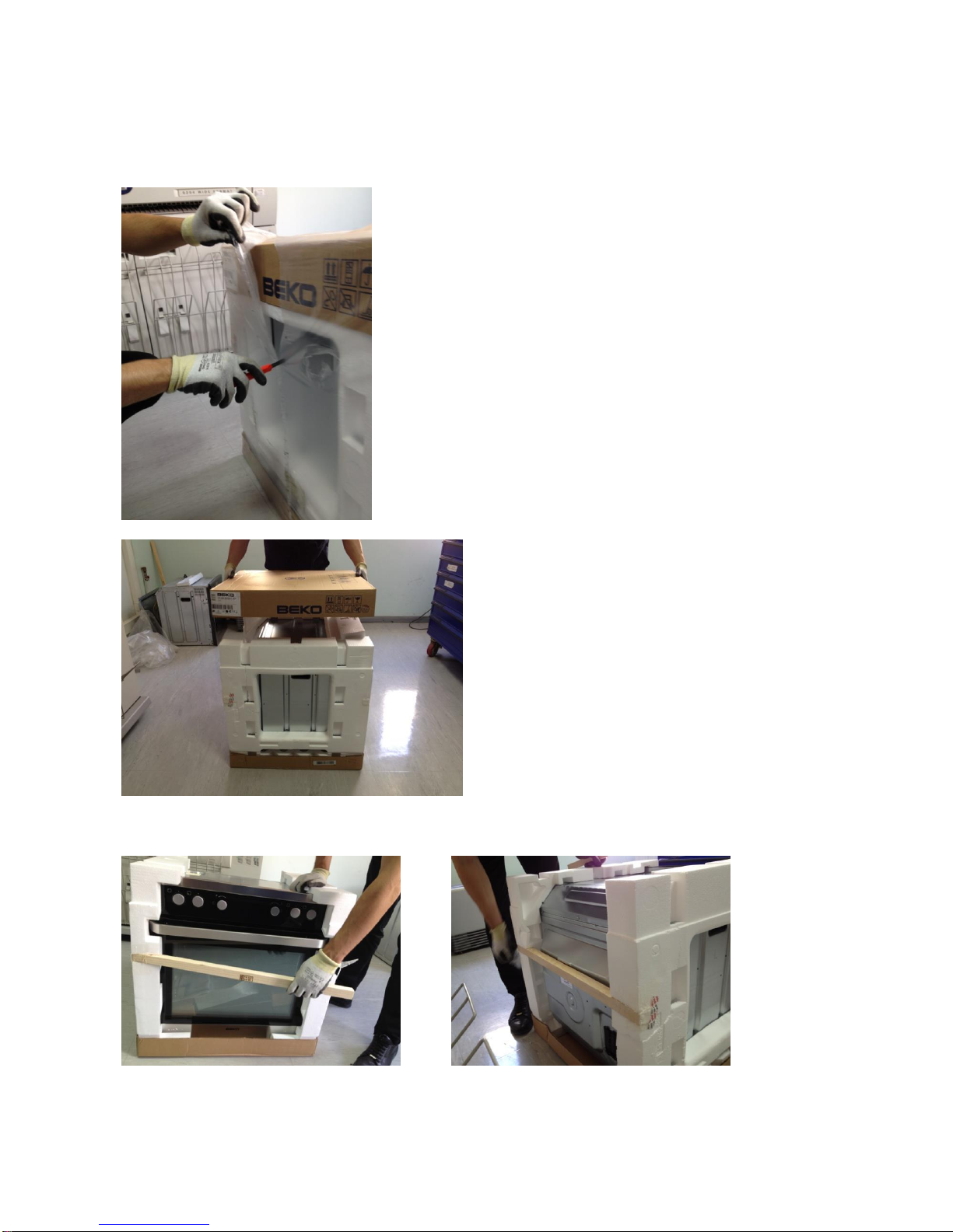
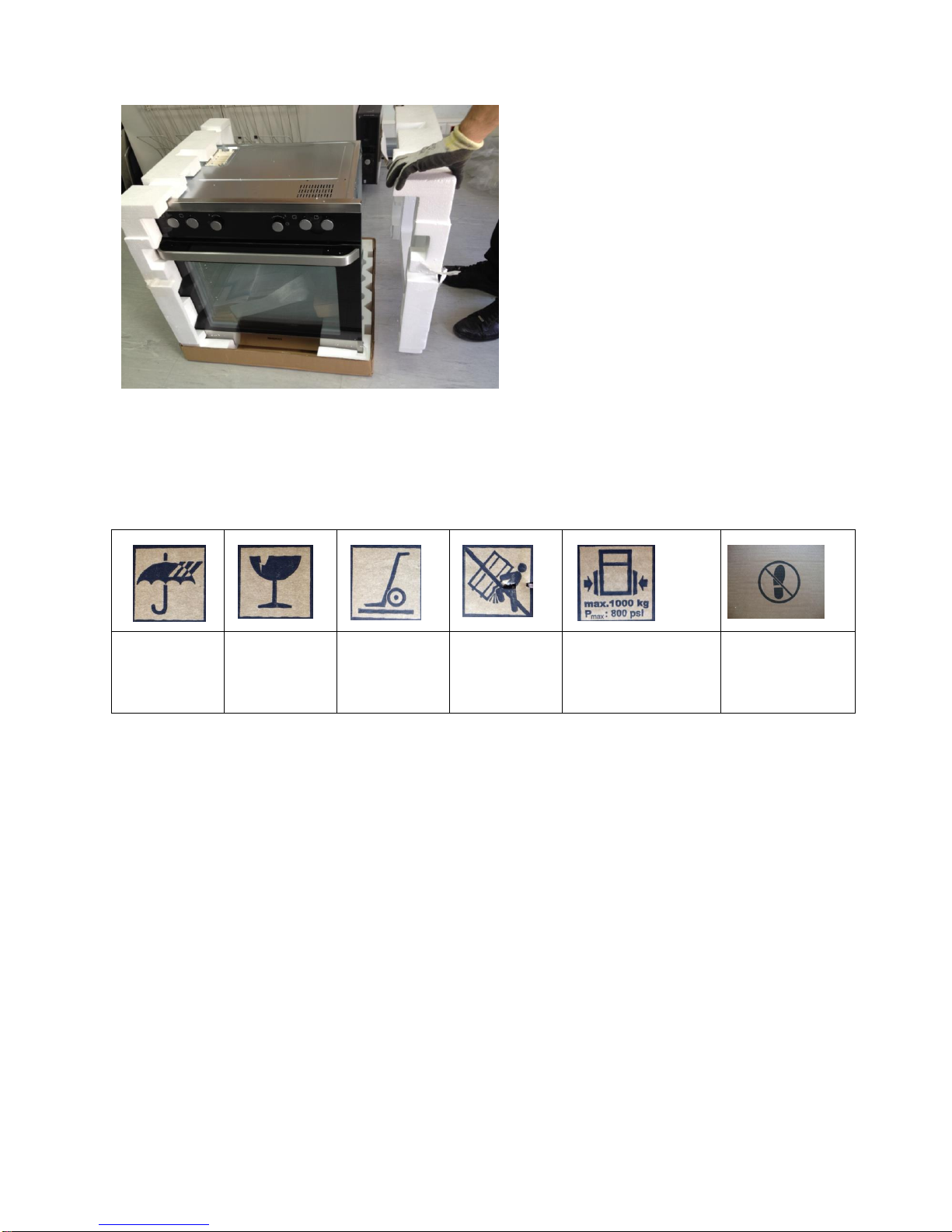
5.1 PRODUCT TRANSPORTATION ................................................................................................................7
5.2UNPACKING PRODUCT ........................................................................................................................8
5.3 CONTROLLING THE SETUP PLACE AND ENERGY SOURCES ...........................................................................10
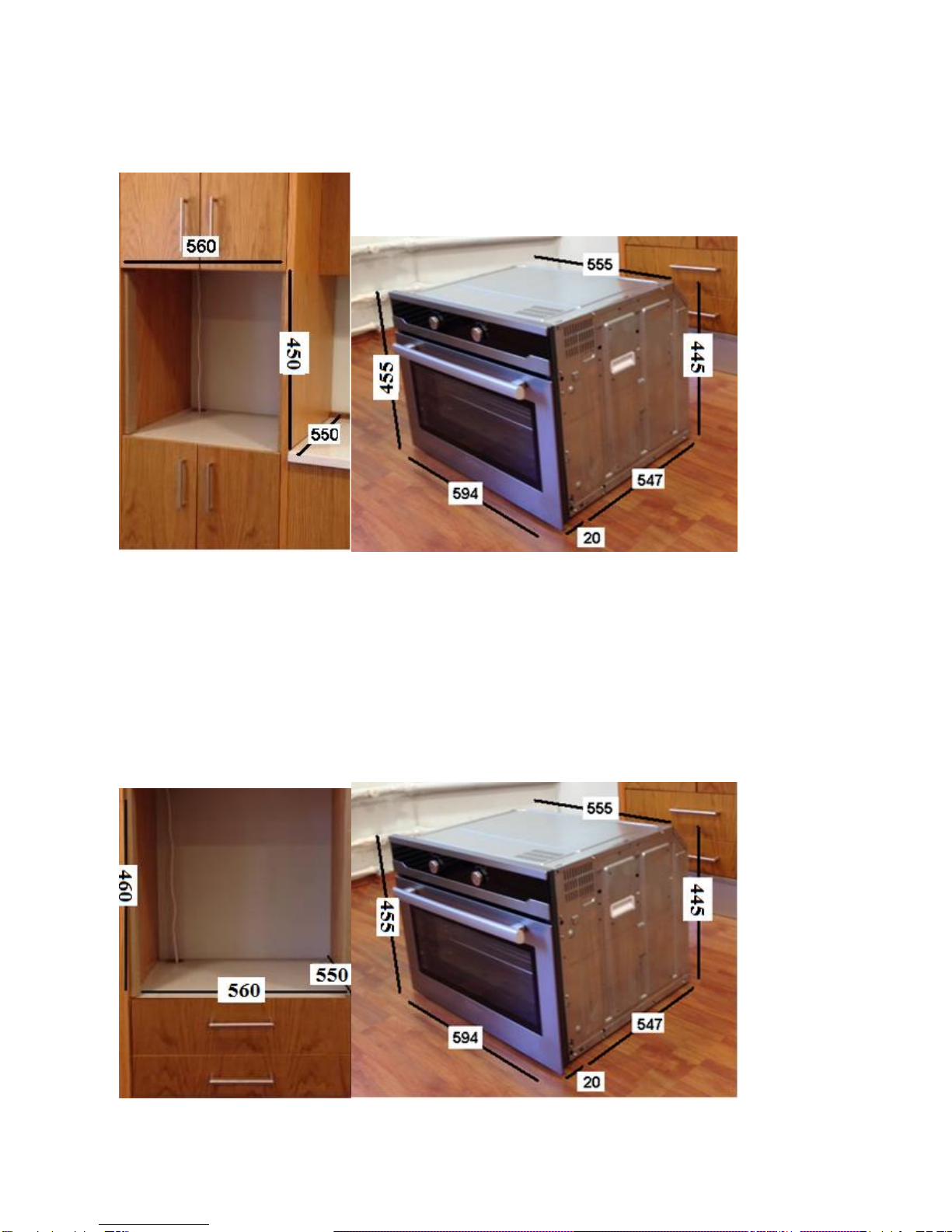
5.3.1 Measurement control of the mounting place ......................................................................10
5.3.2 Control of the electrical installation.....................................................................................11
5.4 ELECTRİCAL CONNECTİON...................................................................................................................11
5.5 MOUNTING THE PRODUCT.................................................................................................................12
6. USE OF THE PRODUCT ............................................................................................................14
6.1 FİRST USE.......................................................................................................................................14
6.2 WORK FUNCTIONS ...........................................................................................................................16
6.2.1 Work Functions.....................................................................................................................16
USING THE CLOCK ..................................................................................................................................19
7.BY PRODUCTS/PRODUCTS LABELS USED..................................................................................22
7.1 PERIPHERALACCESSORIES ..................................................................................................................22
7.2TAGS AND DESCRIPTIONS USED IN THE PRODUCT ....................................................................................23
7.2.1 Type the label .......................................................................................................................23
7.2.2 Barcode Label .......................................................................................................................23
7.3.3 Energy Label; ........................................................................................................................24
8. GENERAL PRINCIPLE OF OPERATION.......................................................................................26
8.1 THE NORMAL OPERATING MODE........................................................................................................27
9. LIST OF COMPONENTS / COMPONENT WORKING PRINCIPLE...................................................28
9.1 TECHNICAL SPECIFICATIONS OF THE COMPONENTS ..................................................................................28
9.2 COMPONENT CODE OF CONDUCT........................................................................................................28
10. FAULT FLOW / FAULT FINDING DIAGRAMS ...........................................................................31
10.1.RESİSTANCE FAULTS .......................................................................................................................31
Resistance does not work;the food is not cooked .........................................................................31
10.2 LAMP FAULT .................................................................................................................................32
Furnace is working but the oven does not illuminate ...................................................................32
Oven does not work,oven lamp does not light..............................................................................33
10.3 TERMOSTAT FAULT.........................................................................................................................34
Furnace runs continuosly,the thermostat is not tripped...............................................................34

10.4 THERMİNAL FAULT .........................................................................................................................35
There is no power from the terminal does not diffuse into the electric furnace...........................35
When the fuse blows the oven is plugged into the Wall socket....................................................36
11.MEASUREMENTS TO BE DONE TO FİND THE FAULT COMPONENTS.........................................37
12. COMPONENT ASSEMBLY / DISASSEMBLY BE USED IN EQUIPMENT........................................40
13.COMPONENT ASSEMBLY / DİSASSEMBLY...............................................................................41
13.1 REMOVING THE CONTROL PANEL .......................................................................................................41
13.2 CHANGING THE FRONT COVER...........................................................................................................43
13.3 REPLACING THE FRONT DOOR HINGE ..................................................................................................45
13.4 CHANGİNG THE REMOVABLE GLASS COVER 3........................................................................................46
13.5 CHANGING THE HANDLE .................................................................................................................49
13.6 CHANGING THE UPPER WALL ............................................................................................................51
13.7 REPLACEMENT OF THE COMUTATORS .................................................................................................52
13.8 REPLACEMENT OF THE OVEN THERMOSTAT ..........................................................................................53
13.9 REPLACEMENT OF THE THERMOSTAT BULB...........................................................................................54
13.10 REPLACEMENT OF THE Bİ-METAL THERMOSTAT ..................................................................................56
13.11 CHANGING THE ENGINE COOLING ....................................................................................................56
13.12 CHANGING THE VENTILATION PLATE .................................................................................................57
13.13 AIR-CONDITIONING THERMOSTAT REPLACEMENT................................................................................59
13.14 REMOVING THE REAR WALL ............................................................................................................60
13.15 REMOVING THE SIDE DECOR ...........................................................................................................63
13.16 REPLACEMENT THE BOTTOM PLATE .................................................................................................63
13.17 CHANGİNG THE SWİTCH.................................................................................................................65
13.18 CATALYTIC REMOVAL OF THE INNER SIDE WALL ...................................................................................67
13.19 CHANGING THE GRID RESISTANCE ....................................................................................................68
13.20 CHANGING THE OVEN HEATING .......................................................................................................70
13.21 REPLACING TURBO RESISTANCE.......................................................................................................72
13.22 REPLACEMENT OF THE OVEN SEAL....................................................................................................74
13.23 REPLACING TURBO ENGINE.............................................................................................................75
13.24 CHANGING TERMINAL ...................................................................................................................76
13.25 REPLACING THE WIRE RACK ............................................................................................................78
13.26 REPLACING THE OVEN LAMP ...........................................................................................................78
13.27 SQUARE OVEN LAMP REPLACEMENT .................................................................................................79
13.28 REPLACEMENT THE CATALYZER........................................................................................................80
13.29 REPLACEMENT THE PYRO DOOR LOCK ...............................................................................................81
13.30 REPLACEMENT THE METAL SHEET OF PYRO VENTILATION ......................................................................83
13.31 REPLACEMENT THE ENGINE OF PYRO COOLING ...................................................................................85
13.32 REPLACEMENT THE ENGINE THERMOSTAT OF COOLING.........................................................................85

3. SAFETY WARNING
This section contains safety instructions that will help protect from risk of personal
injury or property damage.
Throughout this user manual the following symbols are used.
Important information or useful hints about usage.
Warning of hazardous situations with regard to life and property.
Warning of electric shock..
Warning of risk of fire.
Warning of hot surfaces.
3.1 General Safety
•This appliance can be used by children aged from 8 years and above and
persons with reduced physical, sensory or mental capabilities or lack of
experience and knowledge if they have been given supervision or instruction
concerning use of the appliance in a safe way and understand the hazards
involved.
Children shall not play with the appliance. Cleaning and user maintenance shall
not be made by children without supervision.
•Installation and repair procedures must always be performed by Authorized
Service Agents. The manufacturer shall not be held responsible for damages
arising from procedures carried out by unauthorized persons which may also void
the warranty. Before installation, read the instructions carefully.
•Do not operate the product if it is defective or has any visible damage.
Control that the product function knobs are switched off after every use.
3.2. Safety for Configurations
Control the area of the configuration is appropriate.
It is important that sources of energy is near the product.
Do not lay the network wire on the hot surface.If not wire coalasces and this couses
short circuit.
Be cafeful during the configuration wire is not cut or deformed.If not change them with
new one.
There is not a component to release the gases resulting of the burning in the
product.Set up the product according to the configuration rules.Especially,be careful
with the airing tools and needs.

3.3 Informations for Consumer
Product may be hot during the usage.Do not touch with hot parts ,inside the
oven,heating components etc. .When the product is working it is hot so do not put
combustable materials near the product.
Do not wash the product with water! It is dangerous for electrick shock!Ürünü, üzerine s
Do not heat the closed preserve jar or can with the product.Presure may cause the
explosion.
Do not clean while the product is working.
Do not change in anything on the porduct or any repair instead of some problems in the
user guide.
If there is no door or window for airing ,blower must be built.
Use a glove that is heat resistant during put/remove the meal to the hot oven
Do not use the product if front glass is broken or removed or any deformation on the
tweel block.
When tweel block is open, be careful about children do not sit down on it.
Do not hang cloth or towel or something like them on handle.

4. TECHNICAL SPECIFICATIONS
Voltage / frequency
220-240 V ~ 50 Hz
Total power consumption
2.5 kW
Fuse
min. 16 A
Cable type / section
H05VV-FG 3 x 1,5 mm2
Cable length
max. 2 m
External dimensions (height / width / depth)
595 mm/594 mm/567 mm
Installation dimensions (height / width / depth)
**590 or 600 mm/560 mm/min. 550 mm
Main oven
Multifunction oven
Inner lamp
15/25 W
Grill power consumption
2.2 kW

5. PRODUCT ASSEMBLY/ ASSEMBLY RULES/ SETTINGS
5.1 Product Transportation
Control the view of the product for any damage which may occur in the carrying period.
To carry or move the product, do not use
door or handle of the product. Door,
handle or hinges can be harmed.
Product should be carried by two person for
safety of the product and ergonomics
When the product is being carried or the
product is being put to the ground, do not put it
keenly, do not drag it and do not skid it from
stairs.

5.2 Unpacking Product
To consider product changing in the mounting process, please do not harm package,
product and the product package when extracting.
Take lathes on the product’s front and behind sides, like shown in below.
Extract package with a knife without harming top
and bottom carton.
Take the top carton.

Symbols on the package of the products and meaning of them;
Preserve
from damp
Fragile
Carry with
barrow in
this way.
Do not carry
the product
like in the
picture
Carry the product
in this way by
squeezing with
clamp
Do not step on
the product.
Take stripers which are left and
right side of the products.

5.3 Controlling the setup place and energy sources
5.3.1 Measurement control of the mounting place
In the setup of the product, local standards about electric and gas should be applied.
Product is designed according to kitchens’ bench so it is placeable. Appropriate
safety interval should be between kitchen wall and the furniture. For appropriate
interval, please look at the picture.(values are mm type).
Used sides, synthetic laminates and glues should be durable to the head (min.100°C).
Product should be stayed with the same height with kitchen furnitures.
If there is a drawer bottom of the oven, a shelf should be used between oven and the
drawer.

5.3.2 Control of the electrical installation
The following values for the control of electrical installation products with the product should
be considered.
Voltage / frequency
220-240 V ~ 50 Hz
Total power consumption
3,1kW
Fuse
min. 16 A
Cable type / section
H05VV-FG
3 x 1,5 mm2
Cable length
max. 2 m
5.4 Electrical connection
Connect the product to a grounded outlet/line protected by a fuse of suitable capacity as
stated in the "Technical specifications" table. Have the grounding installation made by a
qualified electrician while using the product with or without a transformer. Our company
shall not be liable for any damages that will arise due to using the product without a
grounding installation in accordance with the local regulations.
Connection must comply with national regulations.
The mains supply data must correspond to the data specified on the type label of the
product.
Open the front door to see the type label.

5.5 Mounting the product
Taking care not to jam the power cord of the oven, slide the cabinet slots, align and fix it.
Right and left in the oven (as shown in the figure) There are screw holes on the right and
left of the oven (as shown in the figure) for mounting the furnace furnishings.


6. Use Of The Product
Plug in the power cord and turn on the insurance of the device.
6.1 First Use
1 Function button
2 Temperature button
3 Signal lamp
Select the function and temperature;
1 Function button
2 Temperature button
1 Function button
2 Mechanical clock
3 Temperature button
4 Temperature lamp
Temperature and the selected operating mode;

1 Function button
2 Temperature button
Turn the thermostat knob to the
desired temperature.
Set the function switch to the
desired operating mode.

The oven heats up to the set temperature and maintains this temperature. During heating,
temperature lamp illuminates.
Turning off the electric oven
6.2 Work Functions
The sequence of operating modes shown here may differ from the arrangement on your
appliance.
6.2.1 Work Functions
Top and bottom heating
Bottom Heat
Function button and the
temperature knob off (upper)
position.
Top and bottom heating is on. Foods
are heated simultaneously from
above and below. For Example;
cakes are suitable for cakes and pies
in casserole or baking mold. Make
cooking with a single tray.
Only the lower heating is on. Pizza
and the bottom is suitable for desired
browning of food.

Fan assisted top / bottom heating
NOTE: When the temperature outside the oven door is opened to escape the fan motor
does not work.
Large Grid
Fan assisted grill great
With upper and lower heating (rear
wall) open fan. Hot air, anywhere in
the furnace evenly distributed fan
and quickly. Make cooking with a
single tray. You can do a lot of
cooking tray.
Top heating, bottom heating and
warm air heating works. Each side of
the product to be cooked is cooked
uniformly and quickly. You can
yapın.çok baking tray with baking
tray only.
Grilled effect is not as strong as in
the normal grid.

Fan Assisted Cooking
Keep warm
High heat cleaning
Fan heater heated by hot air,
anywhere in the oven by the fan
is distributed evenly and quickly.
Very baking tray and can in most
cases there is no need for
preheating.
Food is used to keep the ready-
to-long-term service temperature.
Do not use for cooking food.
High temperature furnace used
for self-cleaning. Read the
descriptions for these functions in
the maintenance and cleaning

Using the clock
Starting the cooking process,
Place the meal in oven,
Set the cooking time by turning
the knob clockwise to time.
Select the operating mode and
temperature.

If necessary, up to pre-heat for about 5 minutes.
When the cooking time finishes,
the rotary knob clockwise
automatically reverse time.
Put the grid icon on the function
symbol that you want
Then, set the grill temperature
you want.
Table of contents
Other Beko Oven manuals

Beko
Beko GE-15320-DX User manual

Beko
Beko BBVM13400XDS User manual

Beko
Beko OIM 22100 User manual

Beko
Beko OIE 24300 B User manual

Beko
Beko MCSE 68102 GW User manual

Beko
Beko CSE64010D User manual

Beko
Beko BBIS17300BSEA User manual

Beko
Beko OIF 22309 User manual

Beko
Beko CSM 62321 G User manual

Beko
Beko OIM 22101 X User manual

Beko
Beko OIC 22000 User manual

Beko
Beko WOS30200SS User manual

Beko
Beko CSM 69300 G User manual

Beko
Beko MSH30B User manual

Beko
Beko BDVC 664 User manual

Beko
Beko BBIM11300XFP User manual

Beko
Beko QOM246B User manual

Beko
Beko OIE 21000 User manual

Beko
Beko BBIM174N0BE User manual

Beko
Beko OIC 21003 User manual