Belden Grass Valley MCP 450 User manual

3922 496 32291 February 2018 v1.1
Software v1.3.0.0
MCP 450
User’s Guide
Master Control PC

Copyright
Copyright Grass Valley Canada 2010-2017. Copying of this document and giving it to
others, and the use or communication of the contents thereof, are forbidden without
express authority. All rights are reserved in the event of the grant of a patent or the
registration of a utility model or design. Liable to technical alterations in the course of
further development.
Trademarks
Grass Valley, MCP Series, LDX Series and derivatives are trademarks of Belden Inc. or
Grass Valley Canada. All other tradenames referenced are service marks, trademarks,
or registered trademarks of their respective companies.
Website
Visit the Grass Valley public website to download the latest user’s guide updates and
additional information about your broadcast product:
www.grassvalley.com

MCP 450 Master Control PC User’s Guide (v1.1) 3
Table of contents
Chapter 1 – Introduction
1.1 Application . . . . . . . . . . . . . . . . . . . . . . . . . . . . . . . . . . . . . . . . . . . . . . . . . . . . . . . . . . . 7
1.2 Embedded Box Computer. . . . . . . . . . . . . . . . . . . . . . . . . . . . . . . . . . . . . . . . . . . . . . . 7
1.3 Features . . . . . . . . . . . . . . . . . . . . . . . . . . . . . . . . . . . . . . . . . . . . . . . . . . . . . . . . . . . . .8
1.4 Configuration . . . . . . . . . . . . . . . . . . . . . . . . . . . . . . . . . . . . . . . . . . . . . . . . . . . . . . . . .9
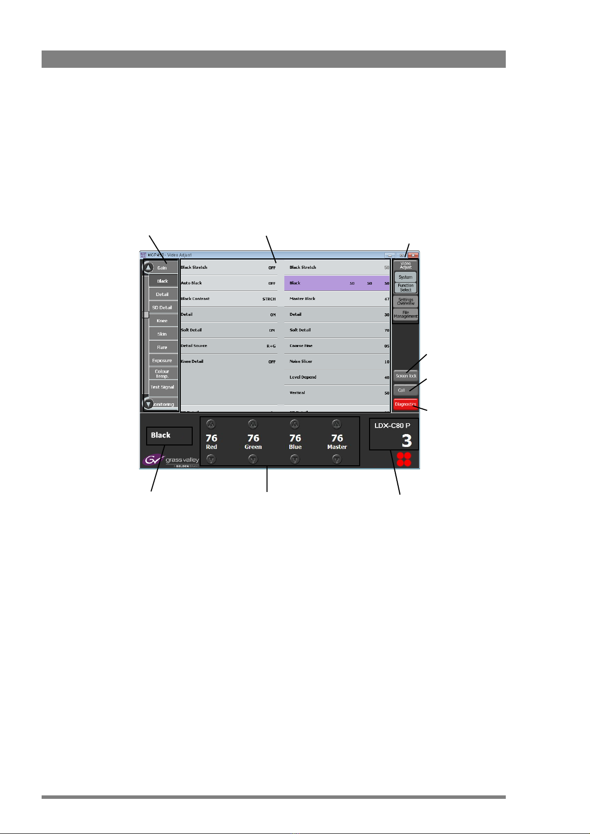
1.5 Screen layout . . . . . . . . . . . . . . . . . . . . . . . . . . . . . . . . . . . . . . . . . . . . . . . . . . . . . . . .10
1.5.1 Single camera mode . . . . . . . . . . . . . . . . . . . . . . . . . . . . . . . . . . . . . . . . . . . . . 10
1.5.2 Multiple camera mode. . . . . . . . . . . . . . . . . . . . . . . . . . . . . . . . . . . . . . . . . . . . 11
Chapter 2 – Installation
2.1 Connecting the embedded box computer. . . . . . . . . . . . . . . . . . . . . . . . . . . . . . . . .13
2.2 Setting up the embedded box computer. . . . . . . . . . . . . . . . . . . . . . . . . . . . . . . . . . 14
2.2.1 Power up configuration . . . . . . . . . . . . . . . . . . . . . . . . . . . . . . . . . . . . . . . . . . . 14
2.2.2 Screen resolution. . . . . . . . . . . . . . . . . . . . . . . . . . . . . . . . . . . . . . . . . . . . . . . . 14
2.2.3 Changing network settings . . . . . . . . . . . . . . . . . . . . . . . . . . . . . . . . . . . . . . . . 14
2.3 Setting up the MCP application . . . . . . . . . . . . . . . . . . . . . . . . . . . . . . . . . . . . . . . . . 17
2.3.1 Software Version . . . . . . . . . . . . . . . . . . . . . . . . . . . . . . . . . . . . . . . . . . . . . . . .17
2.3.2 HW Model Name. . . . . . . . . . . . . . . . . . . . . . . . . . . . . . . . . . . . . . . . . . . . . . . . 17
2.3.3 Serial nr . . . . . . . . . . . . . . . . . . . . . . . . . . . . . . . . . . . . . . . . . . . . . . . . . . . . . . .17
2.3.4 PID . . . . . . . . . . . . . . . . . . . . . . . . . . . . . . . . . . . . . . . . . . . . . . . . . . . . . . . . . . . 17
2.3.5 IP Address . . . . . . . . . . . . . . . . . . . . . . . . . . . . . . . . . . . . . . . . . . . . . . . . . . . . . 17
Chapter 3 – Operation
3.1 Operating a single camera . . . . . . . . . . . . . . . . . . . . . . . . . . . . . . . . . . . . . . . . . . . . . 19
3.1.1 Switching to single camera mode . . . . . . . . . . . . . . . . . . . . . . . . . . . . . . . . . . . 19
3.1.2 Function sets . . . . . . . . . . . . . . . . . . . . . . . . . . . . . . . . . . . . . . . . . . . . . . . . . . .19
3.1.3 Function field . . . . . . . . . . . . . . . . . . . . . . . . . . . . . . . . . . . . . . . . . . . . . . . . . . .20
3.1.4 Changing values. . . . . . . . . . . . . . . . . . . . . . . . . . . . . . . . . . . . . . . . . . . . . . . . . 21
3.1.5 Secondary color corrector . . . . . . . . . . . . . . . . . . . . . . . . . . . . . . . . . . . . . . . . . 22
3.2 Operating multiple cameras . . . . . . . . . . . . . . . . . . . . . . . . . . . . . . . . . . . . . . . . . . . . 23
3.2.1 Multiple camera mode. . . . . . . . . . . . . . . . . . . . . . . . . . . . . . . . . . . . . . . . . . . . 23
3.2.2 Function sets . . . . . . . . . . . . . . . . . . . . . . . . . . . . . . . . . . . . . . . . . . . . . . . . . . .23
3.2.3 Function matrix . . . . . . . . . . . . . . . . . . . . . . . . . . . . . . . . . . . . . . . . . . . . . . . . .24
3.2.4 Changing values. . . . . . . . . . . . . . . . . . . . . . . . . . . . . . . . . . . . . . . . . . . . . . . . . 24
3.2.5 Operating combined functions . . . . . . . . . . . . . . . . . . . . . . . . . . . . . . . . . . . . . 25
3.2.6 Monitoring cameras. . . . . . . . . . . . . . . . . . . . . . . . . . . . . . . . . . . . . . . . . . . . . . 25
3.3 Selecting functions . . . . . . . . . . . . . . . . . . . . . . . . . . . . . . . . . . . . . . . . . . . . . . . . . . . 26
3.3.1 Opening the Function Select window . . . . . . . . . . . . . . . . . . . . . . . . . . . . . . . .26
3.3.2 Selecting function groups . . . . . . . . . . . . . . . . . . . . . . . . . . . . . . . . . . . . . . . . .26
3.3.3 Selecting single functions . . . . . . . . . . . . . . . . . . . . . . . . . . . . . . . . . . . . . . . . . 27
3.3.4 Selecting all functions . . . . . . . . . . . . . . . . . . . . . . . . . . . . . . . . . . . . . . . . . . . . 27

4MCP 450 Master Control PC User’s Guide (v1.1)
3.4 Selecting cameras . . . . . . . . . . . . . . . . . . . . . . . . . . . . . . . . . . . . . . . . . . . . . . . . . . . .28
3.4.1 Information display. . . . . . . . . . . . . . . . . . . . . . . . . . . . . . . . . . . . . . . . . . . . . . .28
3.4.2 Selecting a camera (in single camera mode) . . . . . . . . . . . . . . . . . . . . . . . . . . .28
3.4.3 Selecting cameras (in multi camera mode) . . . . . . . . . . . . . . . . . . . . . . . . . . . .29
3.5 Managing groups. . . . . . . . . . . . . . . . . . . . . . . . . . . . . . . . . . . . . . . . . . . . . . . . . . . . .29
3.5.1 Creating a new group. . . . . . . . . . . . . . . . . . . . . . . . . . . . . . . . . . . . . . . . . . . . . 30
3.5.2 Editing a group . . . . . . . . . . . . . . . . . . . . . . . . . . . . . . . . . . . . . . . . . . . . . . . . . .30
3.5.3 Renaming a group . . . . . . . . . . . . . . . . . . . . . . . . . . . . . . . . . . . . . . . . . . . . . . .31
3.5.4 Deleting a group. . . . . . . . . . . . . . . . . . . . . . . . . . . . . . . . . . . . . . . . . . . . . . . . . 31
3.6 Managing files . . . . . . . . . . . . . . . . . . . . . . . . . . . . . . . . . . . . . . . . . . . . . . . . . . . . . . .32
3.6.1 File management . . . . . . . . . . . . . . . . . . . . . . . . . . . . . . . . . . . . . . . . . . . . . . . .32
3.6.2 Scene files menu . . . . . . . . . . . . . . . . . . . . . . . . . . . . . . . . . . . . . . . . . . . . . . . .32
3.6.3 Scene file actions. . . . . . . . . . . . . . . . . . . . . . . . . . . . . . . . . . . . . . . . . . . . . . . .33
3.6.4 Controlling multiple files . . . . . . . . . . . . . . . . . . . . . . . . . . . . . . . . . . . . . . . . . .35
3.6.5 Editing files . . . . . . . . . . . . . . . . . . . . . . . . . . . . . . . . . . . . . . . . . . . . . . . . . . . .36
3.7 Diagnostics . . . . . . . . . . . . . . . . . . . . . . . . . . . . . . . . . . . . . . . . . . . . . . . . . . . . . . . . . .38
3.7.1 Diagnostics screen. . . . . . . . . . . . . . . . . . . . . . . . . . . . . . . . . . . . . . . . . . . . . . . 38
3.7.2 Ref Available . . . . . . . . . . . . . . . . . . . . . . . . . . . . . . . . . . . . . . . . . . . . . . . . . . .38
3.7.3 Gen. Lock. . . . . . . . . . . . . . . . . . . . . . . . . . . . . . . . . . . . . . . . . . . . . . . . . . . . . .38
3.7.4 Camera Comm. . . . . . . . . . . . . . . . . . . . . . . . . . . . . . . . . . . . . . . . . . . . . . . . . .38
3.7.5 Basestation Comm. . . . . . . . . . . . . . . . . . . . . . . . . . . . . . . . . . . . . . . . . . . . . . .38
3.7.6 OCP Comm.. . . . . . . . . . . . . . . . . . . . . . . . . . . . . . . . . . . . . . . . . . . . . . . . . . . .39
3.7.7 Cable . . . . . . . . . . . . . . . . . . . . . . . . . . . . . . . . . . . . . . . . . . . . . . . . . . . . . . . . . 39
3.7.8 C->BS FibCable . . . . . . . . . . . . . . . . . . . . . . . . . . . . . . . . . . . . . . . . . . . . . . . . .39
3.7.9 C->BS FibSignal . . . . . . . . . . . . . . . . . . . . . . . . . . . . . . . . . . . . . . . . . . . . . . . . .39
3.7.10 BS->C FibCable . . . . . . . . . . . . . . . . . . . . . . . . . . . . . . . . . . . . . . . . . . . . . . . . .39
3.7.11 BS->C FibSignal . . . . . . . . . . . . . . . . . . . . . . . . . . . . . . . . . . . . . . . . . . . . . . . . .39
3.7.12 Cable Length . . . . . . . . . . . . . . . . . . . . . . . . . . . . . . . . . . . . . . . . . . . . . . . . . . .39
3.7.13 C->BS TrSignal. . . . . . . . . . . . . . . . . . . . . . . . . . . . . . . . . . . . . . . . . . . . . . . . . . 39
3.7.14 BS->C TrSignal. . . . . . . . . . . . . . . . . . . . . . . . . . . . . . . . . . . . . . . . . . . . . . . . . . 39
Chapter 4 – Specifications
4.1 Specifications for MCP 450 . . . . . . . . . . . . . . . . . . . . . . . . . . . . . . . . . . . . . . . . . . . . .41
4.2 Dimensions. . . . . . . . . . . . . . . . . . . . . . . . . . . . . . . . . . . . . . . . . . . . . . . . . . . . . . . . . .41
4.3 Mounting . . . . . . . . . . . . . . . . . . . . . . . . . . . . . . . . . . . . . . . . . . . . . . . . . . . . . . . . . . .42

MCP 450 Master Control PC User’s Guide (v1.1) 5
Recycling
Visit www.grassvalley.com for recycling information.
Packing for return
If a unit is being returned to Grass Valley for servicing, try to use the containers and materials
of the original packaging. Attach a tag indicating the type of service required, return address,
model number, full serial number and the return number which will be supplied by your Grass
Valley service centre.
If the original packing is not available or can no longer be used contact your regional Grass
Valley service representative to have a return package provided.

6MCP 450 Master Control PC User’s Guide (v1.1)

MCP 450 Master Control PC User’s Guide (v1.1) 7
Chapter 1 - Introduction
Chapter 1
Introduction
1.1 Application
The MCP 450's centralized camera control and network monitoring allow you to get more done
in less time. Interpret and log all your network activity between cameras and control panels.
Efficient data-gathering capabilities and a spreadsheet-like interface enables you to review all
camera settings and make across-the-board or camera-by-camera adjustments. The save and
share camera and production capabilities allow you to take advantage of standard USB storage
media—just save, email and upload settings from one event or venue to the next.
The MCP 450 allows you to control up to 99 Grass Valley cameras. The compact and
ergonomic MCP 450 operates within a standard Ethernet-based camera control network using
TCP/IP as its communication protocol.
The MCP 450 not only controls all camera functions, it can also be used to change the menu
settings of all Grass Valley XCU/Base Stations. Extensive setup functions for the MCP 450
itself, the camera and XCU/Base Station are available.
The user interface is designed for convenience, with menu accessible functions for detailed
setup and a clear display of current values.
☞Note
☞Note
The MCP 450 can control many different types of camera. Depending on the type of camera to
which the MCP 450 is connected, not all functions may be available. The values available are
also camera and configuration dependent.
1.2 Embedded Box Computer
The MCP 450 Master Control PC application runs on a compact and powerful Embedded Box
Computer. All hardware is built into a small form factor, ruggedized housing that allows for easy
installing or embedding in any application or situation. The solid and heavy-duty case offers
vibration and dust resistance while also providing a passive cooling (fan-less) solution.

8MCP 450 Master Control PC User’s Guide (v1.1)
Chapter 1 - Introduction
☞Note
☞Note
Do NOT install any other applications onto the Embedded Box Computer and do NOT change
the Windows settings as this may reduce the reliability of the MCP 450.
1.3 Features
• Supports C2IP camera control interface protocol supported by all Grass Valley LDX Series,
LDX Compact and LDK cameras;
• Fast and full graphical control of all camera and XCU/Base Station functions;
• Matrix function provides full overview of all cameras connected to the C2IP network
simultaneously and supports the control of multiple cameras at the same time;
• Uses off-the-shelf IT-network infrastructure. Based on IP connectivity - standard
IEEE 802.3 10/100 Mb Ethernet;
• Ability to define sets of camera and control-function groups make it very easy to have the
right set within reach during any stage of the production;
• Direct access to camera system diagnostics, including warning dialog functionality;
• Transfer of operational parameters between cameras;
• Connects to any VGA or HDMI monitor (or a DVI-D monitor with a HDMI to DVI-D cable) or
touchscreen display.

MCP 450 Master Control PC User’s Guide (v1.1) 9
Chapter 1 - Introduction
1.4 Configuration
Typically, a single MCP 450 can control the full C2IP camera network. The IP address and other
options for the Ethernet connection can be set up in the MCP setup menu.
☞Note
☞Note
When an MCP 450 is present in a C2IP network, up to three more Operational Control Panels
(OCPs) can be connected to the same camera.
XCU 1
XCU 2
XCU #n
Camera 1
Camera 2
Camera #n
OCP 400
C2IP
MCP 450
On Air/Tally
signal
1 Gb switch
51
52
53

10 MCP 450 Master Control PC User’s Guide (v1.1)
Chapter 1 - Introduction
1.5 Screen layout
1.5.1 Single camera mode
The single camera mode can be used to control one specific camera in the system. At the top
right of the screen, tap Video Adjust in the main menu to switch to single camera mode.
Function groups
- displays function groups
of the selected set
Function field
- displays functions and
their values
Main menu
- selects camera operation mode
- manages groups of functions
- manages files
Diagnostics
- provides a quick
status overview of
the system
Call button
- sends Call signal
to camera operator
Screen lock
- locks screen
Selected function
- displays the current
function
Camera selection
- displays currently selected camera
- select a camera
- define and maintain groups of
cameras
Analog settings and value controls
- displays the analog settings for the
selected function
- change the value of a function by
clicking/tapping the up and down
arrows or click and use the mouse
scroll wheel

MCP 450 Master Control PC User’s Guide (v1.1) 11
Chapter 1 - Introduction
1.5.2 Multiple camera mode
The multiple camera mode can be used to control more than one camera at the same time. At
the top right of the screen, tap Settings Overview in the main menu to switch to multiple
camera mode.
Camera selection
- displays the selection of
cameras
Selected function
- displays the current
function
Functions
- displays availablefunctions
and their settings
Main menu
- selects camera operation mode
- manages groups of functions
- manages files
Camera selection
- displays currently selected camera
- select a camera
- define and maintain groups of
cameras
Analog settings and value controls
- displays the analog settings for the
selected function
- change the value of a function by
clicking/tapping the up and down arrows
or click and use the mouse scroll wheel
Function matrix
- view and modify settings
for one or more camera(s)
Diagnostics
- provides a quick
status overview of
the system
Call button
- sends Call signal
to camera operator
Screen lock
- locks screen

12 MCP 450 Master Control PC User’s Guide (v1.1)
Chapter 1 - Introduction

Chapter 2 - Installation
Chapter 2
Installation
2.1 Connecting the embedded box computer
The MCP 450 can be operated by using either a monitor and a keyboard and mouse OR a
touchscreen.
• Connect a VGA compatible or HDMI monitor to the VGA and/or HDMI output. It is possible
to use two monitors simultaneously.
• For mouse, keyboard and monitor operation:
– Connect a USB mouse and keyboard to two of the three available USB connectors.
• For touchscreen operation:
– Connect the USB touch connection of the monitor to one of the three available USB
connectors.
• Connect the Ethernet cable from the camera control (C2IP) network to the Ethernet port
at the rear panel.
• Connect the (supplied) power supply unit to the DC input socket at the rear panel of the
Box Computer.
– When power is applied to the DC Input socket the box computer starts up
automatically. After a short time the MCP 450 is ready for use.
HDMI
DC 12V
1
2
ANT
COM
ANT
ANT
SIM
VGA
Monitor
USB
1+2
Ethernet
(C2IP)
HDMI
Monitor
DC
Input
On/Off
switch
USB
3
Front panel Rear panel

14 MCP 450 Master Control PC User’s Guide (v1.1)
Chapter 2 - Installation
2.2 Setting up the embedded box computer
2.2.1 Power up configuration
You can change the power up configuration of the box computer in the BIOS setup:
• Connect a USB keyboard to one of the USB ports of the box computer.
• Power the box and enter the BIOS setup by pressing the <F2> or <DEL> key on the
keyboard.
• In Main Setup go to the Chipset tab at the top of the menu.
• Go to the South Bridge item.
• Go to the Restore AC Power Loss item. The default value for this item is [Power On]. This
means that the box computer always starts up after power is connected.
• When [Power Off] is selected the box computer can be switched on or off by pushing the
power switch at the front panel.
• Press <F4> to save the configuration and exit setup.
2.2.2 Screen resolution
The MCP 450 application runs in a fixed resolution of 800 x 600 pixels. Even though you can
change the screen resolution of the box computer it is recommended to use a screen
resolution of 800 x 600 pixels, which is the default factory setting.
☞Note
☞Note
The Box Computer needs to be restarted after changing the screen resolution.
2.2.3 Changing network settings
☞Note
☞Note
By default, Auto IP mode is turned on. In most cases, manual setting of the IP address is not
necessary. When you still need to change the default settings, follow the procedure below.

MCP 450 Master Control PC User’s Guide (v1.1) 15
Chapter 2 - Installation
• Go to the Windows desktop, click Start and then click Control Panel.
• In the Control Panel, click Network and Sharing Center.
• At the left side of the window click Change adapter settings.

16 MCP 450 Master Control PC User’s Guide (v1.1)
Chapter 2 - Installation
• Right-click LAN 1 C2IP and select Properties from the context menu. The following dialog
box appears:
• Select the Internet Protocol Version 4 (TCP/IPv4) item from the list and click Properties.
You may have to scroll down in the list to see all items. The Internet Protocol version 4
(TCP/IPv4) Properties dialog box appears:
• Now you can choose between manual and automatic IP address assignment. Click the
option button of your choice. For public Ethernet networks, manual IP addressing is
recommended. You may need to ask your network administrator for the appropriate
settings.
• When you chose to use manual IP addressing, enter the IP address, the Subnet mask and
the Default Gateway address.
• Click OK and OK.

MCP 450 Master Control PC User’s Guide (v1.1) 17
Chapter 2 - Installation
2.3 Setting up the MCP application
1. Click or tap the Video Adjust button in the main menu to enter single camera mode.
2. Click or tap the System button inside the menu. A group of functions appears at the left.
3. Click or tap the MCP function group. The MCP setup functions are shown.
2.3.1 Software Version
Displays the current version of the MCP 450 application software.
2.3.2 HW Model Name
Displays the hardware model name of the Embedded Box Computer.
2.3.3 Serial nr
Displays the serial number of the Embedded Box Computer.
2.3.4 PID
Displays the Grass Valley Product Identification (PID) code of the MCP 450.
2.3.5 IP Address
Displays the IP address that is used by the MCP 450 to connect to the C2IP network.
MCP function
group
MCP setup
functions
Main
menu

18 MCP 450 Master Control PC User’s Guide (v1.1)
Chapter 2 - Installation

Chapter 3 - Operation
Chapter 3
Operation
3.1 Operating a single camera
3.1.1 Switching to single camera mode
To switch to single camera mode click or click or tap the Video Adjust button in the main
menu. The main menu opens and three buttons are shown, one of which is the Video Adjust
button, the other two are System and Function Select.
3.1.2 Function sets
Each of the three buttons selects a set of function groups that are displayed at the left side of
the screen. If the selected set contains more groups than will fit on the screen use the round
scroll buttons on the top and bottom to scroll through the groups:
Single
camera menu
Function
groups

20 MCP 450 Master Control PC User’s Guide (v1.1)
Chapter 3 - Operation
Video Adjust set
Contains all main video function groups. Note that the available groups depend on your camera
type and version.
System set
Contains all system function groups including setup functions for the MCP 400 and camera,
diagnostics and scene files.
Function Select set
A user programmable set of functions. When you click or tap this button a function select
dialog will appear. For more information about defining your own set of function groups refer to
“Selecting functions” on page 26.
3.1.3 Function field
The centre of the screen shows a part of the function field that holds all the functions and
values of the selected function set. All functions in the function field are associated with the
groups in left side menu.
☞Note
☞Note
The function field can be larger than the displayed area. Functions that are out of view can be
accessed by selecting the groups at the left. The visible window will scroll up or down to the
selected function group.
Function
field
Functions with
selectable values
Functions with
analog values
Table of contents
Other Belden Control System manuals