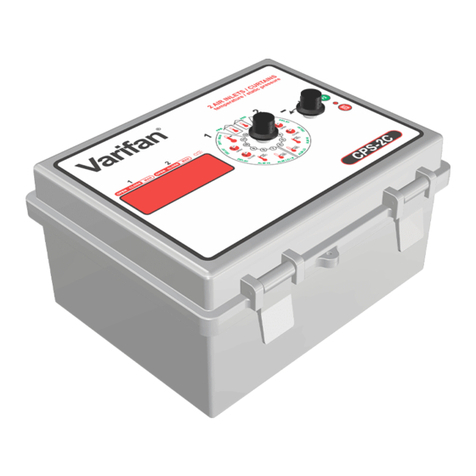
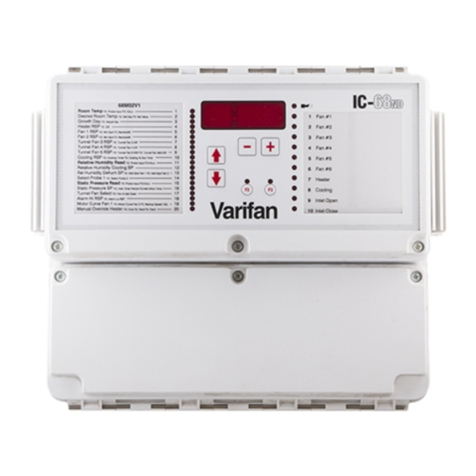
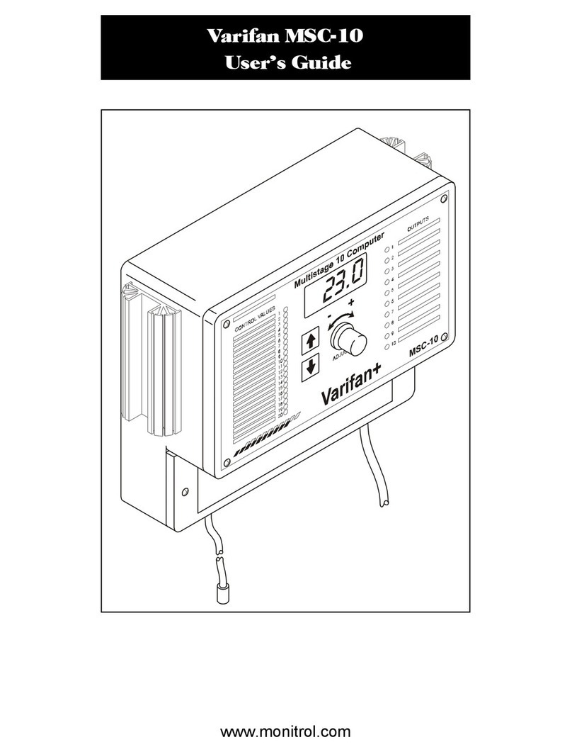
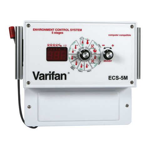
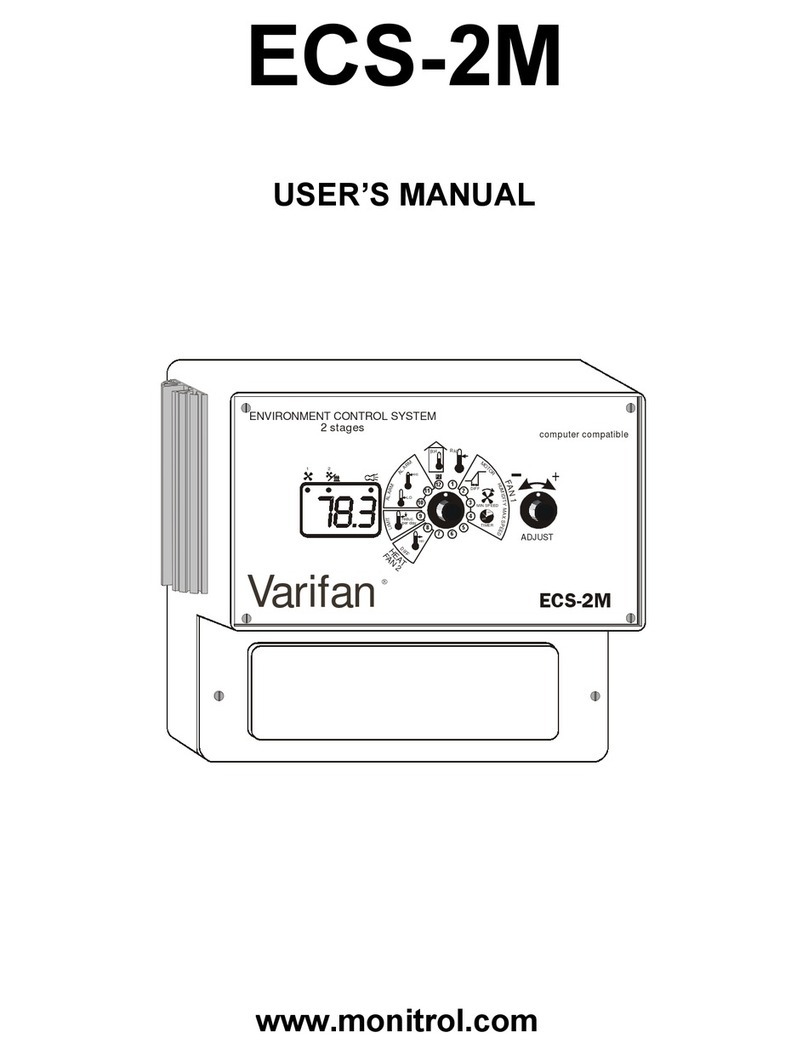
Varifan CPS-3M User manual

CPS-3M
USER’S MANUAL
www.monitrol.com

Page 2
CPS-3M
Although the manufacturer has made every effort to
ensure the accuracy of the information contained herein,
this document is subject to change without notice due to
ongoing product development.
WARNING AND PRECAUTIONS
Equipment, probe failure, blown fuses and/or tripped
breakers may prove harmful to the contents of the
building. Therefore it is strongly recommended to install
backup devices and alarm or warning devices. Spare
equipment should also be available at the owner’s site.
Equipment manufactured by the manufacturer is protected
against normal line surges. High surges caused by
thunder storms or power supply equipment may damage
this equipment. For added security against line voltage
surges, it is recommended that surge and noise
suppression devices be installed at the electrical
distribution panel. Use of shielded cable for probes is
recommended for protection against lightning. These
devices are available from most electrical supply
distributors.
RECOMMENDATIONS
The manufacturer recommends that all installation
procedures described herein be performed by a qualified
electrician or installation technician. Furthermore the
manufacturer recommends to test all the functions and
equipment connected to the CPS, including the alarm
system and backup devices, after installation, after
modifications, and once a month after that.
Fuse verification and replacement, as well as the proper
setting of control values, shall be the responsibility of the
owner of this equipment.
www.monitrol.com

Page 3
TABLE OF CONTENTS
CHAPTER 1 - INTRODUCTION
1. General ...........................................................................5
1.1 Description .......................................................................5
Definition of terms .........................................................................6
CHAPTER 2 - INSTALLATION
2.1 Unpacking ........................................................................7
2.2 Installation .......................................................................7
2.3 Switch Settings.................................................................8
2.3.1 Line Voltage Selector Switch ...........................................8
2.3.2 Software Setting DIP Switch ............................................8
2.4 Connection Procedure .....................................................9
2.4.1 Input Power ......................................................................9
2.4.1.1 115 VAC...........................................................................9
2.4.1.2 230 VAC...........................................................................9
2.4.2 Zone 1 Actuator Motor .....................................................9
2.4.3 Zone 2 Actuator Motor .....................................................9
2.5 Temperature Probe .........................................................10
2.5.1 2 Temperature Probes ....................................................10
2.5.2 Temperature Averaging ..................................................10
2.6 Alarm...............................................................................11
2.7 Powering Up....................................................................11
Fig.1 Wiring Diagram ...............................................................12
Fig.1a Wiring Diagram for a three phase motor .........................12
Fig.2 Wiring Diagram (probes) .................................................13
Fig 3 Connection Diagram (average) .......................................13
Fig.4 Electronic Card Diagram .................................................14
CHAPTER 3 - USER’S GUIDE
Faceplate ........................................................................15
LED Status Window ........................................................15
Control Dials....................................................................15
FUNCTION 1
Zone 2 Room Temperature Display ................................17
Zone 2 Main Set Point Temperature ...............................18
Zone 2 Maximum. Run Time...........................................19
Zone 2 Record High Temperature .................................20
Zone 2 Record Low Temperature ..................................21
Heating Set Point ............................................................22
Heating Differential..........................................................23
Palier 1 Affichage de la température (basse)..................24
Palier 1 Affichage de la température (haute) ..................25
www.monitrol.com

Page 4
CPS-3M
Zone 1 Record Low Temperature ..................................24
Zone 1 Record High Temperature .................................25
Zone 1 Max Run Time.....................................................26
Zone 1 Main Set PointTemperature ................................27
Zone 1 Room Temperature Display ................................28
FUNCTION 2
Zone 2 Differential...........................................................29
Zone 2 Delay Timer (actuator 2) .....................................30
Zone 2 High Temperature Alarm.....................................31
Zone 2 Low Temperature Alarm .....................................32
Zone 1 Low Temperature Alarm ....................................33
Zone 1 High Temperature Alarm.....................................34
Zone 1 Delay Timer (actuator 1) .....................................35
Zone 1 Differential...........................................................36
APPENDIX
Troubleshooting ..............................................................40
Specifications ..................................................................41
Record Form ...................................................................42
WARRANTY
www.monitrol.com

Page 5
1. GENERAL
This document provides you with the necessary
information to install and operate the CPS-3M. The
document is presented as follows:
•Introduction
•Installation
•User’s Guide
•Appendix
Congratulations on your purchase of a CPS-3M natural
ventilation system. With options such as motor activated
curtains and integrated heating units, this product is
designed to provide optimal temperature control in
ventilated buildings.
The CPS-3M controls natural ventilation, either
simultaneously on both sides with a single actuator, or
independantly on both sides with 2 actuators. Those
options can be selected from a dip switch, located behind
the electronic card, inside the faceplate.
Moreover, the CPS-3M is equiped with state of the art logic
for extra-accurate ventilation and heating control.
The present manual has been published in order to make
custom installation and control easier. Initially, the CPS-3M
was designed for 3-wire actuators. If, however, four-wire
actuators are used, external relays will have to be installed
according to the wiring diagram (fig. 5) on page 14. Before
choosing any type of relay, make sure to consult the
specifications table (p. 41) of this manual. It contains the
minimum load information for CPS-3M’s relays.
CHAPTER 1 - INTRODUCTION
www.monitrol.com

Page 6
CPS-3M
DEFINITION OF TERMS
TEMPERATURE MAIN SET POINT
The desired temperature in a room.
ROOM TEMPERATURE
The actual room temperature
AIR INLET/ CURTAIN
A device which regulates airflow into a building by
controlling the opening or closing of an air passage.
www.monitrol.com

Page 7
Chapter 2 describes the installation of the CPS-3M control.
2.1 UNPACKING
Unpack the CPS-3M from its box and inspect contents for
damage. Should the contents appear to be damaged,
contact your local distributor to return the material .
The package should contain the following standard items:
•1 CPS-3M control
•3 cable fasteners
•2 temperature probes
The following optional items may be included:
•3 additional temperature probes per zone for
temperature averaging.
2.2 MOUNTING
Use a screwdriver to remove the faceplate and the plate on
the power compartment.
Mounting hardware is not included.
CHAPTER 2 - INSTALLATION
The manufacturer recommends that the installation
instructions which follow be adhered to as closely as
possible, and all work be performed by a certified
electrician. Failure to do so may void the warranty!
To limit the unit’s exposure to noxious gases install the
unit in a hallway.
Make sure the unit is properly installed, that is, side up
with the cable entry holes facing down.
The CPS-3M will operate in a temperature range of 32°F
to 120°F (0°C to 50°C).
The enclosure is watertight, it is not splash proof or
immersion proof. DO NOT WATER the control. Cover it
carefully with plastic when cleaning the room.
www.monitrol.com

Page 8
CPS-3M
Once both faceplates are off, install the mounting screw on the wall
and install the unit on it. Use two more screws to secure the CPS-
3M in place using the bottom mounting holes.
2.3 SWITCH SETTING
The CPS-3M is configured for a variety of options via the
two following switches:
2.3.1 - Line Voltage Selector Switch
This switch is located on the surface of the main (bottom)
board and adapts the CPS-3M to 115 VAC or 230 VAC line
voltage.
See figure 1
2.3.2 - Software setting switch
This switch is located in the back of the CPS-3M faceplate
and regulates the following options:
1
2
3
4
Switch 1: Selects between a Fahrenheit or Celcius display
on the front panel.
Switch 2: Locks/unlocks user settings. Locked settings:
all settings are locked except for set points in positions (11)
and (2).Hi and Lo positions (8), (9) and (4) (5) can be
cleared in locked settings. Unlocked settings: all
parameters may be modified or cleared.
Switch 3: Selects the number of zones
Switch 4: Not used
230V
115V
OFF ON
Fahrenheit
Settings locked
1 zone
Not used
Celcius
Settings unlocked
2 zones
Not used
OFF ON
www.monitrol.com

Page 9
2.4 CONNECTION PROCEDURE
For the following connection procedures, refer to figures 1.
2.4.1 - Input power
Use a screwdriver to remove cable knock-outs for the
installation of cables on the CPS-3M.
2.4.1.1 - 115 VAC
Make sure that the line voltage selector switch is set to
115 VAC. See figure 1 for wiring.
2.4.1.2 - 230 VAC
Make certain that the line voltage selector switch is set to
230 VAC. See figure 1 for wiring.
2.4.2 - Zone 1 Actuator motor
Zone 1 provides two relays which control an actuator motor
connected to an air inlet. The first relay controls air inlet
opening and the second controls air inlet closing. The
current rating is 6 Amps (inductive).
See figure 1.
2.4.3 - Zone 2 Actuator motor
Zone 2 provides two relays which control an actuator motor
connected to an air inlet. The first relay controls air inlet
opening and the second controls air inlet closing. The
current rating is 6 Amps (inductive).
See figure 1.
2.4.4 - Wiring diagram for a three phase motor
See figure 1a
2.4.5. - Wiring diagram for a four wire motor
See figure 5
CHAPTER 2 - INSTALLATION
Do not power up the CPS-3M until all connections have
been completed!
www.monitrol.com

Page 10
CPS-3M
2.5 TEMPERATURE PROBES
Temperature probes use a “Class 2” low voltage circuit.
These cables can measure up to 500 feet (150 meters).
Probes longer than 10 feet (3 meters) must be shielded
with a #18AWG aluminum wire, or one bigger. The
shield must be connected to the CPS-3M’s SHLD
terminal.
The connections for 2 temperature probes are illustrated in
figure 2, whereas the connections for temperature
averaging are illustrated in figure 3.
2.5.1 2 Temperature probes
Install the temperature probes in the area that best reflects
the overall room temperature.
Connect both temperature probe leads and the shield to
the terminals labelled IN1 and IN2 (see figure 2).
2.5.2 Temperature averaging
•1 Zone: Four temperature probes are required to
perform temperature averaging in larger rooms
•2 Zones: Eight temperature probes are requiredto
perform temperature averaging in two rooms (4 per
zone)
To get superior readings, place the probes in locations that
best reflect room temperature (see figure 3).
www.monitrol.com

Page 11
2.6 ALARM
The CPS-3M provides a normally open and normally
closed dry contact for alarming low or high temperature
conditions. Moreover, this same contact can be used to
signal a power failiure. It may be connected to an alarm
system or directly to a siren and / or auto-dialer.
Make the normally closed (NC) or normally open (NO)
connections as indicated in figure 2.
2.7 POWERING UP
Before powering up the CPS-3M, attach the faceplate to
the casing of the CPS-3M using the six screws previously
removed.
Set Selector knob to position (12).
Upon power up, the unit will test its display by briefly
lighting up all the segments of its LEDs. Make sure all
segments light up.
Following the LED display test, the unit displays the room
temperature.
If the temperature is not displayed, refer to the Trouble
Shooting section of this manual.
CHAPTER 2 - INSTALLATION
Momentary power interruptions may trigger false alarms!
To avoid them, when the CPS-3M is connected to an
alarm system, install a time delay relay between the
CPS-3M and the alarm system.
www.monitrol.com

Page 12
CPS-3M
Figure 1 Wiring for 2 actuators and 1 heating unit
Figure 1a Wiring diagram for a three phase motor
WARNING!!!
SET LINE VOLTAGE
TO CORRECT VALUE BEFORE
ATTEMPTING TO OPERATE
THE CONTROL.
www.monitrol.com

Page 13
Figure 2 Temperature probes
Figure 3 Probe connection for temperature averaging in 1 zone
CHAPTER 2 - INSTALLATION
SHLD
OR
www.monitrol.com

Page 14
CPS-3M
Figure 4
Main (bottom) board: terminal blocks, switch and jumpers.
Figure 5
Four wire motor with parallel windings
www.monitrol.com

Page 15
CHAPTER 3 - USER’S GUIDE
The CPS-3M’s faceplate shown above features a LED
status window and two control dials which are
usedrespectively to select a function and select a setting.
LED Status Window
The LED status window features a 3 digit LED readouts
display of temperature in Fahrenheit or Celsius, and
programmable settings.
In addition, the LED status window displays the operational
status of zone 1 and 2 via 2 LEDS per zone(see above
picture). When illuminated, each LED indicates that the
actuator motor is operating. A fifth LED is for the heating
unit and a sixth one is for the Hi / LO temperature alarms.
Control Dials
The center dial is the selector dial and is used to select one
of the CPS-3M’s 12 primary or 8 secondary functions. The
dial to the right of the selector dial is the adjustor dial and is
used to adjust the setting of each function or to enter
secondary mode.
The 12 primary functions are:
•1 Zone 2 room temperature
•2 Zone 2 temperature main set point
•3 Zone 2 actuator max run time
www.monitrol.com

Page 16
CPS-3M
•4 Zone 2 record high temperature
•5 Zone 2 record low temperature
•6 Heating set point
•7 Heating differential
•8 Zone 1 record low temperature
•9 Zone 1 record high temperature
•10 Zone 1 actuator max. run time
•11 Zone 1 temperature main set point
•12 Zone 1 room temperature display
Any one of these primary functions is selected by rotating the
selector dial to the corresponding number and associated
graphic image on the faceplate. When a primary functions is
selected, the window displays a blinking value. Function 12
displays room temperature in zone 1 and function 1 displays
room temperature in zone 2.
The 8 secondary functions are:
•2 Zone 2 differential
•3 Zone 2 delay (actuator 2)
•4 Zone 2 high temperature realtive alarm
•5 Zone 2 low temperature relative alarm
•8 Zone 1 low temperature relative alarm
•9 Zone 1 high temperature relative alarm
•10 Zone 1 delay (actuator 1)
•11 Zone 1 differential
Select any one of these secondary functions by:
•rotating the selector dial to position (12)
•rapidly rotating the adjustor dial back and forth to enter
secondary mode.
•rotating the selector dial from function (12) to any other
secondary function.
When secondary functions (2) through (11) are selected, the
status window displays a blinking value along with a scrolling
LED display. Selection of function (12) switches the CPS-3M
back to primary mode.
www.monitrol.com

Page 17
ZONE 2 ROOM TEMPERATURE
DISPLAY
This position displays the actual room
temperature (zone 2). When monitoring only 1
zone, the displays shows three horizontal bars
for this position.
Room temperature is displayed to the nearest
0.1 degree from a minimum display of 42.0°F
(5.5°C) to a maximum display of 111°F (44.0°C).
If temperature is lower than 42.0°F, Lo is
displayed. If temperature is higher than 111°F,
Hi is displayed.
Viewing the room temperature:
•rotate the selector dial to position (1)
The room temperature for zone 2 is displayed on
the CPS-3M.
CHAPTER 3 - USER’S GUIDE
www.monitrol.com

Page 18
CPS-3M
ZONE 2 MAIN SET POINT TEMPERATURE
(MANUAL MODE)
The main set point establishes the target
temperature in the building. The main set point
temperature is adjusted in 0.5 degree increments
from a minimum setting of 42.0°F (5.5°C) to a
maximum setting of 111°F (44.0°C).
Adjusting the main set point temperature:
•rotate the selector dial to position (2),
•rotate the adjustor dial counterclockwise to
decrease the setting, and clockwise to increase
it.
The main set point temperature is displayed on the
CPS-3M.
Manual mode:
The actuator motor may be manually controlled by
adjusting the main set point to OPN or CLO,
thereby causing the air inlet to either remain fully
open or closed.
To open the air inlet:
•rotate the selector dial to position (2), then, the
adjustor dial counterclockwise to the minimum
setting, until the display shows OPN. At that
particular moment, the air inlet is opening.
To close the air inlet:
•rotate the selector dial to position (2), then, the
adjustor dial clockwise to the maximum setting,
until the display shows CLO. At that particular
moment, the air inlet is closing.
www.monitrol.com

Page 19
ZONE 2 MAXIMUM RUN TIME
The air inlet timer establishes the maximum period
of running time for the actuator’s motor, which
shouldn’t count for more than 25% of the inlet’s
total movement, according to the actuator’s
manufacturer.
The timer is adjusted in 1 second increments from
a minimum setting of 1 second to a maximum
setting of 4 minutes.
Adjusting the inlet timer:
•rotate the selector dial to position (3),
•rotate the adjustor dial counterclockwise to
decrease the setting, and clockwise to increase
it.
CHAPTER 3 - USER’S GUIDE
The CPS-3M automatically calculates a run time
according to temperature variations and the difference
between room temperature and the main set point.
Example:
The timer is set to 30 seconds. When the control
determines that the air inlet must open, the timer’s delay
set by primary function (3) must run until the end. Then
the actuator motor will operate for 30 seconds before
stopping.
www.monitrol.com

Page 20
CPS-3M
ZONE 2 RECORD HIGH
TEMPERATURE
This position displays the highest recorded
temperature since the last clear.
The record high temperature is rounded to the
nearest 0.5 degree from a minimum display of
42.0°F (5.5°C) to a maximum display of 111.0°
F (44.0°C). If a temperature higher than 111.0°
F is recorded, Hi is displayed.
Viewing the highest temperature recorded
in zone 2:
•rotate the selector dial to position (4)
Clearing the high temperature value:
•quickly rotate the adjustor dial
counterclockwise, then clockwise.
CLr will be briefly displayed on the CPS-3M
www.monitrol.com
Table of contents
Other Varifan Control System manuals

Varifan
Varifan MST-5C User manual

Varifan
Varifan DIP-1/115 Operation manual

Varifan
Varifan DIP-1C Operation manual

Varifan
Varifan MSC-10 User manual

Varifan
Varifan SVIM-1LE User manual

Varifan
Varifan ECS-4+ User manual

Varifan
Varifan MST-2B User manual

Varifan
Varifan CM10-2 User manual

Varifan
Varifan MVS-1C User manual

Varifan
Varifan VPM-1 User manual
Popular Control System manuals by other brands

rotork
rotork Paksan P3F Technical manual

Coelbo
Coelbo SPEEDMATIC SET ALT Installation and operating instructions

Paso
Paso PM2021-V Instructions for use

Velux
Velux KFX 110 Instructions for use

Siemens
Siemens POWERS HU 186 Technical instructions

AUTOTECH
AUTOTECH AT-8070-D Installation and programming manual