belinus GlasGlas Module User manual

1
Belinus GlasGlas Module
Installation Instructions

2
TABLE OF CONTENTS

3
BASIC INFORMATION
SYSTEM DESIGN
INSTALLATION
ELECTRICAL CONNECTION
MAINTENANCE
DISCLAIMER
1
2
3
4
5
6

4
BASIC INFORMATION1
1.2.9 Avoid moving the modules by pulling cables or the junction box.
1.2.10 Keep children away from modules during transportation and installation.
1.2.11 Avoid wearing metal rings, bracelet, earrings, nose rings, lip rings or any metal accessories during trans-
portation and installation of the modules. Do not touch electrical part of the modules by hand without any
insulated protection. Use insulated tools which satisfy electrical requirement to connect electrical parts of the
modules.
1.1 Preface Introduction
Thank you for choosing PV modules of Belinus Solar BV. The PV modules in this manual were manufactured
or sold by our company.
This manual contains the information of installation and safe operation of Belinus Solar BV’s Dual-glass PV
modules (hereafter referred to as “module”).
All instructions should be read carefully before installation. Please contact our sales department for more infor-
mation if you have any question.
The
installer
should
be
familiar
with
the
mechanical
and
electrical
requirement
of
PV
system.
The
installer
should comply with safety precautions listed in this manual and local law regulations when installing the mod-
ules.
According to IEC61730 standard, the safety class of solar module is class II; the re protection grade of solar
module is class A (refer to UL790).
1.2 Warnings
1.2.1 It requires specialized skills and knowledge for installation of solar photovoltaic systems. It should be op-
erated by professional installation personnel who have qualied licensed.
1.2.2 When the modules are exposed to sunlight or other light sources, DC current is generated in the modules.
At this time, if touching the electrical part of the modules, it may happen electric shock hazard.
1.2.3 The modules could be installed in outside environment, such as ground, roofs etc. If the modules are in-
stalled on the roof, the roof should have a certain re protection capability. It can consult the local construction
department to decide the roof material. Do not use this module to replace the whole or partial roofs/walls of
living buildings. The system designer or installer have responsible for reasonable support structure.
1.2.4 Do not disconnect any of the modules connecter during work.
1.2.5 Do not disassemble modules or move nameplate or any adhesion parts of modules.
1.2.6 Do not place the modules where it is easy to full of combustible gases.
1.2.7 Do not use Articially concentrated sunlight on the module. Do not expose the back of the module to sun-
light for a long time.
1.2.8 Avoid dropping or covering on the modules. Do not tread, stand or walk on modules, because there is a
risk of damage to the module and harm to person.

5
1.2.12 During transportation of the modules, please make sure that any impact and strenuous vibration should
be avoid. The impact and strenuous vibration have possible to lead cracks of solar cell in the modules. When
the modules arrive the destination, before installation, the module should be placed on the at ground with
protection which has ability to avoid moisture, wind, rain and snow. Please unpack carefully.
1.2.13 Avoid any damage of the glass of the module, which can protect the modules. Avoid any damage of the
seal on the edge of the modules. Without seal protection, the modules have risk of destroy. The damage mod-
ules have risk of electric shock or re. The damage module can’t be repaired. If there is any damage on the
modules, please replace the modules immediately.
1.2.14 In order to reduce the risk of electric shock or combustion, opaque material can be used to cover the
front surface of the modules during installation.
1.2.15 Installers should make sure rm connections between the rack and PV module without loose connec-
tions.
1.2.16 The frame and support of all modules should be grounded correctly, according to “National Electrical
Code”. The modules without frame have not leakage current between solar cell and insulation material. There-
fore, the modules without frame can be installed without grounded.
1.2.17 Do not clean the modules with corrosive chemicals.
1.2.18 It is possible to aect re resistance of the house if roof-mounted. According to IEC61730, the level of re
resistance of modules, which is installed on roof, is Class C (refer to UL790). For roof application, the estimate of
re control level of module system should combine module and roof condition. Only correct installation, which
accords to installation instruction, the re resistance of module system is eective.
1.2.19 During the storage, transportation, installation and maintenance of components, it is strictly prohibited
to contact with any form of oil stain or corrosive chemical reagent.
1.3 Product Identication
1.3.1 Each module has a label on the back, generally containing following information:
Product type, weight, size, fuse current, the system max voltage, rated power measured under standard test
conditions, rated current, rated voltage, open circuit voltage, short circuit current.
1.3.2 Bar code (serial number): each module is registered with a unique serial number. It is xed in the module
permanently. It can see the bar code in front of the module.
B E
X
X
X
X
X
X
-
X
X
X
X
X
X
The product number of each component
Represents the serial number of order
Month
Year
Manufcaturer
Represent Belinus Solar BV
Figure1 Bar Code
1.3.2.1 The unique bar code (serial number) of the module consists of 14 bits and a line. The rst eight digits of
serial number are composed of two manufacture codes, three date codes and three order serial Numbers. The
line is followed by six digit numbers of module production code. The number of module in each order will not
exceed 999999.
BE X
X
X
X
X
X
X
-
X
X
X
X
X
X

6
The product number of each component
Represents the serial number of order
Month
Year
Manufcature
Represent Lianyungang Shenzhou energy Co. Ltd
Tilt
Module
Sunlight
Horizontal line
Figure 2 PV module tilt angle
2.2.5 The modules should be installed in the position where is full of sun exposure without shadow at any time.
2.2.6 Generally, it is not recommended to be installed in the place where is less than 500 meters from the sea.
The modules, as a general rule, can guarantee 25 years of useful life if the module is installed in the place where
is more than 3 km from the sea. If the module is installed in the place where is 500-3000m to the sea, the mod-
ules need extra protection. (For example, increasing the thickness of the oxide lm of Aluminum metal alloy
frame, and increasing the anti-corrosion treatment of frame connection.)
2.2.7 When a storage battery is used in the photovoltaic system, the battery must be installed correctly. There-
fore, it can protect the safety of photovoltaic system. The installation of the storage battery should follow the
instructions of storage battery manufacturer.
2.2.8 It is recommended that the height of the module is 0.3-1m higher than actual environment.
2.3 Installation Inclination Angle Selection
2.3.1 PV modules connected in series should be installed in the same orientation and angle.
2.3.2 If connected to an independent photovoltaic system, the installation angle of the module should be based
on the season and light conditions to achieve the maximum power output. At the lowest illumination intensity,
if the power generated by module with certain angle can satisfy the lowest power generation, it is think that the
modules with the certain angle can satisfy the power generation all year around. For grid-connected system, the
installation angle of modules depends on the max power generation all year around.
2.4 Choose the Photovoltaic Support
The system designer or installer have responsible for calculation the system load to make sure all module can
support the estimated load. The module support manufactures should supply qualitied module supports. The
support, which is used for photovoltaic system, should has the third test institution certication about static
2.1 Climatic Conditions
2.1.1 Relative humidity: < 85%.
2.1.2 The operating temperature of the module is - 40 ℃ - 85 ℃.
Note:When calculating the mechanical load of components (including the pressure of wind and snow), the in-
stallation method and installation site should be considered. The calculation of mechanical load must be carried
out by professional personnel according to the design requirements of the system.
2.2 Location Selection
SYSTEM DESIGN2
2.2.1 The maximum altitude for Belinus PV module is 2000m.
2.2.2 At standard test conditions (1000W / m² irradiance, AM 1.5 spectrum, 25 ° C (77 ° F) ambient temperature),
the test error of module electrical performance parameters of modules, such as Isc, Voc, and Pmax, is ±3% for
Pmax and ±5% for Voc and Isc.
2.2.3 In the northern hemisphere, it advises that the modules face to south direction. In the southern hemi-
sphere, it advises that modules face to north direction.
2.2.4 The tilt angle of the PV module is the angle between the surface of the PV module and a horizontal ground
surface (as shows in Figure 2). The PV module generates maximum output power when it faces the sun vertical-
ly. It is recommended that the installation angle of the module is bigger than 10 degrees. If you want the specic
information of the best install tilt angle, please consult reliable local photovoltaic system installation companies.

7
The product number of each component
Represents the serial number of order
Month
Year
Manufcature
Represent Lianyungang Shenzhou energy Co. Ltd
mechanical analysis ability.
2.4.1 Installation of bifacial module without shading the back of module
When designing the modules’ support structure, the support components cannot cross the module cell area.
The support components can be set up at the edge of the module. At the same time, the inverter should be
installed at the side of the module instead of back. If the inverter is installed at the back of the module, it may
reduce the reected light and reduce power generation of the back of the module.
Vmax - Maximum system voltage
Voc - Open circuit voltage of each module(refer to product label or data sheet).
Tc(voc) - Thermal coecient of open circuit voltage for the module(refer to data sheet).
Tmin - The lowest ambient temperature.
Figure 3 The component bracket does not cover the back module
2.5 Choosing the Photovoltaic Inverter
When choosing photovoltaic inverter, it needs consider the power, open-circuit voltage, short-circuit current of
PV modules array. The minimum voltage of the module array should be higher than the threshold voltage of
inverters to guarantee the inverters regular work.
2.5.1 Calculation of modules’ number in series array
Please use the suitable equipment, connectors, wires and rack which match with solar power system. Please
make sure the type of the modules is same in a single PV system. When determining rated voltage, wire ca-
pacity, fuse, the controller capacity and module output power of relevant parts of PV system, please accord to
the short-circuit current (Isc) and open circuit voltage (Voc) showing on modules’ label to determine suitable
parameters.
In normal outdoor conditions, the current and voltage generated by module may be dierent from the param-
eters listed in Table. The parameter list in table is measured under standard test conditions (STC). In dierent
outside climate surrounding, because of dierent power generation coecient, the actual parameters, includ-
ing rated voltage, wire capacity, fuse, the controller capacity and module power output, is dierent if modules
working in dierent area. In order to get the actual module’s electrical parameters, usually,the photovoltaic sys-
tem designers or installers can use short-circuit current (Isc) and open circuit voltage (Voc) noted on modules’
label multiply by 1.25 (redundant value). If the bifacial modules are installed at high reective surrounding, the
redundant value can increase suitably.
Please make sure the system voltage of each modules’ array is lower than the maximum voltage of photovoltaic
system, rated voltaic of inverter and controller. The system current of each modules’ array is less than maxi-
mum current of photovoltaic system, rated current of inverter and controller.
The connection of modules: According to the system requirement of output voltage and current, modules are
connected in series or parallel. The maximum number of modules in series (N) is equal to the number of the
maximum system voltage (Vmax) divided by the open circuit voltage (Voc) of each module. The number of mod-
ules in parallel has relate to the parameters of electrical equipment (such as inverter and controller) in STC.
N - Number of modules in series.

8
String 1
String 1
String 2
String 2
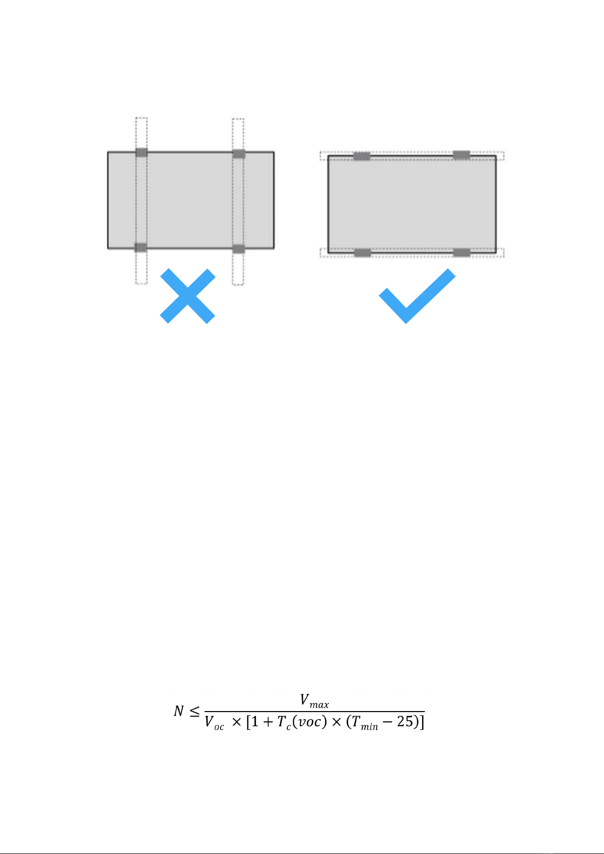
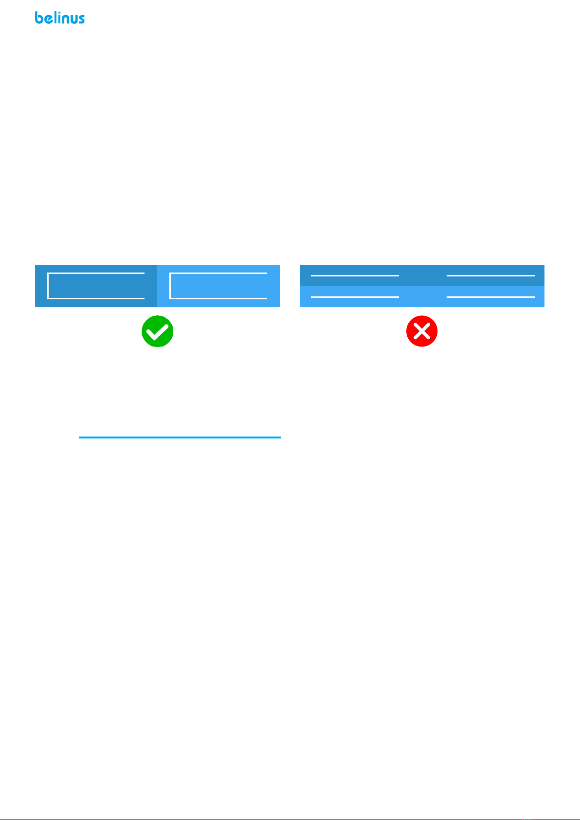
2.6 Bifacial Module Arrangement and Layout Optimization
Generally, for normal modules’ array, there are 2 methods of module connection. The rst method connects
the upper module and the under module in series. The second method separates the upper and the under
modules. All upper modules connect in series, and all under modules connect in series separately. There is sig-
nicant height dierence between upper and under modules. The signicant height dierence lead to light illu-
mination dierence between upper and under modules. The light illumination dierence lead dierent working
current of the module. If choosing the rst method, the under module, which has lower working current, will
decrease the working current of the upper module. The decreasing of upper modules’ working current will
reduce the whole power generation of photovoltaic system. When choosing the second method, the upper
modules and the under modules have dierent working current. It can decrease power loss due to working
current mismatch, which improves the advantage of bifacial modules and increases whole power generation of
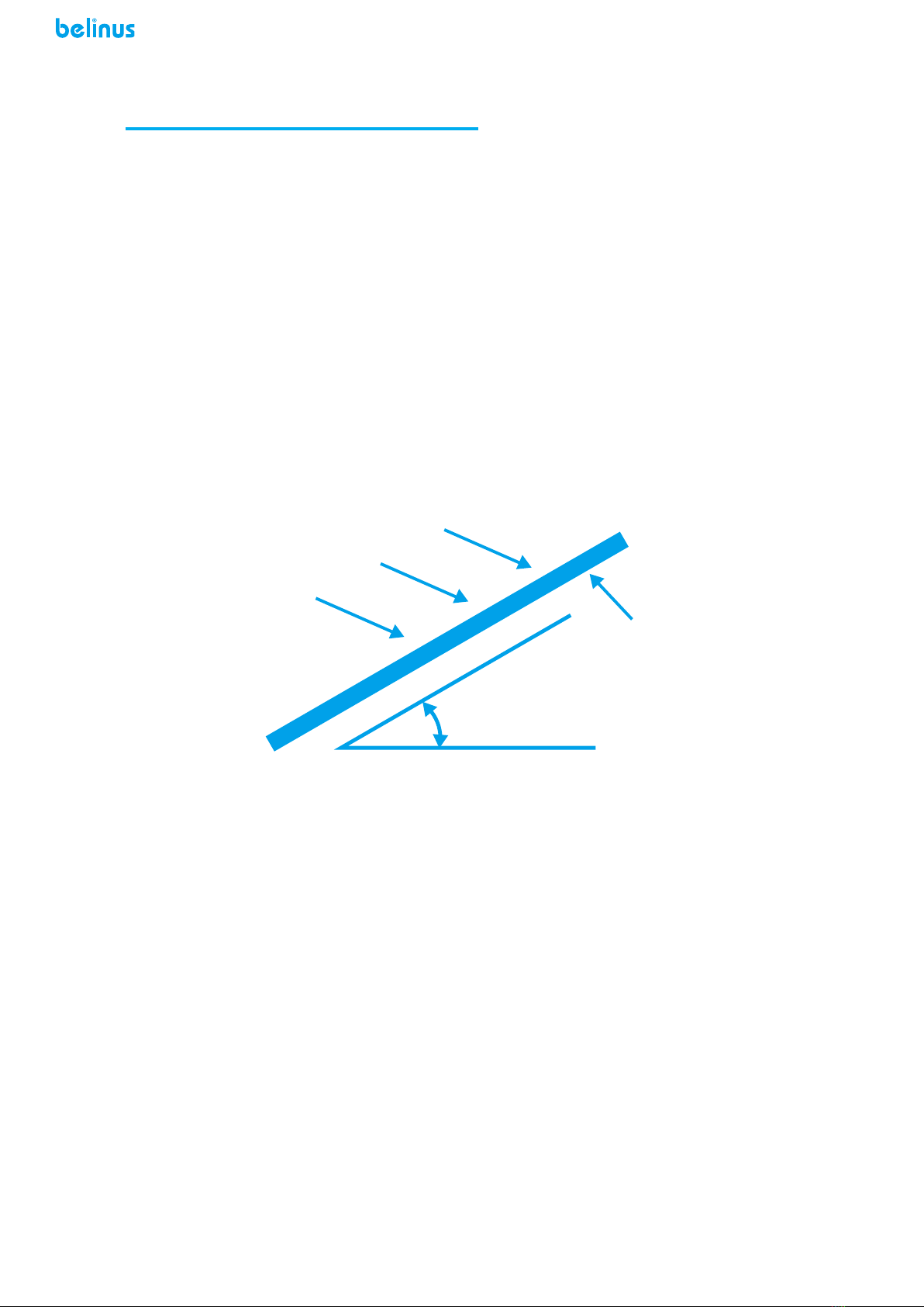
photovoltaic system. The light illumination rises with height increasing at the same outside surrounding. There-
fore, the upper modules have higher light illumination than the under modules. In order to declining the current
mismatch, we advise the second modules connection method. At the same time, please connect the upper/un-
der modules’ array to the dierent MPPTs of the inverter individually. This is the best method of modules’ array
connection for photovoltaic system.
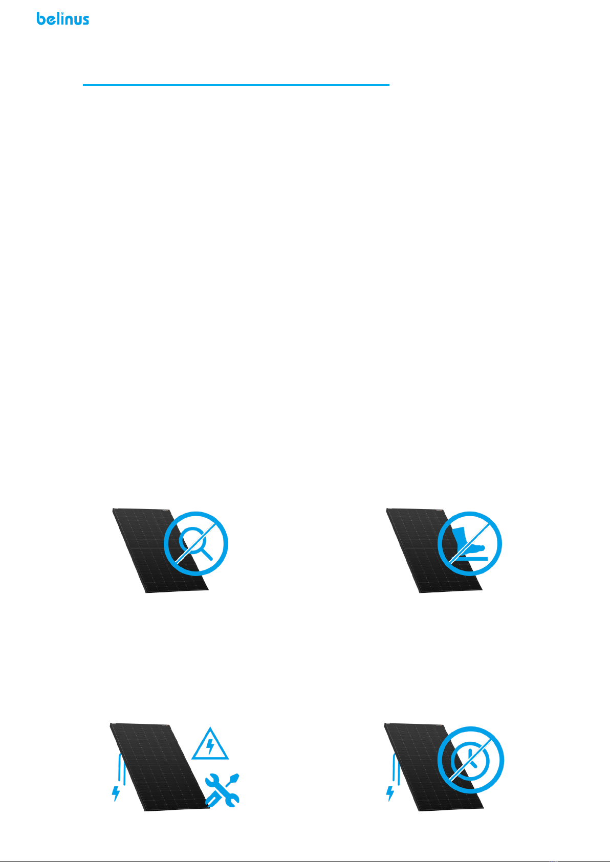
3.1 Installation Safety
3.1.1 Wear protective headgear, insulating gloves and rubber shoes when modules are installed.
3.1.2 During installation, avoid standing on the modules, which will lead to damage of modules, or hazard hu-
man safety. Avoid unnecessary touching of modules. The surface and frame of modules may be very hot, which
may lead to burn or electric shock.
3.1.3 Don’t unpack the outside packing of modules except to install immediately. Avoid installing in rainy, snowy
or windy weather.
3.1.4 In order to reduce hazard of electric shock, if the junction box connecters are wet, stop installing.
3.1.5 During installing, do not throw anything, including modules and installation tools.
3.1.6 Please make sure connecting junction box correctly. Checking wiring status to ensure that all strong con-
nection without broken. Take adequate measure to avoid any scratch which may damage the cables or pressure
which may damage the module.
3.1.7 During installation or sunshine, avoid touching the junction boxes or connectors no matter what the mod-
ules are connecting with photovoltaic system or not.
3.1.8 Avoid pressing or putting something heavy on the module’s surface or distorting the module’s frame.
3.1.9 Avoid setting overweight things or hitting on the module’s surface glass, which may lead damage or micro-
crack of the solar cell.
3.1.10 Avoid cleaning the modules with sharp tools, which may lead to scratch on the surface of modules.
3.1.11 Avoid digging holes on the module’s frame without permission.
3.1.12 For BIPV or roof application, please installing in plan. Please follow the installation rules of “from top to
bottom” or / and “from left to right” as much as possible.
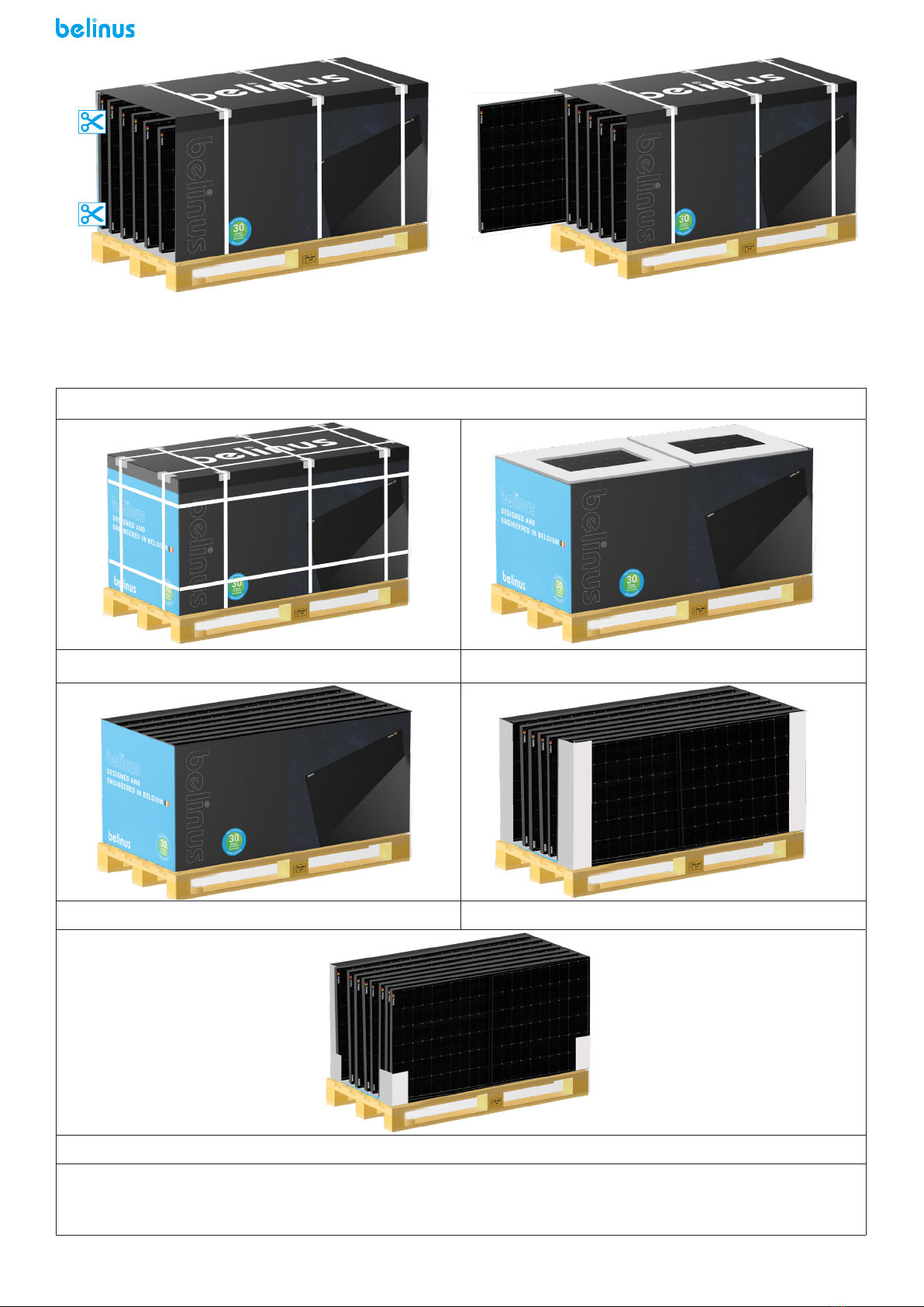
3.2 Modules Unpacking
3.2.1 When the modules arrival to destination, avoid unpacking modules in humid and rainy weather.
3.2.2 After unpacking, the modules should be placed horizontally. Avoid tilt, pressure, leaning on the wall of the
modules.
Figure 4 Optimization of modules’ array connection
INSTALLATION3

9
BiFi Module
BiFi Module
Support Weight
BiFi Module
Support
3.2.3 The modules of two batches are separated and stacked neatly. If the dual-glass modules with aluminum
frame need to stack, the weight of modules’ stack should not exceed 20kg. The number of modules per stack
is less than 24pcs. If the weight of dual-glass modules (with frame) exceeds 20kg, the number of modules per
stack is less than 20pcs.
If the dual-glass modules without aluminum frame need to stack, the modules should be place on a horizontal
pallet. The modules without aluminum frame should be placed horizontally. The number of modules in each
stack is ≤10pcs. The duration of each stack ≤5 day. Use cushioning material to separate each module (without
frame). The thickness of cushioning material is 10mm thicker than the shortest distance between 2 modules,
such as the distance between junction box/back hooks to the adjacent module. It recommends to use EPE,
which density higher than 28kg/m³, as cushioning material. The cushioning materials set 6 scattered points.
During stack of modules without aluminum frame, keep the thickness of cushioning material homogenerous
avoiding bending of modules. If the modules bend during stack, please adjusting the thickness of cushioning
material. If there is not suitable cushioning material, please avoiding stack of modules without aluminum frame.
Module with frame unpacking paper boxes process
1.Do not remove the 3 packing belts indicated by the
arrow, and remove the other packing belts of the
package.
2.Remove one side of the package (shaded part).
No tilting No stacking No leaning
Figure 5 Modules stack illustration
3.2.4 Unpacking process should follow the instructions as the gure below. Avoid rude operation or using crow-
bar to open the boxes. Pay attention to person and modules safety during unpacking.
3.2.5 After unloading, the modules’ box should be placed on dry and at ground, without wet, muddy and un-
even ground condition.
3.2.6 After arriving the destination, the upper and lower modules’ boxes should be separated and placed sepa-
rately without stack. If the modules cannot be installed immediately, it should be care to protect the package of
modules’ boxes. Avoid any packing damage from natural disasters such as rain, snow, hail, typhoon, etc.
3.2.7 The front glass of the outermost two components of the dual-glass belt frame component faces the inner
wall of the carton. Pay attention to protect the modules from accidental damage during loading, unloading and
unpacking.

10
Module without frame unpacking paper boxes process
1.Remove the packing belt by tools. 2.Dismantle the box cover.
3.Remove the lifting brackets and the cover 4.Remove the coaming.
5.Remove the packing belt and side liner.
Note: there may be some dierences in the accessories of dierent models of module packing boxes, such
as the number of packing belts and the number of inner lining strips, etc., which shall be subject to the actu-
al arrival.
Figure 6 Module with frame unpacking process
3.Cut the two horizontal packing belts in the carton. 4.Disassembly modules from side. According actual
surrounding, avoid tipping over or sliding of unpack-
ing modules.
Figure 7 Module without frame unpacking process

11
3.3 Introduction of Installation Method
The modules can be installed in the following methods: clamp installation and bolt installation.
3.3.1 All installation methods described in this instruction are only for reference. Our company is not responsi-
ble for providing relevant installation parts, design and installation of component system. Mechanical loading
and safety should be nished by a professional photovoltaic system installer or PV system technicians.
3.3.2 Before installation, it is necessary to check than if there is any defects or other foreign matter which is
related with appearance and the safety performance of the junction box. If there is any problem, please solve
the problem.
b) Please make sure that the serial number of the module is correct.
3.3.3 If the modules are installed in harsh environments, such as snowy or windy, extra measures are needed
to protect the modules.
3.4 Installation of Clamps Module with Frame
It suggests to use M8 bolts for module installation. The clamp or belt used for module installation should over-
lap the aluminium frame. The width of overlap is between 7 mm (0.28 in) to 10 mm (0.39 in). All the installation
methods described here are only for reference. We are not responsible for the design of installation part and
photovoltaic system installation. Mechanical load and safety of photovoltaic system must be performed by a
professional system installer or someone with special certication.
• Use more than 4 clamps to x modules on the support.
• Modules’ clamps, which used for module installation, can’t shadow the front surface
glass and distort module’s frame.
• Avoid shadow on the surface of modules.
• The module frame is not to be modied under any circumstances.
When choosing this type of clamp-mounting method, each module needs 4 clamps at least. Depending on local
weather, such as wind and snow condition, additional clamps may be required to ensure that modules have
enough support. (In case of severe environment such as storm and heavy snow, it is recommended to use extra
clamps for installation. Please contact with our technical support for further information.)
• Applied torque should consider mechanical design standard which accords to the bolt used by customer. e.g:
M8 ---- 16-20 N•m.
The safety factor of mechanical load is 1.5 times.
Component payload = design load * mechanical load safety factor multiple (1.5)
Method 1:
Installation of long side pressing block, design load≤2400Pa (front),1600 Pa (back)
(Use 4 clamps- length of blocks≥50mm)
NO. L*W(mm)
1 1658*992
2 1984*992
3 1686*1008
4 2009*1008
5 1704*1008
6 2031*1008
7 1791*1052
8 2131*1052
9 1755*1038
10 2094*1038
11 1730*1134
12 1915*1134
13 2100*1134
Notes:
1.L is the length of PV module. W is the wide of module. The black shadow is the area of installation.
2. The safety factor of mechanical load is 1.5 times.

12
Method2:
Installation of long side pressing block, design load≤3600Pa(front)2400 Pa (back)
(Use 6 clamps- length of blocks≥50mm)
NO. L*W(mm)
1 1658*992
2 1984*992
3 1686*1008
4 2009*1008
5 1704*1008
6 2031*1008
7 1791*1052
8 2131*1052
9 1755*1038
10 2094*1038
11 1730*1134
12 1915*1134
13 2100*1134
Notes:
1. L is the length of PV module. W is the wide of module. The black shadow is the area of installation.
2. The safety factor of mechanical load is 1.5 times.
Method 3 (18X module, 72 and 78 board type:
Installation of long side pressure block , design load ≤2400 Pa(front),1600 Pa (back)
(Use 6 clamps- length of blocks≥50mm)
NO. L*W(mm)
1 2285*1134
2 2470*1134
Notes:
1. L is the length of PV module. W is the wide of module. The black shadow is the area of installation.
2. The safety factor of mechanical load is 1.5 times.
Method 4 (18X module, 72 and 78 board type):
Installation of long side pressure block , design load ≤3600 Pa(front),2400 Pa (back)
(Use 8clamps- length of blocks≥50mm)

13
NO. L*W(mm)
1 2285*1134
2 2470*1134
Notes:
1.L is the length of PV module. W is the wide of module. The black shadow is the area of installation.
2. The safety factor of mechanical load is 1.5 times.
End clamp installation(30/35/40mm optional) Middle clamp installation
PV module installed with clamp tting method.
3.5 Installation of Clamps (Module without Frame)
The modules shall be installed by pressing blocks, which should cooperate with c-shaped steel. See gures be-
low: schematic diagram of pressing blocks installation.
Double-side briquetting illustration One-side briquetting illustration
Please ensure there is not shadow on the surface of module due to installation blocks. After deciding installation
method, please make sure than each module has 4 or 6 blocks and each long side of module has 2 or 3 blocks.
The number of blocks used depends on the local wind and snow pressure intensity. If the pressure exceeds the
expected estimated value, additional blocks or brackets are required to ensure that the modules can bear the
load. The torque of bolts should large enough for strength connect. The torque of bolts is 16-20N•m. The safety
factor is 1.5 times of the design value: component payload = design load * mechanical load safety factor multiple

14
(1.5), as shown in the table below.
Method 1:
Installation of long side pressing block, design load≤2400Pa (front),1600 Pa (back)
(use 4 pressing blocks - length of pressing blocks 150mm)
NO. L*W(mm)
1 1658*992
2 1978*992
3 1680*1002
4 2002*1002
5 1698*1002
6 2024*1002
7 1785*1046
8 2125*1046
9 1749*1032
10 2088*1032
Note:
1. L is the length of PV module. W is the wide of module. The black shadow is the area of installation.
2. The safety factor of mechanical load is 1.5 times.
Method 2:
Installation of long side pressing block, design load≤3600Pa(front),2400 Pa (back)
(use 6 blocks - length of blocks 200mm)
NO. L*W(mm)
1 1658*992
2 1978*992
3 1680*1002
4 2002*1002
5 1698*1002
6 2024*1002
7 1785*1046
8 2125*1046
9 1749*1032
10 2088*1032
1. L is the length of PV module. W is the wide of module. The black shadow is the area of installation.
2. The safety factor of mechanical load is 1.5 times.

15
Installation process:
The rst step: Install photovoltaic module blocks schematic diagram
Put the blocks into the rail bracket
The second step: Installation of photovoltaic modules schematic diagram
Place the PV module into the blocks as required and
tighten it
3.6 Installation of Bolts (Module with Frame)
The frame of each module has several 14 × 9mm mounting holes. Ideally, the position of holes have ability to
optimize the load distribution, to achieve great and strong module support structure.
In order to extend the life of module support, we advise to use anti-corrosion bolts or clamps (stainless steel)
strongly.
Use M8 bolt and at washer, spring washer and nut as shown in Figure 7 in each block. Tighten the bolts until
the torque reaching 16-20 N•m.
Figure 7. SPV module installed with Bolt tting method

16
1. Aluminum Frame
2. M8 Stainless bolt
3. Flat Stainless Washer
4. Spring Stainless Washer
5. HEX Stainless Nut
Installation of Bolts
NO. L*W(mm)
Design Load≤1600Pa(front),
1200 Pa (back)
Design Load≤3600Pa (front), 2400 Pa
(back)
Use 4 installation holes with S or P
holes
Use 8 installation holes with S and P
holes
1 1658*992
2 1984*992
3 1686*1008
4 2009*1008
5 1704*1008
6 2031*1008
7 1791*1052
8 2131*1052
9 1755*1038
10 2094*1038
11 1730*1134
12 1915*1134
13 2100*1134
14 2285*1134
15 2470*1134
3.7 Installation of Single-axis Tracking System (Module with Frame)
In some special type of modules, there are installation holes on the frame, which use for installation of sin-
gle-axis tracking system. These installation holes, including normal holes and single-axis tracking holes, is good
for press distribution and achieve strong support structure. With help of installation holes on the aluminium
frame of the module, bolts can be used to connect module and support. The detail of installation is showed
in follow gure. Use M6 bolt and a at washer, spring washer and nut for connection between modules and
supports. Tighten the bolts until the torque reach 16-20N.m (0.63-0.79 inches). The modules connected with
single-axis tracking system needs special stainless steel washers with a minimum thickness of 1.5mm and an
external diameter of 16-20mm (0.63-0.79 inches). In these install method, the maximum design load of the front
is 1200pa, the design load of the back is 1200pa, and the safety factor is 1.5 times. Component payload = design
load * mechanical load safety factor multiple (1.5).

17
Figure 8 Installation diagram of module with single-axis tracking system
4.1 Precautions for Electrical Connection
4.1.1 Please read the electrical wiring drawings carefully before wiring. The wiring should accord to local law
and program and be operated by certicated electricians. The maximum voltage of the system must be lower
than the maximum certied voltage and the maximum input voltage of the inverter and other electrical devices
installed in the system.
4.1.2 4.1.2 The connection between module and junction box: the module is connected with junction box by the
dc cable. The cross-sectional area of cable and the connector capacity must be satised with the system’s short
circuit current.The cable’s cross-sectional area for a single module is recommended to be 4mm2. The fuse cur-
rent and the rated current of the connector should be higher than 20A(18X series module s and double-sided
modules should be ≥ 25A). Otherwise, the cables and connectors will overheat due to high current. Please note
that the highest temperature of cable is 90 OC, and the highest temperature of connector is 125 OC.
4.1.3 The aluminum frame and support of the module must be grounded, as shown in Figure 9. Each module has
a grounding hole and is marked on the frame (it is recommended that the series / parallel connection of each
module must be grounded once). The installation method of grounding bolt is shown in FIG. 10. The grounding
wire and frame can be reliably grounded by the prepared grounding hole. And the at washers, spring washers
and nuts are matched by installing bolts M5 × 10 ~ 15. The modules and the earth wire shall be perfectly con-
nected by connecting plugs. Negative grounding inverter can be installed to prevent PID phenomenon.
ELECTRICAL CONNECTION4
Figure 9 Module grounding circuit Figure 10 Installation diagram of grounding bolt

18
4.1.4 Common hardware parts, such as nuts, bolts, star washers, lock washers, at washers, are used for ground-
ing/connecting. The installation of such hardware parts should comply with instructions of manufacturers.
4.1.5 The common grounding parts, such as nuts, bolts, star washers, lock washers, which have not been eval-
uated for electrical conductivity, are only to use for mechanical connection. And the grounding parts of the
module should keep suitable conductivity. These grounding parts, which supply the evaluation of UL 1703 as the
same as modules, can use for module’s installation according to installation instruction.
4.1.6 The electrical connection shall conform to local electrical laws and regulations. Avoid “Y” type electrical
connection mode in module system electrical connection.
4.1.7 Modules are equipped with bypass diodes (rated voltage 45V, rated current 25A). The improper installation
may damage diodes, cables or junction box.
4.1.8 If the modules unpack without installation immediately, please protect module connectors in order to
avoid damage due to wind or rain. Avoid lubricant on module’s connectors, because it may lead fail of connec-
tors.
4.1.9 Avoid removing the waterproof rubber rings out from the junction box or connectors.
4.1.10 Avoid using diesel oil to keep warm in installation site, because the gas generated by diesel oil or other
petroleum products may destroy module’s connector.
4.1.11The minimum bending radius cables should be 43mm (1.69in).
4.2 Wiring and Connections
4.2.1 When the long side of module is perpendicular to the ground, if there is only a row of modules, the cables
which connect adjacent modules can be short. If there are two row modules, which long sides are perpendicular
to ground, it needs a special jump cable to connect up and down modules. Please do not ignore the jump cable
during 2 row modules system design. Generally,the standard wire length of 60 plate type integrated junction
box is 0.9m. The standard wire length of 72 plate type junction box is 1.1m. If the module has separated junction
boxes, the standard wire length of each separated junction box is 0.2m (positive) and 0.3m (negative) respec-
tively. The wire length of other large-size plate and special plate components shall be subject to the correspond-
ing product parameter manual.
Junction box position style 1 Junction box position style 2 Junction box position style 3
Single row installation with long side of modules perpendicular to the ground
Two row module installation

19
MAINTENANCE5
The modules need to be inspected and maintained regularly, including visual inspection and all electrical con-
nections to ensure that there is stable connection without any broken.
• Check the open circuit voltage of each module:
• Cover the front surface of modules with an opaque material. There is hazard voltage if modules ex-
posed in light illumination.
• Disconnect the wires from both sides of the module.
• Remove the non-transparent material o the modules; check and measure the open circuit voltage of
the modules.
• If the measured voltage is reduced by 1/4, it supposed to be bypass diode damaged. Please test the
bypass diode performance.
• It’s recommend that adopt the following maintenance to ensure the modules maintain the best perfor-
mance:
Check whether the modules have any appearance defect: such as surface damage, abnormal or shadow. Make
sure that the module support system is stable without any loose part. If nding any abnormal situation, please
contact professionals to adjust or repair.
• Clean modules at least one time each year, depending on local conditions. If the surface of the module
becomes dirty, the power generation of the modules reduces. In this situation, you can use soft sponge or wa-
ter to clean the surface glass of the module. Mild, non-abrasive chemical cleaners can be used to help washing
modules. Avoid using any corrosion chemical cleaners. In order to reduce electric shock or burns, it is recom-
mended to clean modules in the morning or evening.
• Check mechanical and electrical property of modules every six months to ensure the modules’ connec-
tors clean and reliable. And ensure good electrical connection and no corrosion.
• If you have any questions, please contact with professionals and arrange further check.
• Please note that all maintenance instructions, such as brackets, charging rectier, inverters and batter-
ies, should be complied.
Two row module installation with long side parallel to the ground
• Meaning of crossed –out wheeled dustbin:
Do not dispose of electrical appliances as unsorted municipal waste, use separate collection facilities.
Contact your local government for information regarding the collection systems available.
If electrical appliances are disposed of in landlls or dumps, hazardous substances can leak into the groundwa-
ter and get into the food chain, damaging your health and well-being.
When replacing old appliances with new ones, the retailer is legally obligated to take back your old appliance
for disposals.

20
DISCLAIMER6
Because the use of the manual and the conditions or methods of installation, operation, use and maintenance
of photovoltaic (PV) product are beyond the control of Belinus Solar BV. We do not accept responsibility and
expressly disclaims liability for loss, damage, or expense arising out of or in any way connected with such
installation, operation, use or maintenance.
No responsibility is assumed by Belinus Solar BV for any infringement of patents or other rights of third
parties, which may result from use of the PV product. NO license is granted by implication or otherwise under
any patent or patent rights.
The information in this manual is based on our knowledge and experience and is believed to be reliable, but
such information including product specication (without limitations) and suggestions do not constitute a war-
ranty, expresses or implied. We reserve the right to change the manual, the PV produce, the specications, or
product information sheets without prior notice.
Table of contents