Altinex Tilt N Plug TNP510 User manual

TNP51
TNP51TNP51
TNP510/512
0/512 0/512
0/512 Tilt ‘N Plug
Tilt ‘N PlugTilt ‘N Plug
Tilt ‘N Plug
®
User’s Guide
400-0521-001
1
Welcome!
We greatly appreciate your purchase of the Tilt ‘N Plug. We are sure you will
fin it reliable an simple to use. Superior performance for the right price,
backe by soli technical an customer support is what ALTINEX has to
offer.
We are committe to provi ing our customers with
Signal Management Solutions
®
to the most eman ing au iovisual
installations at very competitive pricing an we welcome you to join the
ranks of our many satisfie customers throughout the worl .
1. Precautions and Safety Warnings
Please rea this manual carefully before using your TNP510/TNP512
Interconnect. Keep this manual han y for future reference. These safety
instructions are to ensure the long life of your TNP510/TNP512 an to
prevent fire an shock hazar s. Please rea them carefully an hee all
warnings.
1.1 General
•Qualifie ALTINEX service personnel or their authorize
representatives must perform all service.
1.2 Installation Precautions
•For best results, place the TNP510/TNP512 Interconnect Box in a ry
area away from ust.
•To prevent fire or shock, o not expose this unit to water or moisture.
Do not place it in irect sunlight, near heaters or heat-ra iating
appliances, or near any liqui . Exposure to irect sunlight, smoke, or
steam can harm internal components.
•Han le the unit carefully. Dropping or jarring can amage the bezel.
•Never place fingers insi e the opening on either si e of the unit. This
action coul cause injury ue to sharp e ges insi e.
•Do not place heavy objects on top of the TNP510/TNP512. Do not use
excessive force to push own on the top of the unit.
•Disconnect the
power cor to turn off the main power. This supplies
power to the power socket on the pop-up panel. The power outlet
shoul be installe near the equipment an shoul be easily accessible.
•We recommen using wall outlets with a Groun Fault Circuit
Interrupter (GFCI) for maximum protection.
•Install all cables accor ing to the instructions foun herein. Do not
force or pull out any cable or power cor attache to the unit.
1.3 Cleaning
•Surfaces shoul be cleane with a ry cloth. Never use strong
etergents or solvents such as alcohol or thinner. Do not use a wet cloth
or water to clean the unit.
1.4 FCC Notice
•This evice complies with Part 15 of the FCC Rules. Operation is
subject to the following two con itions: (1) This evice may not cause
harmful interference, an (2) this evice must accept any interference
receive , inclu ing interference that may cause un esire operation.
•This equipment has been teste an foun to comply with the limits for
a Class A igital evice, pursuant to Part 15 of the FCC Rules. These
limits are esigne to provi e reasonable protection against harmful
interference when the equipment is operate in a commercial
environment. This equipment generates, uses, an can ra iate ra io
frequency energy an , if not installe an use in accor ance with the
instructions foun herein, may cause harmful interference to ra io
communications. Operation of this equipment in a resi ential area is
likely to cause harmful interference in which case the user will be
require to correct the interference at his expense.
•Any changes or mo ifications to the unit not expressly approve by
ALTINEX, Inc. coul voi the user’s authority to operate the
equipment.
2. Installation Procedures
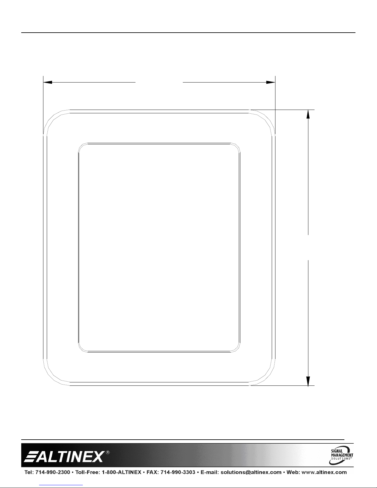
Step 1. Cut an opening into the table’s surface. Refer to the ALTINEX website at www.altinex.com for table cutout requirements.
Note: The table can be 2.50 in (64 mm) or less in thickness. Always confirm imensions before cutting to insure that specifications have not change .
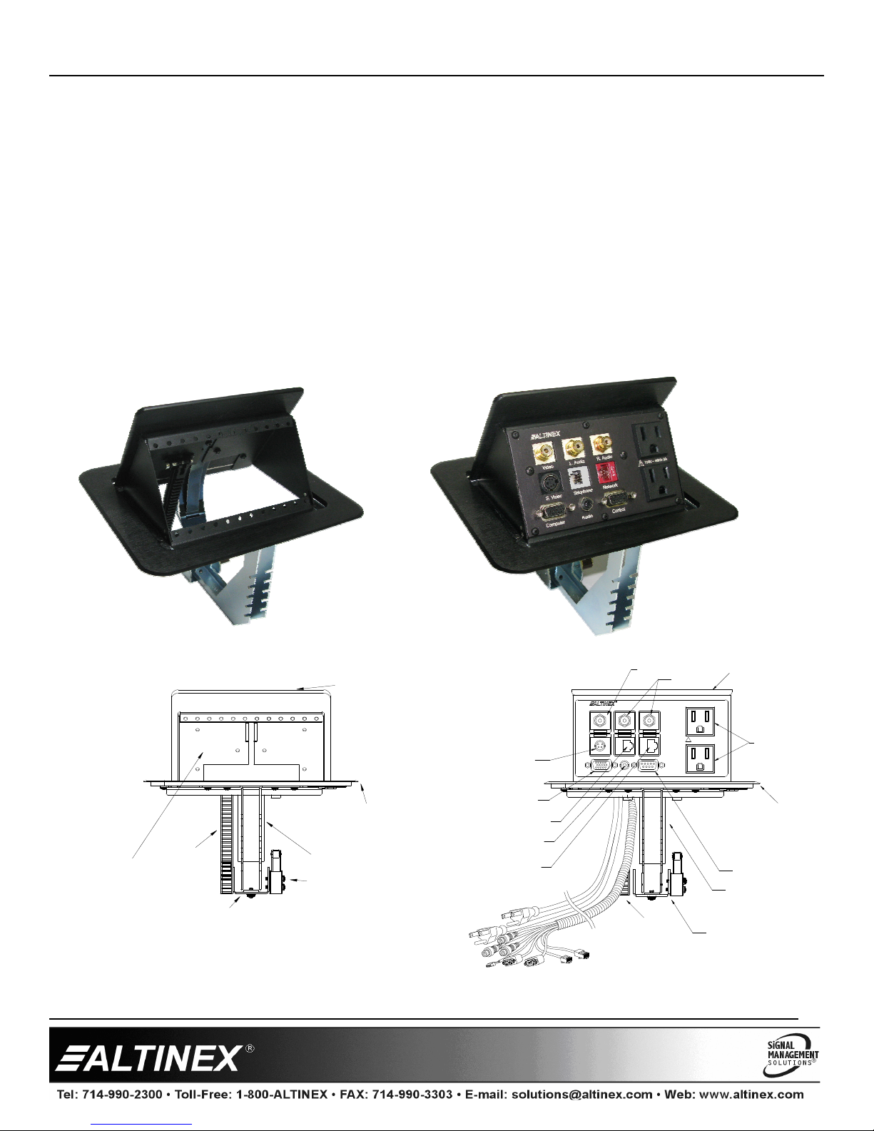
Step 2. Insert the TNP510/TNP512 into the table cutout.
Step 3. Place the support brackets un er the table an place them between the support mount grooves on the si e of the unit. Attach the brackets to the
groove at the esire height an secure them to the bottom of the table using the thumb screws provi e . See Diagram 5 for etails.
Step 4. To lower the unit, push on the top cover until it locks into place.
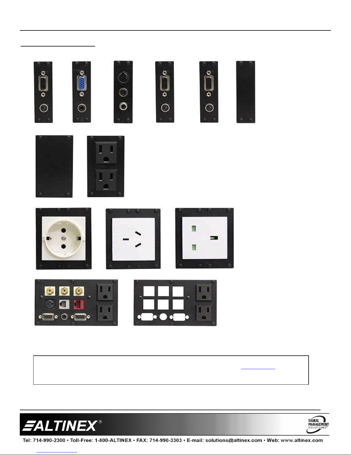
If Custom Plates are Installe
Step 5. Secure all cables to the un ersi e of the table using the cable clamps an screws inclu e with the TNP510/TNP512. Pass the power cor from the
bottom of the housing an attach it to the table separate from the signal cables.
Leave enough slack in the service loop to allow for easy opening an closing, but not too much as to cause excess rooping of the service loop.
Step
6. Connect the appropriate cables with the correct input connectors on the bottom of the unit.
Step 7. Once you have applie power an connecte the proper cables on the bottom of the unit you may raise the unit. To raise the unit into position, push
own on the front of the top cover; the latching mechanism will then release, allowing the pneumatic spring to raise it into position.
NOTE: It may be necessary to a just the service loop of the cables for optimal performance.
3. Limited Warranty/Return policies
Please see the ALTINEX website at www.altinex.com for etails on warranty an return policies.

Tilt ‘N Plug
Tilt ‘N PlugTilt ‘N Plug
Tilt ‘N Plug
User’s Guide
400-0521-001
2
4. Technical Specifications
Specifications are subject to change. See www.altinex.com for up-to- ate information.
Features/Description TNP510
Pass-Through
Sectional Plate Slots 6
Compatibility*
AC Power (U.S.) SP2102US, SP2107US
AC Power (International) DS901-
141, SP2201UK, SP2401AU,
SP2301CE, and SP2501SA
Audio, Video,
and Control
SP1500SC, SP3201AV,
SP3202AV,SP3203AV, SP3204AV,
SP3205AV, SP3206AV, SP3207AV,
SP3208AV, and SP3209AV
Blank Slot Covers SP1001BL, SP1002BL, SP1003BL,
SP1004BL, SP1005BL, and
SP1006BL
Customizable SP3212AV, SP3102EP, SP3103EP,
SP3104EP, SP3211NT, SP3408CR,
SP3402AD, and SP3403AD
Accessories Included
Miscellaneous Mounting hardware
Table 1A. TNP510 Description
Features/Description TNP512
Pass-Through
AC Power 10 ft (3 m)
110 VAC NEMA F-M (2 F to 1 M)
Audio/video 6 ft (2 m)
Computer Video 15-pin HD F-M (1)
Network RJ-45 F-M (1)
Modem RJ-11 F-M (1)
S-Video 4-pin Mini DIN F-M (1)
Composite Video Yellow RCA F-F (1)
Control DB-9 F-M (1)
Audio, Stereo 3.5 mm F-M (1)
Audio Left Channel Red RCA F-F (1)
Audio Right Channel Black RCA F-F (1)
Compatibility
Tilt ‘N Plugs TNP510
Accessories Included
Miscellaneous Mounting hardware
Table 1B. TNP512 Description
Mechanical TNP510/TNP512
Max. Table Thickness 2.5 in (64 mm)
Min. Table Thickness 0.5 in (13 mm)
Height, opened 7.5 in (191 mm)
Height (above table surface) 3.3 in (83 mm)
Height (below table surface) 4.2 in (107 mm)
Width 7.9 in (200 mm)
Depth 6.5 in (166 mm)
Finish Matte Black
T°Operating (T°Max) 10°C-35°C (40°C)
Humidity 90%non-condensing
Table 2. TNP510/TNP512 Mechanical
Electrical
(Single outlet panel) TNP510/TNP512
Pass-Through Signals All standard audio, video, network,
and modem signals are acceptable.
Pass-Through AC power
(Power Rating ) 600W maximum
Table 3. TNP510/TNP512 Electrical
*
Visit the ALTINEX website at
www.altinex.com
for a complete listing an escription of available plates, slot requirements, an connector options.

Tilt ‘N Plug
Tilt ‘N PlugTilt ‘N Plug
Tilt ‘N Plug
User’s Guide
400-0521-001
3
5. About Your Tilt ‘N Plug
• New leaf-spring replaces gas shock • Stan ar high-quality matte black finish
• Pop-up ampening for smooth operation • Custom finishes available (contact ALTINEX for options an pricing)
• Simple, rop-in installation • International power configurations available
The TNP510 an TNP512 are compact interconnect solutions esigne for mounting into tables, po iums, or other furniture as part of a presentation system.
Inputs are accesse by pushing own on the top cover allowing the units to "tilt" open. The inputs are hi en by pressing own on the top cover until the
latching mechanism engages. In the close positions, the top covers lie flush with the tabletop.
Signals are passe through the TNP510 an TNP512 sectional plates to the un ersi e of the table via cables with mating connectors on the opposite en . For
example, an RJ-45 F input connector is terminate in an RJ-45 M connector at the en of a 6 ft (2 m) cable. The TNP510 is empty, but provi es slots for 6
single-slot sectional plates that can be configure with various multime ia an power inputs. Many sectional plates are available for the TNP510 an or ere
separately. See our website for all options.
The TNP512 is a "package" that covers the basic nee s of many Tilt ‘N Plug users. This unit ships as a completely assemble pro uct ma e up of one TNP510 an
one SP3500SC Sectional Plate. The SP3500SC is engrave , rea y to go, an inclu es the following: 2 stan ar U.S. power receptacles, computer vi eo
(15-pin HD), COM Port/RS-232 (9-pin D), vi eo (RCA), S-Vi eo (4-pin mini DIN), au io (2-RCAs), computer au io (3.5 mm), mo em (RJ-11), an network
(RJ-45) input connectors. All connectors have 6 ft (2 m) cables attache that fee through to the bottom of the unit.
TILT UP LID
BEZEL
INTERFACE AREA
CUSTOMIZABLE
EMPTY/
SPRING LATCH
SUPPORT BRACKET
LEAF SPRINGS
DAMPENER
S-VIDEO
RJ-11 F
COMPUTER VIDEO
110V,5A
DB-9 F
RJ-45 F
RCA F (2)
RCA F
AC POWER
COMPOSITE VIDEO
AUDIO
110V 60Hz 5A
!
~
Audio
Computer Control
Video
S. Video
L. Audio
Telephone
R. Audio
Network
NETWORK CONTROL
TELEPHONE/MODEM
15-PIN HD F
4-PIN Mini DIN F
3.5 mm F
STEREO AUDIO
TILT UP LID
DAMPENER
LEAF SPRINGS
BEZEL
SUPPORT BRACKET
AND SPRING LATCH

Tilt ‘N Plug
Tilt ‘N PlugTilt ‘N Plug
Tilt ‘N Plug
User’s Guide
400-0521-001
4
6. Application Diagrams
Diagram 1: Typical Setup

Tilt ‘N Plug
Tilt ‘N PlugTilt ‘N Plug
Tilt ‘N Plug
User’s Guide
400-0521-001
5
Diagram 2: Front Dimensions
7.5"
[191 mm]
0.25" [6 mm]

Tilt ‘N Plug
Tilt ‘N PlugTilt ‘N Plug
Tilt ‘N Plug
User’s Guide
400-0521-001
6
Diagram 3: Side Dimensions
INTERFACE 3.3"
[83 mm]
4.2"
[107 mm]
5.9"
[150 mm]
OPERATOR

Tilt ‘N Plug
Tilt ‘N PlugTilt ‘N Plug
Tilt ‘N Plug
User’s Guide
400-0521-001
7
Diagram 4: Top Dimensions
6.5"
[166 mm]
7.9"
[200 mm]

Tilt ‘N Plug
Tilt ‘N PlugTilt ‘N Plug
Tilt ‘N Plug
User’s Guide
400-0521-001
8
Diagram 5: Mounting Sample
OPERATOR
BRACKETS (2)
SUPPORT
THUMBSCREWS (2)
TABLETOP
INTERFACE

Tilt ‘N Plug
Tilt ‘N PlugTilt ‘N Plug
Tilt ‘N Plug
User’s Guide
400-0521-001
9
Diagram 6: Popular Section Plates
Many ifferent plates can be installe o
n the TNP510 using up to 6 slots total. In a ition to stan ar plates, custom plates can be ma e
using blank plates available. For a complete listing an etaile escriptions, see the ALTINEX web site at www.altinex.com.
STANDARD PLA
TES
6 SLOTS
3 SLOT PLATES
2 SLOT PLATES
1 SLOT PLATES

Tilt ‘N Plug
Tilt ‘N PlugTilt ‘N Plug
Tilt ‘N Plug
User’s Guide
400-0521-001
10
7. Operation
7.1 Opening and Closing the TNP
The TNP510/TNP512 will open easily when the top is presse own an
then release .
When the TNP510/TNP512 is not in use, simply press the top own until it
is level with the surface of the table an then release. The unit will remain
hi en until nee e again.
7.2 Power/Signal Connections
Connect external evices to the appropriate connector on the
TNP510/TNP512. Remember, the evices plugge into the AC power
connectors shoul not raw more than 600W of power.
8. Troubleshooting Guide
The TNP510/TNP512 supplie was carefully teste an no problems were
etecte . However, we woul like to offer the following suggestions:
•Please make sure that the highest quality network cables are use .
•Make sure that no cable or power cor is amage or pinche . If
there has been amage, o not use the TNP510/TNP512. Please call
the ALTINEX Customer Service Department at (714) 990-2300 to
have the unit repaire .
•If the unit oes not rise into position correctly, check the service
loops for the signal an power cor s on the bottom of the unit.
This manual suits for next models
1
Table of contents
Other Altinex Control Unit manuals
Popular Control Unit manuals by other brands

S-Tech
S-Tech SV Technical manual

DMP Electronics
DMP Electronics 712-8 installation guide

Acromag
Acromag BusWorks 900PB Series user manual

Rochester Gauges
Rochester Gauges Magnetel Series installation instructions

Becker
Becker GS2 Assembly and operating instructions

Ericsson
Ericsson 9D902780G3 Maintenance manual