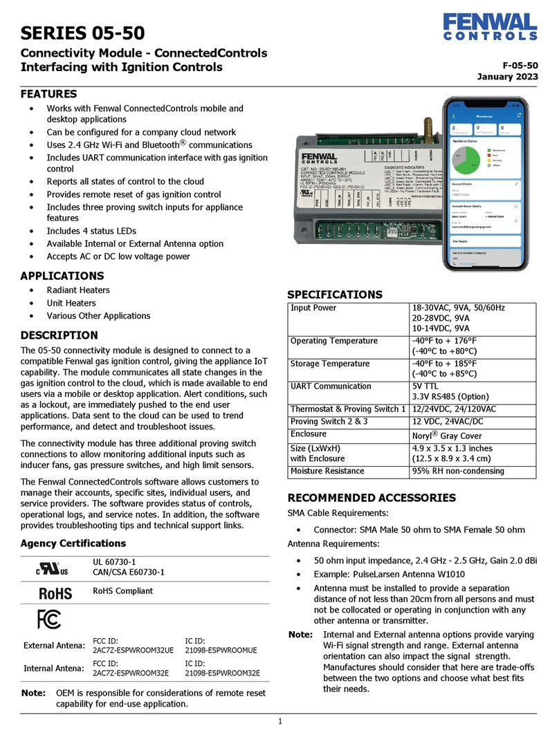
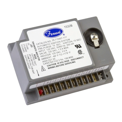
Fenwal Controls 35-9 Series User manual

F-35-2000
October 2018
1 of 12
Series 35-9X Modulating
Platform Ignition Module (PIM®)
OPERATION AND INSTALLATION INSTRUCTIONS
DESCRIPTION
The Fenwal Controls Platform Ignition Module (PIM®) integrates
the functions of Automatic Ignition Control with temperature
regulating and control functions. The PIM is designed for a range
of hydronic boilers including both staged systems and
modulating types. The PIM can be configured as a direct spark
ignition (DSI), intermittent pilot (IP) or Hot Surface Ignition
(HSI) to provide safe lighting and supervision of the burners in
an appliance. The PIM is also designed to connect to and receive
commands from the tekmar®1 Host Controller. When connected
to a Host Controller, the PIM offers expanded control
functionality including Domestic Hot Water, outdoor reset,
diagnostic messages, and other system capabilities.
APPLICATIONS
The PIM and Host Controller system is suited to a wide variety
of gas-fired hydronic heating systems including:
• High-efficiency Modulating Condensing Boilers
• Fan-assisted single and multi-staged Boilers
• Multiple Boiler Installations using intelligent sequencing
• Intermittent Pilot based Hydronic appliances
• Water Heaters
• Pool and Spa Heaters
AGENCY APPROVALS
SPECIFICATIONS
1.The tekmar BTCII Boiler Controller is fully compatible with
the Fenwal PIM and provides complete hydronic boiler
operation. For more information, contact tekmar controls at
(250) 545-7749.
2. EMC Emission testing to be verified after incorporation into
end use appliance.
CSA Design certified to ANSI Z21.20,
CAN/CSA C22.2 No. 199-M99 and ANSI
Z21.20-2014 CAN/CSA C22.2 No.
60730-2-5-14
CE Approved to EN 298-20122
WARNING
Installing or operating the product inconsistent
with these instructions or specifications could
cause serious property damage, injury or death.
Specification Value
Input Power Control: 18-30 VAC 50/60 Hz
(Class 2 Transformer)
Input Current Drain 400 mA @ 24 VAC with gas and
blower relays energized (Control
only)
Gas Valve Relays 5.0A max (continuous)
Combustion Blower 5.0 A max for standard (J2)
connection
15.0 A max for heavy-duty (K5
relay) terminals
Hot Surface Igniter 5.0 A max, 120/240 VAC
Pump Relays 5.0 A max (continuous)
Alarm Relay 2.0 A, 30 VDC or 30 VAC max
Operating Temperature -40°F to + 165°F (-40°C to +74°C)
Storage Temperature -40°F to + 185°F (-40°C to +85°C)
Sensor Temperature Range -22°F to + 260°F (-30°C to
+126°C)
Flame Sensitivity 0.7 μA minimum
Flame Failure Response or
Reignition Time
0.8 seconds maximum
Flame Detector Self-check Rate Once per second minimum
Flame Failure Lockout Time Varies by model
Types of Gas Natural, LP, or manufactured
Spark Rate Remote sense (50/60 Hz)
Local sense (25/30 Hz)
Size (LxWxH) 8.50 x 6.50 x 2.50 inches
(21.59 x 16.51 x 6.35 cm)
Ingress Protection Not rated, protection provided by
appliance in which it is installed.
Moisture Resistance Conformal coated to operate non-
condensing to 95% R.H.
Tries for Ignition One or three try versions available
Trial for Ignition Period 1 to 30 seconds, up to 300 seconds
(IP)
Pre-purge Timings 1 to 255 seconds
Inter-purge Timings 1 to 255 seconds

Effective: October 2018
2 of 12 F-35-2000
FEATURES
The PIM provides the following features:
• Integrated UL353 High Limit using Thermistor Sensor
• Configuration parameters selected through a unique
Identification Card
• Communicates via (RS485) with Host Controller
• Supports tN4 signals when using tekmar Host
Controller
• Measures Inlet, Outlet, Limit, and Vent temperatures
using NTC curve
J Thermistors, 10 KΩ(β3892) at 25°C (12 KΩ
Thermistors optional).
• Optional signals from DHW, System, and Outdoor Air
sensors to Host Controller for Outdoor Reset and DHW
functions.
• Supports external input (0-10 VDC or 4-20 mA) from an
Energy Management System
• Controls the Boiler, System, and DHW pumps
• Controls the gas ignition sequence in response to space
heating or DHW demand
• Pulsed Water Flow sensor input for optimizing DHW
performance
• Modulates the boiler firing rate using combustion
blower speed control, providing a PWM output or a 4-
20 mA signal.
• Closed-loop control of blower speed (RPM) through
tachometer signal monitoring
• Optional support for two-stage blowers by re-assigning
the DHW pump relay
• Low-voltage detection and safe shutdown below
18.0VAC supply input
• Hot Surface or Direct Spark Ignition (also allows for
external HV transformer)
• Intermittent Pilot Ignition (single stage only)
• Fail-safe Control for one or two stages of gas valves
• Optional Isolated (Dry) Contact Gas Valve operation
• Airflow, water flow and gas pressure switch monitoring
and diagnostics
• Optional automatic reset after ignition lockout (one
hour or as defined)
• Safe-Start and full-time Flame sensing
• Local (through the HSI or DSI element) or Remote
Flame sensing
• Configurable as needed to meet CSD-1 applications
• System and Control Diagnostics through use of on-
board or remote LED
• Communication of Diagnostic status to Host Controller
• Manual Reset for Ignition Lockout or Hi-Limit (on-board
or remote)
• Field Test/pump exercise capability
• Dry contact relay output for Alarm and Alert conditions
• Capability of two PIM operation to support up to 4 gas
valve stages using a master/member configuration
SENSORS
The PIM provides standard support for 10K ohm @ 77°F NTC
curve J Thermistor probes (β=3892). Special OEM models may
support other sensor types as outlined in the specific appliance
manuals. Optional 12k Ohm thermistor are available, consult
factory for details.
The Inlet, Outlet, Hi-Limit, and Vent (exhaust stack) sensors are
directly processed by the PIM. The optional System, Outdoor,
and DHW tank sensors are also connected to the PIM but passed
through to the tekmar Host Controller which is required to
provide those additional features.
ID CARD
The PIM determines its operating parameters by reading the
identification code of an external plug-in ID card.
Note: This ID card must be present for the PIM and
appliance to operate.
A total of up to 126 unique codes are supported. This card
selects the proper settings in the PIM's memory for appliance
models. These parameters include ignition timings and
operation; and system and OEM configuration settings.
Fenwal supplies the PIM with its internal ID card settings blank.
The first time a PIM is powered-up attached to an ID card, the
PIM stores the ID card setting in non-volatile memory. Once set,
the PIM only operates with the correct ID card installed that
matches the PIM’s internal ID settings. The PIM verifies the ID
card at power-up.
If a PIM needs to be re-configured for another ID card, such as
during service or replacement, its internal ID card settings must
be cleared. Contact the manufacturer for ID card reset process.
SEQUENCE OF OPERATION
Install the ID Card
The PIM must always have the proper ID card attached for
operation. The ID card is connected to J6 and determines the
correct configuration parameters and system timings for a
particular application. The ID card must always remain with the
appliance, even if the PIM needs to be replaced.
Potentiometer (Operator Setpoint)
The operating setpoint for PIM stand-alone mode is selected by
manually adjusting a potentiometer. The operating point for
outlet water temperature is settable from 110°F to 210°F.
Note: The operating setting used by the software limits the
maximum setpoint to the configured operator
safeguard (delta below the configured high limit
setpoint) to avoid nuisance trips regardless of the
potentiometer position.
WARNING
The ID card must remain with the appliance
for its entire service life. In the event of an ID
Card failure, replacement must be performed
by a qualified technician and must be
replaced with an ID card of the same number.
ID Cards cannot be interchanged between
appliances.

Effective: October 2018
F-35-2000 3 of 12
Configuration (DIP Switch Settings)
The PIM includes an 8-position DIP switch, located near the field
wiring terminals. Use this DIP switch to set field configurable
items when commissioning. The switch positions are listed in the
following table.
The default factory setting for each switch is the second
selection (off position).
Note: When a Host Controller is connected, higher level
functions for these options must be enabled first using
the DIP switch settings.
Start-Up
1. Upon application of 24 VAC power, the PIM resets with
all outputs in the off state.
2. The PIM performs a processor and memory self-test to
insure proper operation.
3. The PIM confirms the presence of a valid ID card which
matches the configuration previously stored in
memory. If the valid ID card is not present, the PIM
generates a diagnostic fault.
4. The PIM reads the DIP switch settings and configures
itself for the desired operation.
5. The Host Controller communications are scanned to
determine if a Host Controller device is present. If
found, system operation is controlled by the Host
Controller.
6. The non-volatile memory is checked for an active
lockout condition. A lockout indicates the previous
attempt to light was unsuccessful, or a hi-limit or other
system fault occurred. The PIM stays in lockout until a
manual reset is performed.
Standby/Call for Heat
1. The PIM continuously monitors the flame status to
verify no flame is present during Standby. If an
erroneous flame is detected, the PIM generates a flame
error fault.
2. The PIM verifies that the optional exhaust vent sensor
below the vent temperature limit before burner
operation can occur. If the vent temperature exceeds
the limit, the PIM performs a Post-purge and proceeds
to a Hard Lockout.
3. A Call for Heat is initiated by the presence of any one
or more of the four sources below:
– A heat demand (contact closure) on the TH field
wiring terminals
– A voltage greater than 0.5Vdc on the analog 0-
10Vdc EMS signal input
– A heat demand present on the DHW field wiring
terminals
– A heat demand from the Host Controller based on
the DHW sensor temperature
4. The PIM initializes the Trial for Ignition (TFI) counter to
the programmed number of trials and proceeds to
Pump Purge mode.
Pump Purging
Note: If a Host Controller is present, the PIM responds to
pump commands via the communication bus. When
the Host Controller determines the boiler needs to fire,
it sends a firing rate command to the PIM and
operation proceeds to Blower Pre-purge.
If the PIM is in stand-alone mode, the pumps operate as follows:
1. A call for space heating energizes the boiler and system
pump outputs.
2. The heat exchanger is purged providing flow past the
water pressure switch.
3. The pump pre-purge time begins after the water
pressure switch is proven.
4. If burner operation is required to meet the operating
setpoint, the PIM proceeds to Blower Pre-purge.
Blower Prepurge
1. The Gas Pressure switch(es) are verified closed.
2. The Airflow switch is verified open (shorted switch
detection).
3. The Combustion Blower is energized, and set to the
purge speed (if modulating).
4. The Airflow switch is verified to close within 60 seconds
to prove flow.
5. The configured ignition pre-purge delay takes place.
6. The voltage level of the 24 VAC supply input is
confirmed to be above 18.0 VAC.
7. If all checks are passed, the PIM proceeds to Ignition.
Table 1-1. DIP Switch Settings
Position Switch Description
1 Operator Differential (Manual/Auto Differential)
2 Analog Input Type (Direct Drive/Target
Temperature)
3PumpPostPurge(On/Off)
4 Pump Exercise Enable (On/Off)
5 EMS/Demands (PIM uses analog input only/
Host Controller or PIM
demands)
6 EMS Signal Type (4-20mA/0-10Vdc) * * 4-
20mA setting requires use of
external 500Ω, 1/2W resistor.
7 Freeze Protection (On/Off)
8 Commission Test (On/Off)

Effective: October 2018
4 of 12 F-35-2000
Ignition (DSI Models)
1. The PIM re-initializes the ignition counter to the
configured number of trials.
2. The High Limit sensor is confirmed to read below the
High Limit Set Point.
3. The blower light-off RPM speed is verified (modulating
type only).
4. The gas valve relay contacts are verified open (except
isolated valve models).
5. The Combustion Blower is set to the Ignition light-off
speed (if modulating).
6. The gas valve output is enabled for the trial for ignition
time to light the burner.
7. The HV spark output is enabled for the configured trial-
for-ignition time.
8. The flame sense is checked for successful lighting of
the burner. When a valid flame is detected during the
TFI period, sparking is terminated and the main gas
valve, operating pumps, and blower relay remain
energized and the PIM proceeds to the Heating mode.
9. If flame is not detected during the TFI period see
“Failure to Light - Lockout”.
Ignition (HSI Models)
1. The PIM re-initializes the ignition counter to the
configured number of trials.
2. The High Limit sensor is confirmed to read below the
High Limit Set Point.
3. The blower light-off RPM speed is verified (modulating
type only).
4. The gas valve relay contacts are verified open (except
isolated valve models).
5. The HSI Element proving current is verified to be above
the configured value. (proven hot-surface models only)
6. The configured heat-up delay takes place to allow the
hot surface element to reach ignition temperature.
7. The gas valve output is enabled for the trial-for-ignition
time to light the burner.
8. The hot surface element is de-energized during the last
second of the TFI period.
9. The flame sense is checked for successful lighting of
the burner. If a valid flame is detected during the TFI
period, the main gas valve, operating pumps, and
blower relay remain energized and the PIM proceeds to
the Heating mode.
10. If flame is not detected during the TFI period see
“Failure to Light - Lockout”.
Ignition (IP Models)
1. The PIM re-initializes the ignition counter to the
configured number of trials.
2. The High Limit sensor is confirmed to read below the
High Limit Set Point.
3. The blower light-off RPM speed is verified (modulating
type only).
4. The gas valve relay contacts are verified open (except
isolated valve models).
5. The Combustion Blower is set to the Ignition light-off
speed (if modulating).
6. The Pilot gas valve output is enabled for the trial for
ignition time.
7. The HV spark output is enabled for the configured trial-
for-ignition time.
8. The flame sense is checked for successful lighting of
the burner. When a valid Pilot flame is detected during
the TFI period, sparking is terminated and the main gas
valve is energized. The Pilot valve, operating pumps,
and blower relay remain energized and the PIM
proceeds to the Heating mode.
9. If flame is not detected during the TFI period see
“Failure to Light - Lockout”.
Heating
1. The flame status, airflow switch, LWCO switch, water
pressure switch and other safety switches are
continually monitored for proper state.
2. The High Limit sensor is confirmed to read below the
High Limit setpoint.
3. The boiler operating water temperature is monitored
against the target temperature to determine the proper
firing rate or staging level.
4. The PIM remains in heating mode until the staging
reaches 0% or the firing rate drops below the
configured minimum value for the burner.
5. A Blower Post-purge is completed and the control
proceeds to Standby mode.
Heat Demand Satisfied
1. The thermostat signal becomes inactive indicating the
call for heat is satisfied.
2. The gas valve(s) are immediately disabled.
3. A Blower and Pump Post-purge is completed before
returning to Standby mode.
FAILURE TO LIGHT - LOCKOUT
Single Trial Model
Should the burner fail to light or if flame is not detected during
the trial for ignition period, the control performs the following:
1. The control enters ignition lockout.
2. The gas valve(s) are de-energized immediately.
3. The LED indicates the fault code for ignition lockout.
Multi Trial Model
Should the burner fail to light or if flame is not detected during
the first trial for ignition period, the control performs the
following actions:
1. The gas valve(s) are de-energized.
2. The control then goes through an interpurge delay
before another ignition attempt.

Effective: October 2018
F-35-2000 5 of 12
3. The control attempts two additional ignition trials
before going into lockout and the gas valve relay(s) are
de-energized immediately.
4. The LED indicates the fault code for ignition lockout.
Lockout Reset
Volatile Reset Models
Recovery from lockout requires either pressing manual reset,
recycling the call for heat, or removing 24 volts for a period of 5
seconds. On models with automatic reset, if the call for heat is
still present after the configured reset time, the control will
automatically reset and attempt to start a new heating cycle.
Manual Reset Models
Recovery from lockout requires activation of the manual reset
switch or remote reset input.
High Limit Fault Reset
If the High Limit sensor detects a temperature above the High
Limit setpoint, the PIM will enter lockout. Recovery from a High
Limit fault requires activation of the manual reset switch or
remote reset input.
FLAME FAILURE RESPONSE
Recycle Mode
With "recycle after loss of flame", upon loss of flame, the gas
valve is de-energized within 0.8 seconds. After the flame recycle
delay, the control attempts to relight the burner. Multi-try
models allow three tries for ignition including inter-purges. If the
pilot burner relights, normal operation resumes. If the burner
does not relight, the control will go into lockout as described in
“Failure to Light - Lockout”.
Re-ignition Mode (Spark Models Only)
If the established flame signal is lost while the burner is
operating, the control responds within 0.8 seconds by energizing
the HV spark for the TFI period in an attempt to relight the
burner. If the flame is re-established, normal operation resumes.
If the burner does not light within the TFI, the gas valve is de-
energized immediately and on multi-try models a new TFI
sequence begins. Multi-try models will make 2 more attempts to
light the burner.
If the burner does not relight, the control will lockout as
previously described in “Failure to Light - Lockout”.
OEM FACTORY WIRING
Supplying Power
The PIM requires 24 VAC on Connector J11 to operate its
microprocessor circuits, the safety switch connections, and the
field demand inputs. An onboard fuse protects the 24 VAC
circuits and if configured for direct gas valve power, the 24 VAC
relay outputs to the gas valves.
Sensor Inputs
The PIM requires an outlet thermistor sensor for burner control
and a high-limit thermistor sensor for the integrated UL353 high-
limit function. These two thermistors must be independent but
co-located so they provide similar readings. The vent sensor and
inlet sensor are optional and if used should be enabled by the
parameter table settings.
Isolated Valve Contacts
If the optional isolated valve configuration is used, the valve
power and return must be separately supplied to J12 and the
valve outputs are not protected.
Combustion Blower Connections
The blower motor is connected to J13 operating off the power
supplied to L1, which can be 120VAC or 240VAC. If a modulating
blower is used, PWM or 4-20 mA signals are provided by
connection to J10. The blower motor tachometer signal is
required when configured for closed-loop fan speed control.
High-Current Blower Option
If provided, the relay contacts of K5 must be used to connect the
blower. The QC dry-contact terminals on top of the relay are
used for the blower output and supply voltage, which may be
120VAC or 240VAC. The maximum current rating is 15.0A.
Pump Outputs
The pump circuits are operated off the power supplied to L1 and
L1-S, which can be 120VAC or 240VAC. The boiler pump and
DHW pump are sourced from L1, while the supply pump (if
used) must be powered by L1-S.
Ignition Outputs
The PIM is capable of DSI, IP, or HSI ignition depending on
configuration. For spark ignition (DSI or IP) the electrode is
connected to the T3 ignition coil. For HSI the igniter element
connects to P1 and is driven off the L1 supply voltage.
If configured, an external spark ignition transformer can be used
by connecting it to P1. It is powered by L1 and the spark output
on T3 will be disabled.
SYSTEM CONNECTIONS (FIELD WIRING)
If used, the Host Controller must be connected to J4. The RJ-45
style 8-pin jack provides power, communications, and sensor
information to the Host Controller.
The PIM also acts as the central wiring point of a hydronic
system. Field wiring terminals on J1 and J2 allow connection of
optional DHW, outdoor, and system sensors, Host Controller,
EMS analog demand signal, LWCO, remote reset, water flow
switch, and the space thermostat and DHW demand inputs.

Effective: October 2018
6 of 12 F-35-2000
LED ERROR CODE LISTING
The following table lists the errors detected by the control and the associated LED indications
Error Mode LED Code Recommended Troubleshooting
Normal Operation Off
ID Card Fault Red LED Steady ON, Green
Power LED OFF
Check that the proper ID card is securely connected.
Perform a power and system reset.
Internal Control Failure Steady ON Perform a power and system reset.
If fault remains, replace the PIM.
Airflow Fault 1 flash Check Blower operation and airflow switch.
False Flame Error 2 flashes Check for proper gas valve closure.
Clean burner and electrodes.
Ignition Lockout Fault 3 flashes Check the gas supply.
Ignition Proving Current
Fault
4 flashes Check HSI element. Replace with a new element of the proper rating.
Low Voltage Fault 5 flashes Check the 24 VAC input voltage. The voltage must be above 18.0 VAC
Vent Temperature Fault 6 flashes Check for a blocked flue. Check the vent sensor and connections.
Hi-Limit Fault 7 flashes Check for proper water flow. Check hi-limit and outlet sensors.
Sensor Fault 8 flashes See Host Controller for fault identification. Check sensors and wiring.
Safety #1 Fault 9 flashes Check gas pressure. Verify proper safety switch operation.
Water Pressure Fault 10 flashes Check piping for leaks. Check pressure switch and connections.
Blower Speed Fault 11 flashes Verify tachometer signal and connection on J5.
LWCO Fault 12 flashes Check LWCO switch and connections. Check the water level.
Hi-Temperature Delta Fault 13 flashes Check pump operation. Confirm proper water flow across heat exchanger.
Ft-bus Communications
Fault
14 flashes Verify Host Controller is connected and operating. Check the cable between the
Host Controller and J1.
Safety #2 Fault 15 flashes Check gas pressure. Verify proper safety switch operation.
MOUNTING AND WIRING
The PIM enclosure is designed to facilitate mounting within a
control box by the appliance OEM.
The PIM is not position sensitive and can be mounted vertically
or horizontally. The case may be mounted on any surface using
four standard #8 sheet metal screws.
HIGH VOLTAGE AND REMOTE SENSE CABLE
REQUIREMENTS
The HV Ignition Cable must meet a voltage rating of 25 KV and
an insulation rating of 200 °C. Recommend length of 3ft (.9m)
or less. Consult factory for longer lengths.
Remote flame sense cable must meet a voltage rating of 250V
and an insulation rating of 200 °C. Recommended length of 10ft
(3m) or less. Consult Factory for longer lengths.
INDICATORS
The PIM has three LED indicators to display operational status
and to help diagnose system error conditions.
•Power: Green LED indicating the PIM module is
receiving 24 VAC power.
•Alarm/Test: Amber LED which indicates the PIM is in
Commission Test Mode or that a diagnostic alarm
(fault) is present.
•Diagnostic Code: Red LED that is normally off.
During a control or system fault condition, this LED
flashes the error codes. Refer to the following table for
additional details.
WARNING
The PIM must be mounted and located in a
manner which protects components from expo-
sure to water (dripping, condensate, spraying,
rain). Any control that has been exposed to
water must be replaced.
WARNING
All wiring must be done in accordance with both
local and national electrical code. Wiring must
be at least #18 AWG rated for 105°C or higher.
WARNING
The PIM uses voltages of shock hazard poten-
tial. Wiring and initial operation must be done by
qualified service technician.
WARNING
Operation outside specifications could result in
failure of the Fenwal product and other equip-
ment with injury to people and property.

Effective: October 2018
F-35-2000 7 of 12
WIRING DIAGRAMS
DSI Wiring Diagram
J4
J2 J1
SW2
For field settings,
see note
Limit
R91
Operator
Se t P oint
SW1
J15
D80
D23
D90
Remote
LED
D
RST
PWR
Reset
F1
T2
FS P2 GND
J5
J6
J7
J8
J9
J10
J11
J12
J13
J14
FC-
FC+
Remote Flame
Sense Rod
Host Controller Bus
DHW Sensor
System Sensor
Outdoor Senso
r
tN 4
+ EMS
- 0-10 V DC
Alarm
LWCO
Remote Reset
Flow Swit ch
DHW TH
The rmo st at
Host
Controller
FT -B us B
FT -B us A
PI M
Sla ve
V+
Boiler
Identity Card V in
GN
D
Hi gh Limit
Senso r
Outlet Sen sor
Air Flow
Sa fet y #2
Sa fet y #1
Inlet S ensor
Vent Sensor
4 to 20 MA
Fan Power (18 VDC )
Fan GND
Flow SE N GN D
Flow SEN P W (12 V DC)
PWM-Out
Flow Sens or
Tachometer
To J10 Pin 3
To J10 Pin 4
24 VA C
L1
L2
2 STG / MV
MV / PV
RTN
Hot
Dry
Contact
Blower
System
Pump
B oile r
Pump
DHW
Pump
L1 – S 120 VAC
120 VAC
120 VAC
11091
1
2
1
2
3
1
2
3
4
1
2
3
4
5
6
1
2
3
4
1
2
3
5
6
7
48
1
2
3
5
6
7
48
12
1
25
4
36
1
2
3
4
T3
Spark
Electrode
J3

Effective: October 2018
8 of 12 F-35-2000
HSI Wiring Diagram
J4
J2 J1
SW2
For field settings,
see note
Limit
R91
Op er ato r
Se t P oint
SW1
J15
D80
D23
D90
Remote
LED
D
RST
PWR
Reset
F1
T2
FS P2 GND P1
J5
J6
J7
J8
J9
J10
J11
J12
J13
J14
FC-
FC+
S2/FS
S1
Remote Flame
Sense Rod
Hot
Surface
Ignitor
DHW Sensor
Syst em Se nso r
Outdoor Senso r
tN 4
+ EMS
- 0-10 V DC
Alarm
LWCO
Remote Reset
Flow Swit ch
DHW TH
The rmo st at
FT -B us B
FT -B us A
PI M
Sla ve
V+
Boiler
Identity Card
V in
GN
D
Hi gh Limit
Senso r
Outlet Sen sor
Air Flow
Sa fet y #2
Sa fet y #1
Inlet S ensor
Vent Sensor
4 to 20 MA
Fan Power (18 VDC )
Fan GND
Flow SE N GN D
Flow SE N P W (1 2 V DC )
PWM-Out
Flow Sens or
Tachometer
To J10 Pin 3
To J10 Pin 4
24 VA C
L1
L2
2 STG / MV
MV / PV
RTN
Hot
Dry
Contact
Blower
System
Pump
B oile r
Pump
DHW
Pump
L1 – S
120 VAC
120 VAC
120 VAC
11091
1
2
1
2
3
1
2
3
4
1
2
3
4
5
6
1
2
3
4
1
2
3
5
6
7
48
1
2
3
5
6
7
48
12
1
25
4
36
1
2
3
4
J3
Host Controller Bus
Host
Controller

Effective: October 2018
F-35-2000 9 of 12
WIRING TABLES
OEM Factory Low-Voltage Wiring Connections (30 VAC Max)
Connector Pin Function Type and Rating
J5 1 Ft-bus B (PIM to PIM) Molex Micro-Fit, 20-30AWG, 2.0A
J5 2 Ft-bus A (PIM to PIM) Molex Micro-Fit, 20-30AWG, 2.0A
J6 1 ID Card Power (3.3Vdc) Molex Micro-Fit, 20-30AWG, 2.0A
J6 2 ID Card Signal Molex Micro-Fit, 20-30AWG, 2.0A
J6 3 ID Card Ground Molex Micro-Fit, 20-30AWG, 2.0A
J7 1 Hi-Limit Sensor Molex Micro-Fit, 10K Thermistor J curve
J7 2 Sensor Common Molex Micro-Fit, 10K Thermistor J curve
J7 3 Sensor Common Molex Micro-Fit, 10K Thermistor J curve
J7 4 Outlet Sensor Molex Micro-Fit, 10K Thermistor J curve
J8 1 Safety #1 switch Molex Micro-Fit, 20-30AWG, 2.0A
J8 2 Airflow switch Molex Micro-Fit, 20-30AWG, 2.0A
J8 3 Safety #1 return Molex Micro-Fit, 20-30AWG, 2.0A
J8 4 Airflow return Molex Micro-Fit, 20-30AWG, 2.0A
J8 5 Safety #2 switch Molex Micro-Fit, 20-30AWG, 2.0A
J8 6 Safety #2 return Molex Micro-Fit, 20-30AWG, 2.0A
J9 1 Inlet Sensor Molex Micro-Fit, 10K Thermistor J curve
J9 2 Vent Sensor Molex Micro-Fit, 10K Thermistor J curve
J9 3 Sensor Common Molex Micro-Fit, 10K Thermistor J curve
J9 4 Sensor Common Molex Micro-Fit, 10K Thermistor J curve
J10 1 4-20 mA Out (modulation %) Molex Micro-Fit, 20-30AWG, 2.0A
J10 2 PWM Out (modulation %) Molex Micro-Fit, 20-30AWG, 2.0A
J10 3 Flow Sensor Signal Molex Micro-Fit, 20-30AWG, 2.0A
J10 4 Tachometer Input Molex Micro-Fit, 20-30AWG, 2.0A
J10 5 Fan Power (18VDC) Molex Micro-Fit, 20-30AWG, 2.0A
J10 6 Fan Ground Molex Micro-Fit, 20-30AWG, 2.0A
J10 7 Flow Sensor Ground Molex Micro-Fit, 20-30AWG, 2.0A
J10 8 Flow Sensor Power (12VDC) Molex Micro-Fit, 20-30AWG, 2.0A
J11 1 24VAC Power (R) Molex Mini-Fit Jr. 30VAC, 8A
J11 2 24VAC Common Molex Mini-Fit Jr. 30VAC, 8A

Effective: October 2018
10 of 12 F-35-2000
OEM Factory Line-Voltage Wiring Connections
Connector Pin Function Type and Rating
J12 1 Valve common (isolated contact) Molex Mini-Fit Jr. 120/240VAC, 8A
J12 2 2nd stage Valve Molex Mini-Fit Jr. 120/240VAC, 5A
J12 3 Gas Valve Return Molex Mini-Fit Jr. 120/240VAC, 5A
J12 4 2nd Stage Valve Return Molex Mini-Fit Jr. 120/240VAC, 5A
J12 5 Gas Valve (MV/PV) Molex Mini-Fit Jr. 120/240VAC, 5A
J12 6 Valve Power (isolated contact) Molex Mini-Fit Jr. 120/240VAC, 8A
J13 1 Blower Output (L1) Molex Mini-Fit Jr. 120/240VAC, 5A
J13 2 Blower Return (L2) Molex Mini-Fit Jr. 120/240VAC, 5A
J13 3 Blower Ground Molex Mini-Fit Jr. 120/240VAC, 8A
J13 4 L1 supply input Molex Mini-Fit Jr. 120/240VAC, 8A
K5 Relay F1 and F2 terminals .250” QC terminals, 120/240VAC, 15A
J14 1 DHW Pump Molex Mini-Fit Jr. 120/240VAC, 5A
J14 2 Boiler Pump Molex Mini-Fit Jr. 120/240VAC, 5A
J14 3 L1s – System Pump Supply Molex Mini-Fit Jr. 120/240VAC, 8A
J14 4 System Pump Molex Mini-Fit Jr. 120/240VAC, 5A
J14 5 L1 Supply power Molex Mini-Fit Jr. 120/240VAC, 8A
J14 6 Not used Molex Mini-Fit Jr.
J14 7 L2 (neutral) Molex Mini-Fit Jr. 120/240VAC, 8A
J14 8 Pumps GND Molex Mini-Fit Jr. 120/240VAC, 8A
HV Spark Output (T3 coil) .250” QC terminal, 25kV
GND Burner Ground .250” QC terminal
S1 Hot Surface Element .250” QC terminal, 5.0A Max
S1/FS Hot Surface Element .250” QC terminal, 5.0A Max
FS Flame Sense Rod .250” QC terminal
P2 FC+ Flame Current Measurement .156” pin header
P2 FC- Flame Current Measurement .156” pin header

Effective: October 2018
F-35-2000 11 of 12
Low-Voltage Field Wiring Connections (30 VAC Max)
Connector Pin Function Type and Rating
J4 1 DHW sensor (to Host Controller) RJ45
J4 2 System sensor (to Host Controller) RJ45
J4 3 Outdoor sensor (to Host Controller) RJ45
J4 4 Host Controller RJ45
J4 5 Host Controller RJ45
J4 6 Host Controller RJ45
J4 7 24VAC Common RJ45
J4 8 24VAC Power (to Host Controller) RJ45
J3 1 Host Controller Bus 22AWG twisted pair
J3 2 Host Controller Bus 22AWG twisted pair
J2 1 DHW Sensor 10K Thermistor J curve
J2 2 DHW Sensor Common 10K Thermistor J curve
J2 3 System Supply Sensor 10K Thermistor J curve
J2 4 System Sensor Common 10K Thermistor J curve
J2 5 Outdoor Sensor 10K Thermistor J curve
J2 6 Outdoor Sensor Common 10K Thermistor J curve
J2 7 tN4 Communications Network Signal
J2 8 0-10Vdc Analog EMS Input 0-10 VDC or 4-20mA
J2 9 Common GND
J1 1 Alarm Contacts 0-30VAC, 2.0A Max Dry contact
J1 2 Alarm Contacts 0-30VAC, 2.0A Max Dry contact
J1 3 Low Water Switch (LWCO) 0-30VAC, 2.0A Max
J1 4 24VAC out (R) 18-30VAC, 2.0A Max
J1 5 Remote Reset 0-30VAC, 2.0A Max
J1 6 Water Pressure Switch 0-30VAC, 2.0A Max
J1 7 24VAC out (R) 18-30VAC, 2.0A Max
J1 8 DHW Call (DHW) 0-30VAC, 2.0A Max
J1 9 Heat Call (TH) 0-30VAC, 2.0A Max
J1 10 24VAC out (R) 18-30VAC, 2.0A Max

Fenwal Controls, Kidde-Fenwal Inc.
400 Main Street
Ashland, MA 01721
Tel: 800-FENWAL-1
Fax: 508-881-7619
www.fenwal.com
tekmar is a registered trademark of tekmar Control Systems Ltd. and tekmar Control Systems, Inc.
PIM is a registered trademark of Kidde-Fenwal Inc. All other trademarks are the property of their respective owners.
This literature is provided for informational purposes only. KIDDE-FENWAL, INC. believes this data to be accurate, but it is published and presented without any guarantee
or warranty whatsoever. KIDDE-FENWAL, INC. assumes no responsibility for the product's suitability for a particular application. The product must be properly applied to
work correctly. If you need more information on this product, or if you have a particular problem or question, contact KIDDE-FENWAL, INC., Ashland, MA 01721 USA.
Telephone: (508) 881-2000.
F-35-2000 Rev AB
©2018 Kidde-Fenwal, Inc.
12 of 12
PIM PART NUMBER
The following image explains the meaning of the various digits in the part number. Use this information to order the correct board.
35 – 9 X X X X X X X X–
IGNITION TYPE
1 = Direct Spark
2 = Direct Spark with External Relay
6 = Hot Surface Ignition
7 = Proven Hot Surface Ignition
VALVE/FAN CONFIGURATION
0 = Modulating (1-stage)
1 = One Stage
2 = Two Stage
3 = Intermittent Pilot (PV/MV)
4 = One Stage with Auxiliary
5 = Isolated M odulating (1-stage)
6 = Isolated One Stage
7 = Isolated Two Stage
RESERVED
0 = Standard Model
0-9 = Special Feature Assignment
TERMINAL CONFIGURATION
0 = Standard
1 = Pluggable Field Terminal Blocks
BLOWER RELAY
0 = Standard (5A)
1 = High-Current (15A)
FL AM E SENSE METHOD
0 = Local Sense
1 = Remote Sense
3 = Dual (Local and Remote)
RESERVED
0 = Standard Model
0-9 = Special Feature Assignment
MODEL CONFIGURATION
0 = North American (C22.2-199) Standard Model
2 = CE (EN298 & 60730) Standard Model
3 = CE (EN298 & 60730) OEM Special Feature Model
5 = North American (60730) Standard Model
6 = North American (60730) OEM Special Feature Model
9 =North American (C22.2-199) OEM Special Feature Model
Description
EXPORT INFORMATION (USA)
Jurisdiction: EAR
Classification: EAR99
This document contains technical data subject to the EAR.

Fenwal Controls
400 Main Street
Ashland, MA 01721
Tel. (508) 881-2000
© Kidde-Fenwal Inc. 06-237657-001 Rev AC
EU DECLARATION OF CONFORMITY
We
Company Name: Kidde-Fenwal Inc.
Postal Address: 400 Main Street
City and Post Code: Ashland, MA 01721
Tel: 508-881-2000
Declare that the DoC is issued under sole responsibility and belongs to the following product:
Apparatus Model(s) Series 35-40, 35-53, 35-60, 35-61, 35-63, 35-608, 35-65, 35-66, 35-9X
Type: Fitting
Batch Number Date code and Revision Level Assigned per production lot, (YYWW RR)
Object of the Declaration:
Series 35-40, 12/24Vdc Direct Spark Automatic Gas Ignition Controllers
Series 35-53, 12Vdc Direct Spark Automatic Gas Ignition Controllers
Series 35-60, 35-61, 35-63, 35-608 24Vac Direct Spark Automatic Gas Ignition
Series 35-65 & 35-66 24Vac Hot Surface Automatic Gas Ignition Controllers
Series 35-9X Platform Ignition Module
SERIES 35-40 SERIES 35-53 SERIES 35-60/61/63/608 SERIES 35-65/66
SERIES 35-9X
The object of the declaration described above is in conformity within the relevant union
harmonization legislation:
Gas Appliance Regulation: (EU) 2016/426 Low Voltage Directive: 2014/35/EC
EMC Directive: 2014/30/EC Rohs 2011/65/EU
The following harmonized standards and technical specifications have been applied:
EN298:2012: Automatic Burner Control systems for Burners and appliances burning gaseous or liquid fuels.
EN13611:2007_A2:2011: Safety and control devices for Gas Burners and Gas burning appliances – General Requirements.
Name of Notified Body & Number: BSI Group, 0086, EU Type Examination Certification
Notified Body Certificate No.: Series 35-40: CE682407
Series 35-53 CE682404
Series 35-60/61/63/608 CE682405
Series 35-65/66 CE682406
Series 35-9x CE690652
Surveillance Audit Notified Body: BSI Group
For copies of the Installation Instructions and the EU DoC, got to www.fenwalcontrols.com, - Document Library - Data sheets.
Paul Finn
Kidde-Fenwal, Inc. Ashland, MA USA 01 Oct 2018 Paul Finn, Certification Engineer
Place of Issue: Date of Issue Name
Table of contents
Other Fenwal Controls Control Unit manuals
