Bell RT-75 User manual

PrtoroFAcr* FolJ"t
SPEED CI{ANGE
ON-OFF CONTROL RfdV IND-
TONT CONTROL
gRECORD BUTTON
FAST FORWARD"' RUN'STOP
CONTROL
VOLUMT CONTROL
MODEL R.T-75
3.SPEED
TAPE
RECORDE R
AND PLAY BACK UNIT
Manufactured by:
BELL SOUND SYSTEMS, INC.
A Subsidiary of Thompson Products, lnc.
555 Marion Road
Columbus, 0hio
fhis moleriol compiled ond published by
HOWARD W. SAltS & CO., lNC., INDIANAPOLIS, INDIANA
Copyright 1956 . All RighB Resoryod
DATE 9-50
'NODEL R,T.75
u.l
t\
I
l-
c,
J
EI
a
o
=
=
o
E'
FI
F
v
-l
I
\
Ut
$ET 329 t0tDtR 4

FAST FWD.
ADJ. SCRNru
Figure I
GENERAL INFORMATION
The Bell Model RT-?5 is a three speed, dual
track tape recorder.
A single control knob turns power to the motor
and amplifier "On" and "Off" and selects the desired
speed (1 7/ 8, 3 3/ 4, or ? y 2 inches per second).
The dual track feature allows more recording
time on each reel and with light weight tape, as much
as eight hours total or four hours each side, may be
had on a ?t'reel at slowest speed.
"Fast Rewind"; these same buttons act as "Volume"
and "Tone" controls.
Two output jacks permit use of an external
speaker or high fidelity amplilier system. Aterminal
stripinsidethe amplifier isavailable for 500 ohm out-
put, at 30dbm level.
A removable cover plate on the bottom of the
cabinet allows easy access to tubes, motor, fan, hum
adjustment, and 500 ohm output terminal.
Built in interlocks prevent the operator from
placing the machine in more than one mode at a time.
This prevents tape brealage, spillage, or accidental
erasure.
Page 2
SPECIFICATIONS
Size: 16 3/ 8" x 15" x 9 V 8" less hardware.
Weight: 35 lb. approx.
Power Required: 110-120 volts 60 cycle A. C. only -
td-6wffi-
Overall Frequency Response: 30 to 10,000 cycles at
?-luT. trs:-
fier - TV.
Push buttons provide for "Fast Forward" and
Inputs (three): 2 microphones, I radio-phono-ampli-
Outputs (two): External Speaker, actual impedance
3. 2 ohms - use any speaker 4 to 16 ohmsl External
Amplilier, high impedance.
Power Output: 3 watts.
Speeds (three): Play or Record. 7 I/2, 3 3/ 4, or
i-?/8-Effis per second.
Fast Forward: 1200 ft. in 90 seconds.
Fast Rewind: 1200 ft. in 70 seconds.
Wow and Flutter: Less tian .25% at ? V 2 I. P. S.
Speaker: 6rr x 9r' heavy duty oval,

Type of Erase and Bias: Iligh Frequency (A. C. ) 60KC.
Tube Complement: 1-12AY7 or ECC-83, l-12AX7,
1-6C4, l-6V6cT, 1-6X5cT.
Controls: 1. Speed Change, On-Off Control.
2. Run-Stop Control.
3. Record Push.Button.
4. Tone and push button rewind.
5. Volume and push button fast forward.
OPERATI NG INSTRUCTIONS
Preparing The Bell For Recording-
1. Place the recorder on a flat surface and
remove the eover. Make certain that the "Run-Stop"
control is in the "Stop" position and that the "Speed"
control is in the "Off" position.
2. Insert the A. C. power cord plug into a con-
venient 110-120 volt, 60 cycle A. C. outlet.
Threading The Tape-
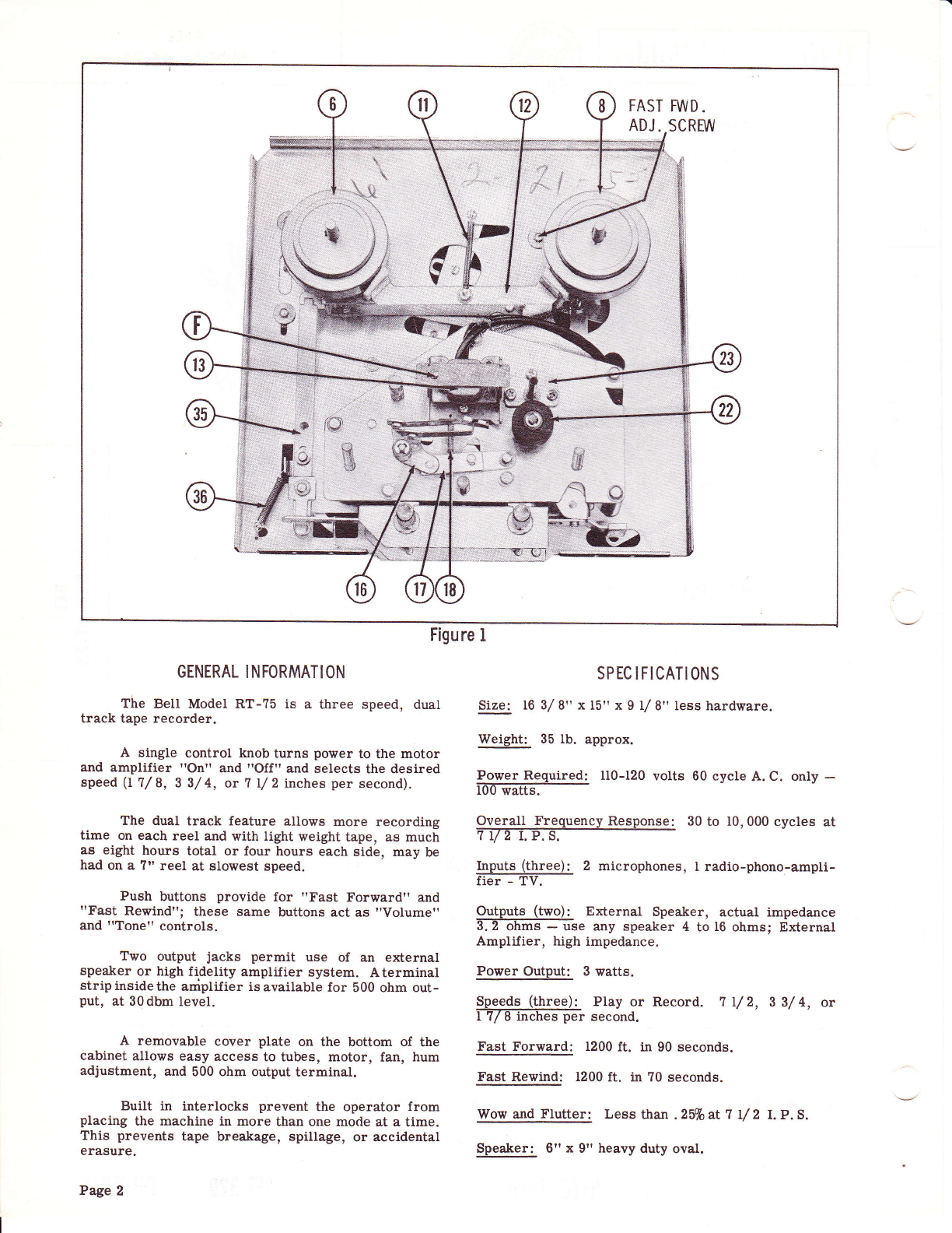
1. Place a reel of rtA, wind tape on the supply
reelsupport (6) and an empty reel of the same size on
the taleup reel support (8).
2. Unwindabout two feet of tape. Hold a section
oftapestraightwith both hands and insert the tape into
the tape slot. Insert the free end of the tape into one
of the radialslots in the hub of the empty reel. Rotate
reel counter clockwise three of four turns to secure
and take up all slack between reels.
To Record From Microphone-
1. Turn recorder on by placing speed control
knob (1) in t}te speed position desired. Allow approxi-
mately 30 seconds for the unit to warm up. Insert the
microphone plug into the Mic. I input jack. Use Mic.
2 input jack only when using two microphones or when
mixing with Radio, Phono., or TV programs. If
microphone is set on a hard surface, place sponge
rubber or several thicknesses of cloth underneath it
to absorb any vibrations, Set record level before
recording by depressing the red record button and
observing the flash of the neon record level indicator.
While sound source is striking microphone, carefully
adjustthe volume control so thatthe levellamp flashes
on peak passages.
NOTE: Correct recording volume is very important.
If the neon level lamp flashes all the time,
the recordingwill be overloaded and distorted
on playback. If level lamp does not flash at
all, playback will be weak and contain high
background noise.
2. After level adjustment has been set, turn the
run-stop control (2) to "Run". Thetape is now moving
and any sound entering the microphone will be re-
corded on the tape. When recording is finished, turn
control (2) to "Stop".
To Record From Radio. Phono. Or TV-
Recordings can be made from a radio or tele-
vision reeeiver by placing the microphone near the
loudspeaker, howeverthis type of recording is usually
not satisfactory beeause of background noises picked
up by the microphone and lack of good quality. A
better recording can be made by connecting the "Radio"
inputof the recorderto the radio or TV voice coil ter-
minals, In the case of an AM-FM Tuner, connect to
the tuner output.
Dual Track Operation-
NOTE: Recordings are made on half the width of the
tape at one time. Since it is impossible to edit
and splice one "track" without affecting the
other, recordings which are to be edited should
be limited to one track.
l. After a reel of tape has been recorded, a
second track may be recorded on the same reel (without
rewinding) by removing the full reel from the right hand
spindle, turning it over, t}ten placing on the left hand
spindle. Placethe emptyreel onthe right hand spindle.
2. Rethreadthe tape andproceedwiththe record-
ing as previously described.
3. Afterthesecondtrack has been recorded, the
first track is ready to be played without rewinding, by
changing reels as described in Step #1 above.
To Rewind-
After a recording is made, tape maybe rewound
by pushing "Rewindrrknob downpositively. Itwill lock
in position Fo it is unnecessary to hold down. When
desired portion of tape is rewound, push down and
release I'Fast Forwardrr knob. This will stop ttre tape.
When rewinding a complete or large portion of a reel,
it is better to take tape out of slot and run straight
across from reel to reel. Thissaves wearonthe head
and is somewhat faster since it eliminates the drag
set up by the tape running through the head slot.
To Play A Recording-
l. To play back recordings, place reels on reel
supports and tlread as previously described. Turn
the speed control pointer (1) to the correct speed; this
alsosupplies power tothe motor and amplifier. Plaee
the run- stop pointer (2) in the "Run" position and adjust
the "Volume" and "Tone" controls for desired listening
level. If speed of tape is unknown, the speed control
pointer (l) can beturned afterthe unitis playing. After
the recordings have been played, return the run-stop
pointer (2) to the "Stop" position. This releases the
pressure roller (22) from the capstan and stops t}e
tape.
2. After the first track has been played, the
second track may be played, without rewinding, by turn-
ing the reels over and placing them on opposite reel
platforms. This may be done at any time during
playback.
NOTE: When recordings are played back thru the
built-in speaker, remove anyphone plug which
may be inserted in either the External Speaker
or High-Z output jacks. These jacks, when
used, disconnect the built-in speaker.
Fast Forward-
In playback, it is sometimes desirable to skip
portions of tape to a particular spot. To do this, push
down and hold "Fast Forward" knob until tape arrives
i
\=/ =o
Hr
FrlF
nF
{
I
\
lrr
Page 3

Figure 2
at desired spot. To stop tape, release the "Fast
Forward" knob. To prevent unnecessary head wear,
tape should be taken out of head slot when large por-
tions of a reel are to be skipped.
D I SASSEMBLY I NSTRUCTIONS
Top-Deck Plate-
To service parts located directly under the top-
deck plate (5) it is not necessary to remove the unit
from the case. Remove top-deck plate as follows:
Remove four screws (one in each corner of the
turned down flange) and use a #10 spline wrench to
remove the two pointer knobs. Lift top-deck plate
straight up.
To Remove Recorder From Cabinet-
To remove recorder from cabinet, first remove
the top-deck plate (5). Next, removethe three screws
fromtherearof the cabinet located just above the vent
grille. Remove four screws from the bottom of the
case and liJt recorder straight up. Remove speaker
leads before lifting recorder completely out of case.
To Remove Amplifier From Transport Mechanism-
For some mechanical adjustments on the bottom
of the tape transport mechanism, it will be necessary
to {irst remove the amplifier. Remove as follows:
Remove three sheet metal (hex. head) screws
from each side plate. Remove four hex. head screws
fromthe jackand lamp brackets, 2 each side. Remove
Page 4
head plug and motor plug from their sockets. Loosen
the three Phillips head screws in the right hand side
plate so that the amplifier and power cord will miss
flanges as the mechanical unit is lifted straight up.
Tighten the three Phillips head screws in the right
hand side plate and place the mechanical unit on a flat
surface.
ADJUSTMENTS
When the amplifier is removed from the mechani-
cal unit, tape may be placed on the unit and driven in
anymodelbyusinganAC power cord with a socket that
willfit the motor plug. On units with serial #14, 000 to
15,200 use a Bell part #B-20209P19 socket. On units
above serial #15,200, use a Bell part #B-20209P29
socket.
Rewind Belt Adjustment-
Leave 12 to 15 turns of tape on the take-up reel
(right hand) and push rewind button all the way down.
Tape should start in motion. Il the recorder meets
this test, shutoff the motor with speed control pointer
(1). Place run-stop pointer (2) in the run position.
Now start the motor by placing speed control pointer
(l) in the 7 I/2I.P.S. position. The motor shoutd
starttapeunderload, not stall. If motor stalls, re',vind
belt (6?) is too tight. If machine fails to rewind last
few turns of tape, rewind belt (6?) is too loose. Make
adjustment as follows, if necessary.
Remove the reels and loosen the two screws (l/ 2
turn) which mount the rewind idter pulley assembly
(66). To loosen belt, reach under bottom plate and
slide the rewind idler pulley assembly (66) toward the

Figure 3
front and to the left. To tighten belt, move idler as-
sembly (66) toward the rear and to the left. Move the
idlerassemblyaboutl/ 32,' at a time, theninstall reels
and re-make tests.
Fast Forward Adjustment-
Leave 12 to l5 turns of tape on the left hand (supply)
reeland push fast forward button all the way down and
hold. Tape should start to wind in forward direction.
. Next, holdright hand (take up) reel from turning
(do not press down). Observe the take-up belt (?3), it
must be turning and clutch plate (9) must be slipping
against the take-up reel support (8). when the fast
forward button is held down. If take-up belt (?B) does
not turn, it is too loose. Mal<e adjustment as follows,
if necessary:
Loosen the fast forward adjustment screw (see
Figure 2) about I/ 2 twn. Totighten belt, reach under
bottomplate and slide the fast forward and play pulley
assembly (71) away from the take-up reel support (8).
Move very little at a time as this adjustment is very
critical. After adjustment is made, tighten screw.
Check adjustment as follows:
1. Do not load tape on recorder.
2. Place run-stop pointer (2) in the "Stop" po-
sition.
3. Place speed control pointer (l) in one of the
three speed positions.
4. Graspthemajorbrake assembly(12) and pivot
it toward the front of the recorder. The take-up reel
support (8) mustnotturnwhen the bra-kes are released.
lf reel support (8) turns, belt (?3) is too tight.
Brake Adjustments - (Refer To Figure 5)-
Check brake operation as follows before making
adjustments:
l. Placeafull ?" reeloftape on the take-up reel
support (8) and an empty reel on the supply reel support
(6). Do not place tape in head slot but run straight
across from reel to reel. Place recorder in "Rewind"
position andwhen tape is up tofastest speed, stop tape
by depressing the "Fast Forward" button. Release
immediately. Tape must not spill or throw loops.
2. Place nearly a full reel on the supply reel
support (6) and thread tape straight across from reel
to reel (not through head slot). Placerun-stopcontrol
in the I'Run" position (this eliminates holdingfast for-
ward button down). When tape has reached fastest
speed, place run-stop control in the ilStopt'position.
Tape must not spill or throw loops.
If brakes require adjustment, do so as follows:
1. (Forunitswith serial #14,000 to 15,200 only).
Checkthetwo dimensions as shown in Figure b. Mea-
sure from inside bottom plate flange to edge of brale
pivotbracket. This should measure 2l/4,,. Toadjust
for both dimensions, loosen the two screws (A) and
re-position the brake pivot bracket.
2. (This adjustment is for allunits). Check space
between brake lever cam and brake lever (35). There
should be some play, about I/ 64". Also check to see
thatthebrakelevercam is approximately in the center
of the control arm slide (45).
Test brake release in Fast Forward, Rewind, and
Run. Brakes must release in all three positions.
=
o
Hr
Fll| F
VF
I
\
gt
Page 5

Figure 4
To change clearance betweenbrakelever (35) and
brake lever cam, loosen scretvs (B) holding brake lever
bracket, Move bracket forward or backward. to obtain
t}:.e I/ 64" spacing. Use this same adjustment to center
cam in control arm slide (45). Move bracket to right
or left to obtain correct spacing.
NOTE: (Forunits with serial #14, 000 to 15, 200 only).
If brakes release more in one direction than
another, that is more in fast forward than in
rewind or visa versa, this can be equalized
bysliding the brake lever bracket to the rlght
or left after loosening screws (B).
Speed Slide Cam And Damper Adjustment-
;ure r-)=
l. (For units with serial #14,000 to 15,200 and
for units with serial numbers beginning with 25,000,
35,000 and 45,000). Speed cams (40), (41), and (42)
must clear the control pins (point "C" Figure 2) by
approximately V 16" when that particular slide is en-
gaged. Positionof motor on motor mounting plate and
positionof motor mounting plate on spacers will effect
this. See paragraph on motor mounting.
The control pins (point "C" Figure 2) must be
in the center of the speed cam notch(40), (41), or (42),
when that particular slide is engaged. To adjust,
loosen set screw and turn cam. Spacing betrveen the
phenolic slides should be such that they are parallel
Page 6
to top and bottom plates. If a phenolic \ryasher is used
above cam, spacebetween cam and slide is about .008
inch, if no rfasher, about .025 inches. Slide cam (40),
(41), and (42) up or down to adjust. Adjust bottom
cam (42) first.
2. (For units with serial #14, 000tol5,200only).
The phenolic slides must clear the sides of speed slide
bracket (44) when that particular slide is engaged.
Speed slide bracket (44) should be located as near the
motor pulley and pressure roller (22) as the mounting
slots will permit. This will allow ful1 use of the slide
springs,
3, (This applies to all units). The speed slide
dampers (point "D" Figure 2) must press down firmly
on the phenolic slides to hold idler wheels in position
when engaged. However, this damper spring must not
interferewiththesmooth operation of the slide against
its spring tension. Adjust damper springs carefully
with mounting screws on side of speed slide bracket
(44).
Capstan Actuating Cam (30) Adjustment-
The capstan actuating cam (30) must have some
end play between top plate (2a) and the capstan pres-
sure arm (27). Also, there must be some play between
cam (30) and flywheel (29). To adjust, turn run-stop
control (2) to "Run". Loosen set screw in cam hub

Figure 5
-
o
Ht
Flt F
VF
I
\
Ctr
and slide cam (30) up or down. While making this
adjustment, push wrench toward rear (turning cam)
until pressure roller (22) is pushed away from the
capstanshaft. Now, backup(pull wrench toward front)
and alter pressure roller (22) meets capstan shaft,
move still further to provide some clearance. Check
height of cam (30) again and tighten set screw.
Record Safety Release Cam (31) Adjustment-
(For units with serial #14,000 to 15,200 and for
units with serial number beginning with 25,000 and
35,000). Adjust record safety release cam (31) with
the run-stop control (2) in the ,'Run" position. With
the point of the cam to the left, adjust cam so that the
front diagonal slope of t}le pointer is parallel to the
front of the bottom plate. Adjustheight so that it con-
tacts record safety release (point "E" Figure 2) ap-
proximately in the center.
With control (2) still in the "Run" position, adjust
the safety release (point "E" Figure 2) so that it points
to the center of the run-stop control shaft. Adjust by
sliding to right or left in the slotted hole. Keep at
right angles to the bottom plate. Tighten screw.
When properly adjusted, the red record button
should return to its "up" position when run-stop control
(2) is placed in the "Stop" position.
Motor Mounting And Spacing Adjustment-
(For units with serial #14,000 to 15,200). The
motor mounting plate (59) is mounted on rubber shock
mounts and if replaced or removed for any reason the
spacing between flywheel (29) andthe largest diameter
of themotorpulley should be checked. This dimension
shouldbe .410 to .420 inches and can be accomplished
bymoving the motor plate on its spacers (3 hex. nuts)
or by moving the motor on the plate (2 hex. nuts).
At the same time above dirnension is checked,
cheek the control pin adjustment as deseribed under
"Speed Slide Cam And Damper Adjustment". The motor
must be positioned to meet both of these dimensions
for good operation.
Volume And Tone Control Alignment-
If the volume or tone controls bind when rotated
ineitherdirection, remedyas follows: Remove driver
linkage from both controls. Loosen hex. nut on both
controls. Use another 3/ I - 32 nut and lock down tight
on top of first nut, both controls. Thiswill allow .010
to . 012 play inthe control shalts andwill prevent binding"
Hum Adjustment-
The hum adjustment is located on right center of
recorder, looking at vent opening with recorder resting
Page ?

A PHOTOFACT "€XPLODED" VIE\?
O Ho*od V Srms a Co., lnc. 1956
Figure 6A. Exploded View 0f Parts Above Baseplate.
Page I

A PHOTOFACT "EXPLODED" VI€W
o How.d v. s.h. & co., tic. 1955
Figure 68. Exploded View 0f parts Below Baseplate.
=
o
H*
FlnF
70F
I
\
{,|
Page 9

on back of case. To adjust, position recorder away
from all strongelectricalfields, such as transformers
in amplifiers, motors, etc. Adjustwith "Volume" and
"Tone" controls at maximum. Adjust for minimum
hum. Try line cord plug both ways.
Ilead And Pressure Pad Adjustments-
To prope rly check head alignment it is neces sary
to have a reel of pre-recorded alignment tape of I mil
wave length. Play alignment tape back through recorder
withan A. C. vacuum tube voltmeter connected across
the speaker or 3.2 ohm load. Turn "Volume" and
"Tone" controls full on. Output voltage should be 1.3
volts or higher. (
CAUTION: Be sure recorder is in "Play" position to
prevent erasure of alignment tape.
Threethings cancause low meter readings) pro-
viding amplifier and tubes are working properly).
Dirtyhead, improperpressure padpressure, orwrong
head alignment angle. Check these things as follows:
1. Check head to be sure there is no dirt on tfie
pole piece or bakelite portion. Dirt holds the tape
away from the pole piece and lowers output. If head
is dirty, clean with head cleaning solvent, alcohol, or
carbon tetrachloride. Wipe dry immediately after
cleaning.
2. Adjustpressurepads so that maximum signal
canbehadwithmaximum pressure on poles of I ounce.
Adjust record-play pad first. For best results, this
pad should be shiJted slightly to the right of center of
pole. After maximum output is obtained, adjust erase
pad. Hold pressure pad bracket (16) while pulling
erase pad spring back with a spring scale. Adjust for
a maximumreading of I ounce, Re-check record-play
pad.
NOTE: Adjustmentof either pad may affect the other,
which means when adjustment is made to one
pad, the other pad must also be checked.
3. Head alignment is accomplished by turning
thescrew(point "F" Figure 1) whichis located directly
to t}te left of the head. Turn this screw slightlyin and
out until the maximum voltage reading is obtained on
the A. C. vacuum tube voltmeter.
CLEAN I NG
The capstan sha-ft, pressure roller, tape guide,
and play-record-erase head are subject to an accum-
ulationof tape coating oxide which is worn off the tape
asitpassestheseparts. Thesepartsshould be cleaned
approximately every ten hours of runningtime. A1l of
these parts except the pressure roller (22) may be
cleaned with head cleaning solvent, alcohol, or carbon
tetrachloride. Use alcohol or water when cleaning
the pressure rollerl never use carbon tetrachloride
when cleaning any rubber driving surface.
CAUTION: Topreventseratchingtheheadpole pieces,
never use a metal tool when cleaning.
LUBRICATION
l. All the wiping surfaces of mechanical linkages
should be free of dirt and foreign material and be lubri-
Page l0
catedwith a very light grease. This lubricant should be
at point of friction only and wiped clean from other
surfaces.
2. All pulleys, rollers, and rotating shalts should
be cleaned with a dry soft cloth and lubricated with I
drop of #10 or 20 motor oil.
CAUTION: When oiling any bearing on which a rubber
partismounted, orpartusing a belt, apply
only one small drop of oil. Oil and grease
must be kept off all rubber idlers, belts
and periphery of flywheel and off parts
that might transfer oil or grease to them.
Be sure no oil is on the portion of capstan
extending above baseplate.
TROUBLES AND REMEDIES
Take-Up Reql Support (8) Will Not Take Up Tape In
Play, Record, Or Fast Forward-
I. Fast forward spring (65) disconnected or
broken.
2. Take-up belt (73) may be too loose. Adjust
as described under "Fast Forward Adjustment".
3. Setscrewinforwardpulley (?2) may be loose,
allowingpulleyto turn on its shaft. Tighten set screw.
4. Set screw in clutch plate (9) may be loose.
Tighten set screw.
5. Checktake-up belt (73) and associated pulleys
foroilorgrease. If necessary, cleanwith a petroleum
solvent.
Recorder Will Not Rewind Tape-
1. Rewind spring (64) disconnected or broken.
2. Rewindbelt (67) improperly adjusted. Adjust
as d-lscribed under "Rewind Belt Adjustment".
3.. Setscrew inrewindpulley (68) loose, allowing
pulley to turn on its shaft. Tighten set screw.
4. Checkrewind belt (6?) and associated pulleys
for oil or grease. If necessary, clean with a petroleum
solvent.
Tape Spills Or Throws Loops When Recorder Is Placed
In "Stop" Position-
-' 1. Brake spring (U) disconnected or broken.
2. Brake assembly (12) improperly adjusted.
Adjust as described under "Brake Adjustments".
Wow And Flutter (Record Or Play Back)-
In analyzing the source of wow, it is helpful to
observe whether the rate of wow coincides with the
period of rotation of the capstan, pressure roller, or
speed roller.
1. Check the capstan (29) bearings to see that
they are a free-running fit, but not loose. Both shaft
and nylon bearing surfaces must be perfectly smooth.
Dirt or grit will cause motion-modulation of the tape

-!
and result in a rough-type flutter, Play can sometimes
be taken up (if not excessive) byloosening and shifting
the top capstan support (23). Cleanup sha-ft and bear-
ing with absorbent tissue, smooth up and use one drop
of light oil on re-assembly.
2. Oil thrown onto driving surfaces will cause
poor drive, resulting inwow and flutter. Driving sur-
faces_ are motor pulley, speed slide rollers (B?); (39),
or (39), flywheel and capstan (29), and pressure
roller (22). Cleanwithasoft absorbent tissue or cloth
lightly dipped in a naptha-type thinner. Do not soak.
Severe wow at capstan speed may be do to a bent cap-
stan shaft.
3. If flutter is high at a particular speed, check
speed roller. Observe roller as unit operates, roller
must spin smoothly, in a plane parallel to plane of
flywheel rotation, and without vibration. If speed roller
climbs on shaft, motor may be tilted excessively (check
motor mounts) or speed slide may be warped (reptace).
Vibratingspeedslide may be due to a bad speed roller
(check shaft fit and concentricity). Damper springs
(point "D" Figure 2) must press lighily onltiOei, iu-st
enough to hold in position, but not so hard as to cause
excessive friction and interfere with freedom of sliding
action. See "Speed Slide Cam And Damper Adjustment".
4. U the motor is out of balance and vibrates
excessively it will cause flutter at approximately motor
speed (29 C. P. S. ). This may be due to a bent motor
shaftorfanordueto a slightly bent or eccentric motor
pulley. A bad or vibrating belt can also cause motor
vibration,
5. The capstan pressure rolter (22) can cause
wow at its rotational speed, Check for clean bearing
surfaces, clean roller O. D. and be sure operation is
smooth. Pressure roller (22) must engage against
capstan surface squarely and uniformty. -Ctrect< tor
smoothness of end-thrust washers. Replace roller,
if necessary.
6. A vibrating take-up reel support (8) can also
reflect flutter into the machine thru tape or be1ts. U
this is the case, replace the tal<e-up reel support.
A vibrating reel support mayalso be caused by:
A. A bent clutch plate shalt (Item 9, Fig. 68).
If bent, replace.
B. A rough or uneven clutch surface (9), par-
ticularlyif the take-up reelbearing fit is too free. To
check clutch felt surface, remove the take-up reel
support (8) and run machine in play position while hold-
ing a broad-bladed tool close to the felt surface to
observe vertical motion.
It is difficult to face off the felt ctutch surface
by hand, therefore, replace the clutch and the take-up
reel bearing (34), if necessary.
When the machine appears to function properly,
hold the take-up reel support (8) above clutch plai6
(9) and run unit in play position. Lower the tak;-up
reel support lightly against the clutch, onlyveryslight
vibration should be felt.
METHODS OF NOISE REDUCTION
l. Noisy drive idler bracket (bb). If the drive
idler bracket rattles against the baseplate, glue a
piece of varnished cambric cloth on top of the bracket
to prevent metal-to-metal contact. Light grease
applied to the bracket and pivot will also help reduce
noise.2. Take-upreelsupport(8) noise. placemachine
in run position without using tape. Lower the take-up
reel support lightly against clutch plate (g), only very
slight vibration should be felt. If vibration is excessive,
replace clutch plate assembly (9).
3. Excessivetake-upbelt(?3) noise. If the take-
upbeltisrubbingthebottom flange of the motor pulley,
bend pulley bracket (?l) slightly toward baseplate. If
belt is riding high on motorpulley, benddown slighily.
4. Noisy pulleys. Remove pulleys and clean
shafts and bearings carefully. Oiland replace with an
extra nylon washer (A-23?63p3), if there is sufficient
clearance, so as to reduce end play to a minimum.
5. Noisy bearings. Noise caused by dirt and grit
in bearings can usually be eured by careful cleaning of
both shaft and bearing. If shaft or bearing is slightly
scarredtry smoothingoff roughness with crocus cloti,
if badly scarred, replace. Nylonwashers help reduce
bearing end-noise. Add I drop of #10 or 20 oil upon
assembly.
6. Noises heard when the volume is turned up
(i. e. coming from the loudspeaker) may be due to
vibration of the first 12AY? tube (Vl) in the amplifier.
This tube may be microphonic and excited into vibra-
tion by the motor. Check the motor isolation and try
a new l2AY? tube to effect a cure.
AMPLIFIER TESTS AND REPAIRS
l. Check all tubes, inspect wiring and play-
record slide switch (M4) for poor or open connections.
2. Testallfive jacksfor openor shorted circui@:'-
These jacks must not be grounded.
3. Refer to schematic for all voltage and resis-
tance readings.
4. Test bias oscillator as follows: Connect an
A. C. vacuum tube voltmeter across the erase head
winding at the play-record-erase head socket. Due to
frequency, use unshielded wiring. Place recorder in
"Record" position. Voltage should be a minimum of
58 volts.
Check bias and erase frequency with a signal
generator and scope. This should be b8 to 63KC.
Check bias voltage across play - record head
winding at play-record-erase head socket.
A. At 7 I/ 2 i. p. s. minimum of 3b volts.
B. At 3 3/ 4 i. p. s. minimum of 14 volts.
C. At L 7/ 8 i. p. s. minimum of l0 volts.
5. The play-record-erase headmaybe tested for
continuityifsuspected of being open. The erase wind-
ing should be approximately 10 ohms and the play-record
winding about 160 ohms.
CAUTION: Wheneverthe head is tested for continuity
it willbecome magnetized to some extent.
Therefore, always demagnetize head alter
testing.
=
o
E,
Ill
F
v
{
I
\\II
E
llt
F
F
Page ll

TOP VIEW OF AMPLIFIER.
BONOM VIM OF AMPLIFIER"
Page 12

=
&.
C9
:3
=A
l-V
kE,
= nrf
rll F ltr
E-F
HAF
lf\ I
t-\
+(rr
E,
J
Lt-l
o
o
=
&$
I
O)
N
rf)
o*rLe d
QJ
ezQ
ozF
HEtr
,.q,
<a<
}l€t:
o80
hJ
k
2
E
LI
!z
<o
s5
.J
E*
J<
Hs
f,-'
J
LTJ
L.l <
r)>
o
g'@ @tE
_na 6*E 6
=
o
e
c9
(r)
6
6
r<
FE
66
ug
FF
oo
==
UU
(50
lt', t
qur dlr,
@
)i
J
A
Pa
.<
gEi
-^
xa
60
.o
E r.l
tiO
>z
o<
z
B
o
:6..
pf;gssxs:EE
a:H,:::: EEE
E5E :gS
ilz{", a R;
E3 \
s6i
E 6*g
F
,*o
HR
a
@
x> 64
rrrjl'
L-=g o g_J 6
-@- Ja
^N
=r
HJ 6I
6,_F
@
@
@+, 6''U=@=g
@
I t,,, fi.F"J-e*e
+, dF bre+
J r.e) =*6)
a-Lu Y gE-
wae 5 u
Page 13
v

MECHANICAL PARTS LIST
IMPORTANT: When ordering parts always give the
serial number and model of the unit
that parts are being ordered for. The
serial number is located on t}te grille
at the rear of the case. It is most
important t}tat this number be given
and t}tat defective parts be returned
when placing order, if possible.
Ref.
No. Part
No. Description Ref .
No. Part
No. Description
28
29
30
31
32
33
34
35
36
3?
3?A
I
2
3
4
5
6
7
I
I
l0
1l
L2
13
14
r5
16
t?
l8
i9
20
2r
22
23
24
25
26
27
A-23628
A-23628
c-2364?D
c-23648D
D-23821A
B-23804J
A-23?63PlB
B-23805L
A-23866D
A-23?63PlB
A-23561C
B-23983
A-235?8
A-23663
B-23712(Pl)B
A-23528A
A-23530A
A-23622
A-2362tC
A-23623A
A-23529A
A-23822D
A-23636
A-23659F
A-238?6E
A-238?5E
A-25331A
A-23660A
A-23562C
A-23?58
A-23822D
A-23?63P28
A-235r8P1E
A-24000
c-23655A
A-2383?D
A-23?64
A-23?588
A-2365?
A-23548C
A-23?90
A-23515C
A-23870
A:23?61
A-23681F
A-23678D
A-2369?
A-23842P3
A-23851E
A-235368
A-23801P1C
Speed Control Pointer
Run and Stop Pointer
Head Cover
Pressure Roller Cover
Top Deck Plate Assembly
Take-Up Reel Support Ass'y.
Nylon Washer
Take-Up Reel SupportAss'y.
Clutch Plate Shaft Assembly
Nylon Washer
Brake Spring
Major Brake Assembly
Brake Pad
Ilead Assembly
Play-Record-Erase Head
Head Bracket
Head Adj. Plate
Head Adj. Pivot
Head Spring
Head Hold Down
Head Spacer
"Truarc" Retaining Ring
Fiber Washer
Pressure Pad Brkt. Ass'y.
Play-Record Pressure Pad
Arm Assembly
Erase Pressure Pad Arm
Assembly
Felt Pad
Pressure Pad Brkt. Arm
Assembly
Pressure Pad Spring
Slide Bearing
"Truarc" Retaining Ring
Nylon Washer
Pressure Roller Assembly
Top Capetan Bearing Support
Assembly
Top Plate Sub-Assembly
Record Interlock Shaft Ass'y.
Record Button
Slide Bearing
Capstan Pressure Arm
Assembly
Pressure Roller Spring
Flywheel and Capstan Ass'y.
Pressure Roller Cam Ass'y.
Record Safety Release Cam
Ball Bearing - Flywheel
Thrust
Cam Sha{t
Reel Stand Assembly
Brake Lever Arm Ass'y.
Index Arm Spring
Spring Damper
Speed Slide Roller
Assembly - l1/ 8
Speed Roller (L 1/ 8)
Speed Slide Ass'y. - I 7/ I
62
63
64
65
66
6?
68
69
70
?l
3?B
38
38A
388
39
39A
39B
40
4L
42
43
44
45
46
41
48
49
50
5l
62
53
54
55
60
6l
56
51
58
59
12
73
74
15
A-23558C
A-238528
A-2353?B
A-23801P1C
A-23558C
A-23853E
A-23801P2C
A-23558C
A-2104t
A-27042
A-27043
A-23162
A-23803C
A-23538C
B-23970F
A-23588D
A-23568P28
A-23642C
A-23568P18
A-23772A
A-23667A
A-23668
A-23742A
A-23631A
A-2?0508
A-21049
B-23952C
B-27019
B-23?338
A-23854
B-239588
B-20029P41
A-23607A
B-27026
A-23546D
A-23842PIC
B-27029
A-23583A
A-23596C
A-2359?C
A-23860C
A-23689E
A-23883C
A-2366lP28
A-238868
A-23665F
c -23654c
A-23634C
A-23862E
A-23691C
A-23885D
B-2388?C
A-236628
A-23843C
A-27044
Speed Roller Spring
Speed Slide Roller Ass'y. -
33/4
Speed Roller (3 3/ 4 and 7 r/ 2l
Speed Slide Ass'y. - 3 3/ 4
Speed Roller Spring
Speed Slide Roller Ass'y. -
7 L/2
Speed Slide Ass'y. - 7 L/ 2
Speed Roller Spring
Speed Slide Cam - I 7/ 8
Speed Slide Cam - 3 3/ 4
Speed Slide Cam - I l/2
Speed Change Shaft
Speed Slide Brkt. Ass'y.
Damper Spring
Control Arm Slide Ass'y.
Nut Control
Control Arm Stop (left hand)
Spring (Push Button)
Control Arm Stop (right hand)
Control Arm
Control Arm Latch Ass'y.
Control Arm Stop Ass'y.
Push Button Shaft Ass'y.
Flange Arm
Idler Pulley Drive Ass'y.
Drive Idler Brkt. Ass'y.
Drive Idler
Cam, Off Arm
Off Arm
Index Arm Assembly
Motor Mtg. Plate
Motor Mtg. Grommet
Motor Mtg. Spacer
Operating Cam Assembly
Cam Spring
Spring Damper
Cam Arm Ass'y.
Cam Arm Lever
Rewind Spring
Fast Forward Spring
Rewind Idler Pulley Ass'y.
Rewind Idler Brkt. Ass'y.
Rewind Idler Pulley
Rewind Belt
Rewind Pulley
Rewind Idler
Motor and Pulley Ass'y.
Motor Fan
Fast Forward - Play Pulley
Assembly
Bracket Assembly
Fast Forward - Play ldler
Fast Forward Belt Pulley
Tal<e*Up Belt
Idler Return Spring
Capstan Bottom Bearing
Assembly
Page 14

ELECTRICAL PARTS LIST
vl
v2
v3
v4
v5
ctA
clB
clc
clD
c2
c34
c3B
c3c
c4
c5
C6o
c7
c8
c9
cl0
cll
ct2
c13
c14
cl5
c16
cl?
c18
cl9
c20
c2L
c22
c23
c24
c25
c26
RI
R2
R3
R4
R5
R6
R?
IZAY7
12AX?
6V6GT
6C4
6X5GT
B-20048P24
B-20053P5
B-20048P28
B-20053P25
B-2004?P98
B-20049P7
B-2004?P56
B-20047P24
B-2004?P98
B-2004?P81
B-2004?P8l
B-2004?P81
B-20041P17
B-20047P86
B-2004?P81
B-2004?P81
B-20047P1?
B-20049P7
B-2004?P86
B-2004?P1?
B-2004?P81
B-20049P98
B-20049P66
B-20049P68
B-20049P64
B-2004?P92
B-20066P130
B-20066P130
B-20066P72
I2AY7, Pre-Amplifier
12AX7, AF Amplifier
6VOCT, Audio Output
6C4, Bias Osc.
6X5GT, Rectifier
Elect. Cap. , 20MFD. @ 4b0V.
Elect. Cap. , 20MFD. €) 4b0V.
Elect. Cap. , 20MF'D. @ 4b0V.
Elect. Cap. , 20MFD. @ 4b0V.
Elect. Cap. , I0MFD. @ zbv.
Elect. Cap. , 20MFD. @ 4b0V.
Elect. Cap. , 50MFD. @ 50V.
Elect. Cap., 5OMtrD. @ bOV.
Cap., .IMFD. @ 200V.
Cap., I00MMF. @ b00V.
Cap., .0IMFD. @ 400V.
Cap., .004MFD. @ 400V.
Cap., .IMFD. €) 200V.
Cap., .05Mm. @400V,
Cap., .05MFD. @ 400V.
Cap., .05MFD. @400V.
Cap., .002MFD. @)400V.
Cap. , .005MFD. €)400V.
Cap. , .05MFD. @)400V.
Cap., .05MFD. @ 400V.
Cap., .002MFD. @ 400V.
Cap., IO0MMF. @ 500V.
Cap., .005MFD. @)400V.
Cap., .002MFD. @400V.
Cap., .05MFD. @ 400V.
Cap., I50MMF. @ 500V.
Cap., 390MMF. @ b00V.
Cap., 560MMr. @ 500V.
Cap., 270MMF.. @ 500V.
Cap., .003MMF. @ 400V.
Volume Control, 500Kf4
t/ 2 Watt
Tone Control, 500Kf4 t/ Z Watt
Hum Adj. Cont. , t00e 2 Watt,
w. w.
Resistor, 470Kq l2 Watt
Resistor, 4?00sl, l/ 2 Watt
Resistor, 10Kq t/ 2 Watt
Resistor, 4. ?Meg. , L/ 2 Watt
R8
R9
R10
Rll
R12
Rl3
Rr4
Rt5
Rr6
Rr7
R18
Rl9
R20
R21
P-22
R23
F"24
R25
R26
F"27
R28
R29
R30
R31
R32
R33
R34
R35*
R36
R3?
R38
R39*
R40
R4l
TI
T2
sPl
LI
MI
M2
M3
Resistor, 4?0Kq t/ 2 Watt
Resistor, l00KQ I Watt
Resistor, 47KO, ioh L/ 2 Watt
Resistor, lMeg. , I/ Z Watt
Resistor, 27KA, l2 Watt
Resistor, l00Kq l Watt
Resistor, 2400q 5%, I/ Z Watt
Resistor, l00Kg t/ 2 Watt
Resistor, lMeg. , L/ 2 Watt
Resistor, lOMeg. , l/ 2 Watt
Resistor, 100Kq l2 Watt
Resistor, 2?00q l2Watt
Resiator, 220Kq l2 Watt
Resistor, l00Kg L/ 2 Watt
Resistor, 100Kq L/ 2 Watt
Resistor, 27KA, V2Watt
Resistor, 2400q 5%, V2Watt
Resistor, 47KA, l2 Watt
Resistor, 4?OKf,l, I/ 2 $latt
Resistor, loKQ /2 Watt
Resistor, 360O, 5%, I Watt
Resistor, 8200q L/ 2 Watt
Resistor, 100Kq lZWatt
Resistor, lMeg. , l/ 2 Watt
Resistor, 100Kq UZWatt
Resistor, 4?0Kg t/ 2 Watt
Resistor, 3Q 2 Watt
Resistor, ?500q ig, t/ Z Watt
Resistor, z?oKf,l, | 2 Watt
Resistor, l00Kq L/ 2 Watt
Resistor, 4?00q l2 Watt
Resistor, 470Q I Watt
Resistor, 2?Q I Watt
Resistor, 1500Q 2 Watt
Power Transformer
Audio Output Transformer
6" x 9" P. M. Speaker, B.2O
Bias Osc. Coil
Pilot Light, Type #4?
Neon Lamp, NEbl (Record,'On")
Neon Lamp, NEbl
(Record Level)
Play-Record Switch
On-Off Switch
Speed Equalization Switch
3
o
Hr
Fli F
nF
i{
\
tt
r Some Models use a 4?0MMF. capacitor in this
application, part #B-20049p9?.
* Some Models use a lOKe l/2Watt resistor in this
application.
** Some Models use a 1500e I Watt resistor in this
application.
Page 15
Table of contents