Akai GX-370D User manual

STEREO TAPE DECK
t.,
M,ANUFACTURED & DISTRIBUTED BY AKAI ELECTRIC CD., LTD./AKAI TRADING CO., LTD./AKAI AMERICA LTD.
www.hifiengine.com

2
4
4
4
4
4
4
4
5
6
6
6
6
6
7
7
7
7
8
8
8
8
8
9
10
11
11
11
12
12
12
13
14
14
INDEX
Controls.Voltage & Cycle Conversion.Tape Speed Selection.Direct Function Change System.Fast Forward & RewindAutomaticStop&Shut-OffPause Control.Remote Control.ConnectionsOperating PrecautionsTapeSelectorSwitchRecording Level Setting.Compute-O-Matic (automatic recording level control)
How To Use The Din JackHead Cleaning.Pinch Wheel & Capstan Cleaning.Head DemagnetizingSound Monitoring.Tape ErasingTape Loading. : .
4-Track Stereo Recording/Playback System.4-Track Monaural Recording/Playback System.Automatic & Manual Reverse Recording/Playback. .
Playback of Pre-Recorded Tape.Recording Using Microphones.Recording From An External Amplifier.Recording From A Turntable.Tape Dubbing.Sound-On-Sound Recording.Sound Mixing.Sound-With-Sound Recording.TapeSplicing&EditingTechnical Data. ,Standard AccessoriesOptional Accessories ",.,..""".",.,.,.",
w
www.hifiengine.com

CONTROLS
14. VUMETER(left)
Indicates left channel recording and playback levels.
15. HEADPHONEJACK
For monitoring or private headphone listening. Use stereo
headphones of 8 .n impedance.
16. TRACKSELECTORSWITCH
LEFT: tracks 1-4; RIGHT: tracks 3-2; Depress both switches
for stereo performance.
17. RECORDINGSAFETYBUTTON
For effecting recording mode, while holding this button at
depressed position, depress FWD (normal recording) or REV
(reverserecording) Button.
18. CAPSTAN
Transports tape.
19. REELTABLE (right)
20. BUILT-INREELRETAINER
Locks reel firmly into place.
21. REWINDKEY
Depress to rewind tape at high speed.
22. PINCHWHEEL
Pressesagainst capstan to transport tape.
23. SENSINGPOLES(nonnalto reverse)
24. SHUT-OFFLEVER& SENSINGPOLE(reverseto nonnaI)
25. REVERSEKEY
Depress to change direction of tape travel from normal to
reverse.
I. INDEX COUNTER & RESET BUTTON
2. RECORDING INDICATOR LAMP
3. REEL TABLE (left)
4. BUILT-IN REEL RETAINER
Locks reel firmly into place.
5. HEAD COVER
Houses GX Heads (reverse record/erase, normal/reverse play-
back, and normal record/erase).
6. TENSION ARM
7. IMPEDANCE ROLLER
Improveswow and flutter characteristics.
8. PAUSE BUTTON & INDICATOR LAMP
Convenientfor usein temporarily suspendingtape travel during
recording or playbackoperation.
9. POWERSWITCH& POWERINDICATOR LAMP
10. COMPUTE-O-MATIC SET BUTTON & RECORDING LEVEL
INDICATOR
For details. pleaserefer to Compute-O-Matic procedure, page6.
II. TAPE SPEEDSELECI'OR SWITCHES
Depresscorrespondingswitch for desiredspeed.7-1/2 and 3-3/4
ips.
12. TAPE SELECI'OR SWITCH
Depressonly when usingAkai S.R.T. (super range tape) or
other makelow noisetal:>es..
13. LINE OUTPUT LEVEL CONTROLS (left & right)
Adjusts line output volume and headphonevolume at playback
time.
~
www.hifiengine.com

36. REMOTE CONTROL SOCKET
37. LINE OUTPUT JACKS (left & right)
Connects to Tape In or Aux Jacks of external amplifier for
playback.
38. DIN JACK
Enables inter-connection with an external amplifier with a
single Din Cord.
39. CYCLE CONVERSION SWITCH
Set to SOHz or 60 Hz according to area P?wer source.
40. AC OUTLET
This unswitched AC Outlet is not connected to tpe Power
Switch (power is applied even with the unit turned off).
However, this outlet is inter-locked with the front panel
Automatic Shut-Off Switch, so that if another machine is
connected to this outlet and the Automatic Shut-Off Switch is
depressed, the power of both units will be cut off when
automatic shut-off is effected.
41. AC CORD
42. DIN HIGH/LOW INPUT SWITCH
When using Din Jack, if output ievel of external amplifier is
more than 70 mV, set this switch to HIGH, and if output level.
is less than 70 mV, set to LOW position.
43. LINE INPUT JACKS (left & right)
Connects to output jacks of external source.
26. AUTOMATIC STOP/SHUT-OFF SWITCH
Set to IN position for automatic shut-off, and leave at OUT
position for automatic stop.
27. STOPKEY
Depress to stop tape travel.
28. FAST FORWARD KEY
Depress to advance tape at high speed.
29. FORWARD KEY
Depress to advance tape in normal direction.
30. MICROPHONE RECORDING LEVEL CONTROLS (left &
right)
Adjust microphone recording level controls while observing vI)
Meters.
31. MICROPHONEJACKS (left & right)
32. MONITOR SELECTOR SWITCHES(tape & source)
For playback or for monitoring recorded signals during record-
ing, set to TAPE position; For monitoring source during
recording, set to SOURCE position; For sound-on-sound opera-
tion, see Sound-On-Sound Recording procedure.
33. LINE RECORDING LEVEL CONTROLS (left & right)
Adjust line recording level controls while observing VU Meters.
34. VU METER (right)
Indicates right channel record;ng and playback levels.
35. UNIVERSAL VOLTAGE SELECTOR & FUSE POST
Offers six stages of voltage for worldwide operability. Please
refer to Voltage & Cycle Conversion procedure, page 4.
~
www.hifiengine.com

VOLTAGE & CYCLE CONVERSION
Voltage
This model is equipped with a built-in step-down trans-
former offering six stagesof power voltage from 100 V to
240 V AC for world-wide operability. The voltage is preset
at the factory according to destination. However, the
operator is requestedto checkthe setting prior to operation
and if necessary,adjust asfollows: (A) Remove FusePost
by turning in direction of arrow. (B) ResetVoltage Selector
Plug so that proper area voltage shows through the Plug
cut-out. (C) Change fuse according to voltage: 100 V to
120V: 1.5 A, 125 V fuse; 200 V to 240 V: 1 A, 250 V
fuse. (D) Tighten FusePost.
.Be sure to disconnect power cord before attempting to readjust
voltage.
.The line voltage should be held within a 10% deviation of
standard area voltage.
Cycles
Correct tape speed cannot be obtained if the Cycle
Conversion Switch onrear panelis not properly positioned.
Setto 50 Hz or 60 Hz according to areapower source.
TAPE SPEEDSELECTION
This model can be operated at either 7-1/2 or 3-3/4 ips tape
speed. Simply depress Tape Speed Selector Switch accord-
ing to desired speed. The recording time with an 1800 ft.
tape is as follows: (stereo) 3 hrs at 3-3/4 ips; 1.5 hrs. at
7-1/2 ips; (monaural) 6 hrs. at 3-3/4 ips; 3 hrs. at 7-
i/2 ips.
at the end of the tape), depress the Automatic Stop/
Shut-Gff Switch to IN position.
.If automatic shut-off is desired after one complete reverse cycle,
affix sensing foil to outside of tape at desired reversing point and
depress the Automatic Stop/Shut-Off Switch.
.If automatic continuous reverse is desired, apply sensing foil to
the outside of the tape for normal to reverse operation, and to
the inside of the tape for reverse to normal operation, at desired
reversing points and leave the Automatic Stop/Shut-Off Switch at
OUT position. Note that in this case, if the Automatic Stop/
Shut-Off Switch is depressed, automatic shut-off will be effected
at the end of one complete reverse cycle and the power of the
entire unit will be cut off.
.The AC Outlet at the rear of the recorder is inter-locked with the
Automatic Stop/Shut-off Switch so that if another machine is
connected to this outlet and the Automatic Stop/Shut-Off Switch
is depressed, the power of both units will be cut off when
automatic shut-off is effected.
DIRECT FUNCTION CHANGESYSTEM
This model employs a direct function change control
system for speedy mode selection. The necessity of
depressingthe Stop Key before changing modes is elimi-
nated. Further, the controls are equipped with individual
colored lights which indicate eachoperating mode.
.When extremely thin tape of over 2,400 ft. in length is used, to
avoid tape damage, it is imperative that the Stop Button be
depressedbefore changingmodes.
FAST FORWARD & REWINU
For rapid forwarding of the tape, depress Fast Forward
Key, and for rapid rewinding of the tape, depress Rewind
Key. This feature enables fast selection of your favorite
programs.
AUTOMATIC STOP& SHUT-OFF
One of the exclusive features of this model is the automatic
stop and shut-off functions of the unit. For automatic stop
(to stop reel movement at the end of the tape), leave the
Automatic Stop/Shut-off Switch at OUT position. For
automatic shut-off (to cut off the power of the entire unit
[4]
PAUSECONTROL
This model is equipped with a PauseButton for moment-
arily stopping recording or playback function. Pause
control is especially convenient for editing tapes; i.e., when
a certain portion of the program is not desired,depressthe
PauseButton. Note that the PauseIndicator La~p will light.
Simply depressagainto release.
REMOTECONTROL
All operating functions of this model can be remote
controlled by using Akai Remote Control unit RC-16
optional accessory.Plugs into Remote Control Socket on
rearpanel.
www.hifiengine.com

CONNECTIONS
~
www.hifiengine.com

* Oil on capstan.Pleaserefer to Pinch Wheel & Capstan
Cleaningprocedure.
* Sticky or dirty tape surface.
* Tapeis not loaded properly.
Does not turrt on eventhoughthe Power Switch isdepressed
* Check AC Cord.
* Machine is setto automatic shut-off.
* Fu~eis blown.
The following notes areprovided for your convenience.
* Place machine on a flat horizontal surfaceand operate
either horizontally or vertically.
* Do not place anything on top of your machine which
will obstruct the ventilator.
* Should there be a problem with your machine, write
down the model and serial numbers and all pertinent
data regardingwarranty coverageas well as a clear
description of the existing trouble and contact your
nearest authorized Akai Service Station or the Service
Dept. of Akai Electric Company, Tokyo, Japan.
OPERATINGPRECAUTIONS
The following conditions do not indicate mechanicalfailure
of your unit. If your machine exhibits any of the following,
check for trouble asindicated.
Loss of sensitivity and tone quality
* AC power voltage lower than the voltage to which your
machine is adjusted.
* Magnetizedheads.
* Wrong side of tape facing heads,or defective or worn
tape.
Machine will not record or play
* Check positions of controls, input and output connec-
tions and plugs.
* Tape is not loaded properly.
* Machine is setto pausemode.
* Trouble with the connected machine.
Irregularity in tape transport
* When extremely thin tape of over2,400 ft. in length is
used, to avoid tape damage, it is imperative that the
Stop Button be depressed before changing modes.
TAPE SELECTORSWITCH
This model is equipped with a Tape SelectorSwitch. Use of
this switch brings out the maximum response of high
performance low noise tapes and works to change the
recording equalization according to the tape. The combi-
nation of the Akai GXHeadand low noisetape hasenabled
startling progressin tone quality. Use for low noise tape
only.
COMPUTE-o-MATIC(automatic recording
levelcontrol)
In the past, when making a recording, in order to obtain an
optimum recording level, the operator had to adjust the
input controls by hand while observingthe VU Meters.The
new Akai Compute-O-Matic system does the job for you in
that when the Compute-O-Matic Set Button is depressed
during recording mode, the maximum sound level is
automatically adjusted to "0" VU and then other levelsare
adjusted proportionately. In other words, when this button
is depressed,the Recording Level Indicator automatically
stops at maximum. This maximum level becomes "0" VU
and other levelsare proportionately adjusted.Note that this
system differs from ordinary so called "automatic gain
control" systems which merely keep the sound within a
certain midrange level.
.
RECORDINGLEVEL SElTlNG
For precise setting of the recording level, monitoring
through headphonesis recommended. Connect stereo head-
phones to the Headphone Jack, and depress SOURCE
Seleytor Switch. Adjust the Recording Level Controls while
observing the VU Meters and keep the recording level as
high as possible within the yellow part of the meter scale.
* If SOURCE Selector Switch is depressed,the input level can be
adjusted before setting machine to recording mode. However, if
TAPE Selector Switch is depressed,the input level can be
adjustedonly after setting machineto recording mode.
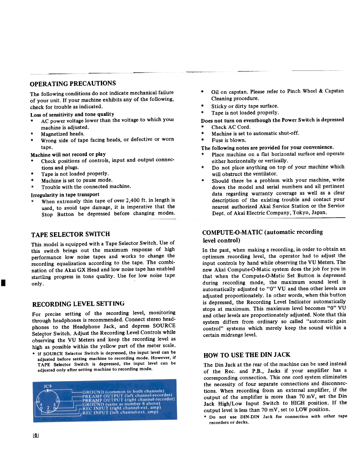
HOW TO USE THE DIN JACK
The Din Jack at the rear of the machine canbe usedinstead
of the Rec. and P.B., Jacks if your amplifier has a
corresponding connection. This one cord systemeliminates
the necessity of four separate connections and disconnec-
tions. When recording from an external amplifier, if the
output of the amplifier is more than 70 mY, set the Din
Jack High/Low Input Switch to HIGH position. If the
output levelis lessthan 70 mY, setto LOWposition.
* Do not use DIN-DIN Jack for connection with other tape
recordersor decks.
~
www.hifiengine.com

HEAD CLEANING
The GX Headsdo not normaliy require cleaning. However,
if old tapes or tapes which have beenspliced are used,head
cleaning is recommended. Clean by rubbing the entire head
surface (do not scratch)with acotton swabstick which has
beendipped in Akai cleaningfluid from Akai HeadCleaning
Kit HC-500.
PINCH WHEEL & CAPSTAN CLEANING
If foreign matter is allowed to accumulate on the Pinch
Wheeland Capstan,theseparticles will come off on the tape
causing deterioration of sound quality. Oil adhering to the
capstan also causes irregularity in tape transport. It is,
therefore, recommended that these parts be wiped clean
occasionally. For pinch wheel and capstan cleaning, use
Akai Cleaning Kit HC-500, or if this is not available,use
alcohol.
* Do not use chemicals such as chlorothane, etc., as the rubber
wheelwill deteriorate.
HEAD DEMAGNETIZING
Normally, the steel pole pieces which form part of the
recording and playback headsbecome slightly magnetized.
The effect of magnetization is that it causesconsiderable
drop-out or introduces noise into your recordings. It is,
therefore, recommended that head demagnetizing be per-
formed periodically. This can be accomplished with a bulk
head demagnetizer by bringing it close to the heads and
making severalcircular motions over all head surface areas
aswell asthe head housing.
.Be sure to cut off the power of the unit prior to demagnetizing
the heads.
.Do not use magnetized tools in the vicinity of the heads.
SOUNDMONITORING
This model is provided with aHeadphone Jackand Monitor
Selector Switches so that sound source or recorded signals
can be monitored. For monitoring P!ogram source during
recording, depressSOURCE Switch. If the TAPE Switch is
depressed,the recorded signals will be monitored as the
tape passesthe Playback Head. For private headphone
listening, connect an 8 .11impedance stereo headphoneand
depressTAPE Switch.
lIJ
www.hifiengine.com

TAPEERASING
Any signal information previously recorded on a tape will
be erased automatically as a new recording is made. For
erasing only, thread the tape and set machine to recording
mode. No plugs should be connected to the input jacks and
recording level controls should be kept at minimum. ,Akai
Tape Eraser ATE-7 is recommended for quick and complete
erasure.
TAPELOADING
Place a full reel of tape on the Supply ReelTable and an
empty reel on the Take-Up Reel Table. Thread the tape as
illustrated by the dotted lines in the figure anq lock reels
into place with the Reel Retainers provided on reel shafts.
4-TRACK STEREO
RECORDING/PLAYBACK SYSTEM
STEREO
I = I I I
Track1 .Stereo L1- Track1 L1-
2 R2-
-~ n~~
StereoAl-
;j
4 LOl-
I I
4-track stereo recording/playback system requires the
simultaneous use of two tracks. For stereo operation,
depressboth Track Selector Switches. The first recording/
playback takes place on tracks I and 3 and the second on
tracks 2 and 4 after the recorder has been set to reverse
mode.
4-TRACK MONAURAL
RECORDING/PLAYBACK SYSTEM
MONAURAL
Track1r=::.: ::JMono 1-.
2 4-
..-
~
;s ,,-
-4 -:l- r I
..I --I
4-track monaural recording/playback sequenceis 1-4-3-2.
For monaural operation, depress LEFT Track Selector
Switch. The first recording/playback takesplace on track 1
and the second on track 4 after the recorder hasbeen setto
reversemode. For recording/playback on track 3-2,depress
RIGHT Track Selector Switch. The third recording/
playback takes place on track 3 and the fourth on track 2
after the recorderhas beensetto reversemode.
[§]
AUTOMATIC & MANUAL REVERSE
RECORDING/PLA YBACK
For automatic reverse recording or playback, affix about a
2.5 cm (l'j long piece of metallic sensing foil to the
outside of the tape at desired reversing point. If continuous
reverse between two points is desired, affix another piece of
sensing foil to the inside of the tape at desired reversing
point. In other words, affix a piece of sensing foil at each
end of the tape (outside of tape for normal to reverse
operation, and inside of tape for reverse to normal
operation). As the sensing foil passes the sensing poles,
reverse is effected.
* Your machine is also equipped with a Manual ReverseKey for
your convenience.
For reference, see AUTOMATIC STOP & SHUT-QFF,
page4.
www.hifiengine.com

PLAYBACK OF PRE-RECORDED TAPE
A'-' ---~
-9
~~
y-
MONAURALPLAYBALK
Only the left channel is used for monaural playback.
Substitute the following steps for steps B, F, and G of
stereo playback procedure.
Tracks 1-4
B. DepressLEFT Track SelectorSwitch.
F. Adjust left Line Output Level Control and external
amplifier controls.
G. DepressREV Key for playback on track 4.
Tracks 3-2
B. DepressRIGHT Track SelectorSwitch.
F. Adjust left Line Output Level Control and external
amplifier controls.
G. DepressREV Key for playback on track 2.
Please read the operating precautions carefully before
attempting operation. Connect the Line Oqtputs of the
GX-370D to the tape inputs of the external amplifier and
connect tw~ speakersto the amplifier. Connect power cord
and load a pre-recorded tape;
STEREO PLAYBACK
A. Turn on PowerSwitch.
B. Depress both LEFT and RIGHT Track Selector
Switches for stereooperation.
C. Selecttape speed.
D. DepressTAPE Monitor Switch.
E. DepressFWD Key to beginplayback.
F. Adjust left and right Line Output Level Controls and
external amplifier controls.
G. DepressREV Key for reverseplayback.
H. DepressSTOPKey to stop playback.
~
www.hifiengine.com

RECORDINGUSING MICROPHONES
MONAURAL RECORDING
Only the left channel is used for monaural recording.
Substitute the steps B, E, G and J of stereo recording
procedure for the following step~.
Tracks 1-4
B. DepressLEFT Track SelectorSwitch.
E. Insert microphone into left Microphone Jack.
G. Adjust and balance recording input level with left
Microphone Recording Level Control while observing
the left VU Meter.
J. For reverse recording on track 4, while holding
Recording Safety Button at depressedposition, depress
REV Key.
Tracks 3-2
B. DepressRIGHT Track SelectorSwitch.
E. Insert microphone into left Microphone Jack.
G. Adjust and balance recording input level with left
Microphone Recording Level Control while observing
the left VU Meter.
J. For reverse recording on track 2, while holding
Recording Safety Button at depressedposition, depress
REV Key.
Please read the operating precautions carefully before
attempting operation. Connect power cord and load atape.
STEREO RECORDING
A. Turn on PowerSwitch.
B. Depressboth LEFT and RIGHT Track Selector Switch
for stereooperation.
C. Selecttape speed.
D. Set Index Counter to "0000". This provides an easy
reference for locating positions on the tape.
E. Insert microphones into left and right Microphone
Jacks. Maintain a distance of at least 2 meters (7 ft.)
betweenmicrophones.
F. DepressSOURCE Monitor Switch.
G. Adjust and balance recording input level with left and
right Microphone Recording Level Controls while
observing corresponding VU Meters. Normal recording
levelshould not exceed "0" VU.
H. Whenan optimum recording levelhasbeen determined,
while holding Recording Safety Button at depressed
position, depress FWD Key to begin recording. Note
that the Recording Indicator Lamp will light.
I. To stop recording depressStop Key.
J. For reverserecording, while holding Recording Safety
Button at depressedposition, depressREV Key.
I1Q/
www.hifiengine.com

RECORDING FROM AN EXTERNAL
AMPLIFIER
If an external amplifier or tuner amplifier is used, connect
the tape outputs of the external amplifier to the Line
Inputs in stepE of stereorecording procedure.
RECORDING FROM A TURNTABLE
To record from a stereo or monaural disc,a crystal pick-up
can be connected directly to the Line Inputs in step E of
stereo recording procedure. If a magnetic or similar
cartridge is used, it must be connected to the Line Inputs
through an external amplifier.
TAPEDUBBING
Whendubbing tape from another recorder, connect the line
outputs of playback machine to the line inputs of the
recording machine in step E of stereo recording procedure.
SOUND-ON-SOUNDRECORDING
For transfer of previously recorded material from one track
to another accumulating asmany individual recordings on a
single track as is desired. Use for language training or
variousinteresting musicalcompilations.
First Recording
A. Turn on PowerSwitch. The Power Indicator Lamp will
light.
B. Confirm that there are no connections to the Line
Input Jacks.
C. With the Reset Button set the Index Counter to
"0000".
D. DepressLEFT Track SelectorSwitch.
E. Insert microphone into left Microphone Jack.
F. DepressSOURCE Monitor Switch.
G. Adjust left Microphone Recording Level Control while
observingleft VU Meter.
H. While holding Recording Safety Button at depressed
position, depress FWD Key. to begin first recording;
i.e.,DO-RE-MI.
I. When the first recording is complete, rewind tape to
starting point.
the Din connector to the Din Jack and the black cord
Pin Plug to the left Line Input Jack.
SecondRecording
J. Depressboth Monitor Switches.
K. DepressRIGHT Track SelectorSwitch.
L. IncreaseLine Recording LevelControl.
M. Connect stereo headphonesto monitor first recording
on track 1.
N. While holding Recording Safety Button at depressed
position, depressFWD Key to begin secondrecording;
i.e., MI-FA-SOL.
O. Reset left Line Recording Level Control (decreaselittle
by little) until proper levelis obtained.
The second recording is made. on track j as the rust
recording is monitored through headphones. The two
recordings. will be completely merged on track 3 ; i.e.,
DO-MI-RE-FA-MI-SOL.
Third and subsequentrecordings are made in the sameway
by switching LEFT and RIGHT Track Selector Switches.
For playback, set Track Selector Switch to track on which
last recording was made and depress the TAPE Monitor
Switch.
With the standard accessoryl:onnection l:ord connect
I!1J
www.hifiengine.com

SOUNDMIXING
For mixing microphone and line input signals, proceed as
follows:
A. Insert microphones into Microphone Jacks and connect
the line outputs of external source to the Line Input
Jacks.
B. Adjust microphone input level with Microphone
Recording Level Controls and line input level with Line
Recording Level Controls.
C. For playback, operate Track Selector Switch according
to tracks used in making recording.
SOUND-WITH-SOUNDRECORDING
Sound-with-sound recording is accomplished in the same
way as Sound-On-Sound except that instead of transferring
from one track to another, the sound on track 1 is
monitored through headphones while the second recording
is made on track 3. This feature is especially convenient for
teacher/student repetition and comparison (teacher's voice
on track 1 and student's voice on track 3. For sound-with-
sound recording, follow Sound-On-Sound recording proce-
dure, substituting the following step for step L, and
eliminating step O.
L. Decrease Line Recording Level Control to minimum.
For playback, depress both Track Selector Switches (for
stereo) and depress the TAPE Monitor Switch.
TAPE SPLICING & EDITING
Cut tape diagonally with an overlap so that the ends are
lined up. Cutting tape on diagonal eliminates detection of
splice in recording. Cover aligned ends with splicing tape.
Press firmly exerting pressure to secureends evenly. Trim
off excesssplicing tape cutting into tape very slightly. This
eliminates the possibility of a sticky splice. For easyand
smooth tape splicing, Akai Tape Splicer AS-3 is highly
recommended.
~
~
www.hifiengine.com

TECHNICAL DATA
Track System.
ReelCapacity.
Tape Speed. ..
Wow& Flutter
..4-track 2-channelstereo/monaural
..Up to 7" reel
..7-1/2 and 3-3/4 ips (:to.5%)
..Less than 0.07% RMS at 7-1/2 ips
Lessthan 0.10% RMS at 3-3/4 ips
..Correct equalization for playback
of tapesrecorded to NAB curve.
..(Using Akai SRT Tape) : 20 Hz to
26,000 Hz (:t3 dB) at 7-1/2 ips,
30 Hz to 22,000 Hz (:t3 dB) at
3-3/4 ips. (Using Regular Tape):
20 Hz to 24,000 Hz (:t3 dB) at
7-1/2 ips, 30 Hz to 19,000 Hz
(:t3 dB) at 3-3/4 ips
..0.8% (1,000 Hz "0" VU) using
Akai SRTTape
Equalization
Frequency Response
Distortion
Signal- To-Noise
Ratio.Erase Ratio. ..
Bias Frequency
Heads.
58 dB using Akai ~Kr rape
Better than 70 dB
100 kHz
(3): Two GX combination recording
& eraseheads,one GX
playback head
(3): 2-speedservo-control outer-
J"otormotor for direct capstan
drive, and two 6-pole eddy-
current outer rotor motors for
supply and take-up reeldrive.
Motors
.tor improvement purposes, specitlcations and designare subject
to changewithout notice. ~
www.hifiengine.com

STANDARD ACCESSORIES
1
1
1
.1 set
1
Connection Cord.EmptyReelSensing TapeSpare FuseOperator's Manual.
.Spare fuses are not included with CEE, CSA, and UL Standard
models.
OPTIONAL ACCESSORIES
ATE-7
DM-13
UM-IO1
TapeEraser
Urn-DirectionalDynamicMicrophone Non-DirectionalDynamicMicrophone
-
AS-3
RC-16
RemoteControl TapeSplicer
ASE-:lU
ASE-22
StereoHeadphones Stereo Headphones
~
www.hifiengine.com

Stereo Pre-MainAmplifier
L
www.hifiengine.com

MANUFACTURED & DISTRIBUTED BY
AKAI ELECTRIC CO., LTD.
AKAI TRADING CO., LTD.
12.14, 2.chome, Higashi.Kojiya,
Ohta.ku, Tokyo, Japan
AKAI AMERICA LTD.
2139 E. Del Amo Blvd., Compton, Calif., 90220, U.S.A.
TEI.EPHONE: (213) 537.3880
TEI.EX: 67.7494
:',,.,,{:.
.
_:~ ,"
,-
-
,~:,:~i;;~
Printed in Japan
Price US $1.50
~
www.hifiengine.com
Other manuals for GX-370D
1
Table of contents
Other Akai Tape Deck manuals