manuals.online logo
Brands
  1. Home
  2. •
  3. Brands
  4. •
  5. Teac
  6. •
  7. Tape Deck
  8. •
  9. Teac Tascam 3030 User manual

Teac Tascam 3030 User manual

Other Teac Tape Deck manuals

Teac X-3 User manual

Teac

Teac X-3 User manual

Teac A-6100 User manual

Teac

Teac A-6100 User manual

Teac A-6100 User manual

Teac

Teac A-6100 User manual

Teac A-3300SR User manual

Teac

Teac A-3300SR User manual

Teac X-3 User manual

Teac

Teac X-3 User manual

Teac A-6010GSL User manual

Teac

Teac A-6010GSL User manual

Teac X-300R User manual

Teac

Teac X-300R User manual

Teac A-2340 User manual

Teac

Teac A-2340 User manual

Teac X-3R User manual

Teac

Teac X-3R User manual

Teac A-3340 User manual

Teac

Teac A-3340 User manual

Teac A-6010GSL User manual

Teac

Teac A-6010GSL User manual

Teac A-6010SL User manual

Teac

Teac A-6010SL User manual

Teac A-4070G User manual

Teac

Teac A-4070G User manual

Teac A-2340 User manual

Teac

Teac A-2340 User manual

Teac A-3300 User manual

Teac

Teac A-3300 User manual

Teac A-1250S User manual

Teac

Teac A-1250S User manual

Teac A-6600 User manual

Teac

Teac A-6600 User manual

Teac X-300R User manual

Teac

Teac X-300R User manual

Teac X-7RMKII User manual

Teac

Teac X-7RMKII User manual

Teac A-3440 User manual

Teac

Teac A-3440 User manual

Teac A-6300 User manual

Teac

Teac A-6300 User manual

Teac A-3440 User manual

Teac

Teac A-3440 User manual

Teac X-1000M User manual

Teac

Teac X-1000M User manual

Teac A-7300RX User manual

Teac

Teac A-7300RX User manual

Popular Tape Deck manuals by other brands

Pioneer RT-1020L operating instructions

Pioneer

Pioneer RT-1020L operating instructions

3M 3M-Matic Dual S-867 II Instructions and parts list

3M

3M 3M-Matic Dual S-867 II Instructions and parts list

Pioneer GT-X5 Service manual

Pioneer

Pioneer GT-X5 Service manual

SilverStone 1232 manual

SilverStone

SilverStone 1232 manual

Hitachi D-980MU Service manual

Hitachi

Hitachi D-980MU Service manual

Hitachi D-900BS Service manual

Hitachi

Hitachi D-900BS Service manual

Kyocera D-611 Service manual

Kyocera

Kyocera D-611 Service manual

Kenwood KX-W595 instruction manual

Kenwood

Kenwood KX-W595 instruction manual

TANDBERG 11 instruction manual

TANDBERG

TANDBERG 11 instruction manual

Sony DTC-670 operating instructions

Sony

Sony DTC-670 operating instructions

Pioneer H-R99 KCU Service manual

Pioneer

Pioneer H-R99 KCU Service manual

Kenwood KX-W6070 instruction manual

Kenwood

Kenwood KX-W6070 instruction manual

Sony DTC-A8 Service manual

Sony

Sony DTC-A8 Service manual

Tascam BR-20 Series maintenance

Tascam

Tascam BR-20 Series maintenance

Kenwood KX-620 instruction manual

Kenwood

Kenwood KX-620 instruction manual

uher SG 560 Royal Servise manual

uher

uher SG 560 Royal Servise manual

Kenwood KX-9050 instruction manual

Kenwood

Kenwood KX-9050 instruction manual

Technics SV-DA10 operating instructions

Technics

Technics SV-DA10 operating instructions

manuals.online logo
manuals.online logoBrands
  • About & Mission
  • Contact us
  • Privacy Policy
  • Terms and Conditions

Copyright 2025 Manuals.Online. All Rights Reserved.

www.SteamPoweredRadio.Com
TASCAM
TEAC
Professional Division
StereoTape Deck
(
___
O_W_N_E_R_'S_M_A_N_U_A_L
__
)
5700110400
www.SteamPoweredRadio.Com
The guarantee provided for
the
3030
has several
restrictions.
The
3030
will
perform
properly
only if it
is
adjusted properly
and
we guarantee
that
such adjust-
ment
is
possible.
Setup
is
not
covered by Warranty.
If
your
attempts
at
internal
adjustments
are unsuccessful,
we
will
charge you for readjustments.
Recording
is
an
art
as
well as a science.
As
a result,
your
finished
product
may be judged more by artistic
criteria than technical performance.
Art
is
the
province
of
the
artist
and
TASCAM
can
make
no
guarantee
that
the
3030,
by
itself,
will assure
the
quality
of
your
work.
Your skill
as
a technician
and
your
abilities
as
an
artist
will
be significant factors in
the
results
you
achieve.
Bescheinigung des Herstellers/lmporteurs
Hiermit
wird
bescheinigt
,
da8
der
/
die
/
das
MAGNETTONBANDGERAT TASCAM 3030
(Ger
a.
t,
Typ,
B
ezeic
hnung)
in
Obereinstimmung
mil
den
Bestimmungen
der
AMTSBLATT
163/1984,
VFG
1045/1984,
VFG
1046/1984
(A
m
ts
blattverfOgung)
funk-entstOrt
isl.
Der
Deutschen
Bundespost
wurde
das
lnverkehrbringen
dieses
Ger/Hes
angezeigt
und
die
Berechtigung
zur Ober-
prOfung
der
Serie auf Einhaltung
der
Bestimmungen eingerlo\umt.
TEAC CORPORATION
Name des Herste
ll
ers/lmporteurs
This
product
is
manufactured
to
comply
with
the
radio interference
of
EEC directive
"82/499/EEC
."
A
~
CAUTION
J A
~
ltt111iMl1illlti
~
CAUTION:
TO
REDUCE
THE
RISK
OF
ELECTRIC
SHOCK,
DO
NOT
REMOVE
COVER
(OR
BACK)
.
NO
USER-SERVICEABLE
PARTS
INSIDE.
REFER
SERVICING
TO
QUALIFIED
SERVICE
PERSONNEL.
A
The
lightning
flash
with
arrowhead
symbol,
within
an
equilateral
triangle,
is
intended
to
alert
the
user
to
the
presence
of
uninsulated
"dangerous
voltage"
within
the
product's
enclosure
that
may
be
of
sufficient
magnitude
to
constitute
a
risk
of
electric
shock
to
persons
.
The
exclamation
point
within
an
equilateral
triangle
is
intended
to
alert
the
user
tothe
presence
of
important
operating
and
maintenance
(servicing)
instructions
in
the
literature
accompanying
the
appliance
.
This
appliance
has
a
serial
number
located
on
the
rear
panel.
Please
record
the
model
number
and
serial
number
and
retain
them
for
your
records
.
WARNING:
TO
PREVENT
FIRE
OR
SHOCK
HAZARD,
DO
NOT
EXPOSE
THIS
APPLIANCE
TO
RAIN
OR
MOISTURE.
Model
number
___
_
___
_
Serial
number
-2-
t
www.SteamPoweredRadio.Com
'5
AFETY
INSTRUCTIONS
CAUTION:
• Read all
of
these instructions.
•
Save
these instructions
for
later
use.
• Follow all warnings and instructions marked
on
the
audio equipment.
•
1.
Read
Instructions
-All
the
safety and operating instructions
should be read before
the
appliance
is
operated.
2. Retain Instructions -The safety and operating instructions
should be retained for future reference.
3. Heed
Warnings
-All warnings
on
the appliance and
in
the
operating instructions should be adhered to.
4. Follow lmtructions -
All
operating and use instructions
should be followed.
5. Water
and
Moisture -The appliance should
not
be used
near water -for example, near a
bathtub,
washbowl, kitchen
sink, laundry tub,
in
a
wet
basement, or near a swimming
pool, etc.
6. Carts
and
Stands
-
The
appliance should be used only with
a
cart
or
stand
that
is
recommended
by
the manufac.turer.
&A.An
appliance and
cart
combination should be moved with
care. Quick stops, excessive force, and uneven surfaces may
cause the appliance and
cart
combination
to
overturn.
7. Wall or Ceiling Mounting -
The
appliance should be
mount
-
ed
to
a wall
or
ceiling only
as
recommended by
the
manu-
facturer.
8. Ventilation -The appliance should be situated so
that
its
location
or
position does
not
interfere with its proper venti·
lation.
For
example,
the
appliance should
not
be situated
on a bed, sofa, rug,
or
similar surface
that
may block the
ventilation openings;
or
, placed
in
a built-
in
installation,
such
as
a bookcase
or
cabinet
that
may impede
the
flow
of
air through the ventilation openings.
9. Heat -The appliance should be situated away from
heat
sources such
as
radiators, heat registers, stoves,
or
other
appliances (including amplifiers)
that
produce
heat
.
10.
11.
12.
Power
Sources
-
The
appliance should be connected
to
a
power supply only
of
the
type
described
in
the
operating
in-
structions
or
as
marked on
the
appliance.
Grounding or Polarization -
The
precautions
that
should
be taken so
that
the
grounding
or
polarization means of
an
appliance
is
not
defeated.
Power-Cord Protection -Power-supply cords should be
routed so
that
they
are
not
likely
to
be walked on
or
pinch-
ed by items placed upon
or
against them, paying particular
attention
to
cords
at
plugs, convenience receptacles, and
the
point
where they exit from
the
appliance.
Cleaning -The appliance should be cleaned only
as
recom-
mended by
the
manufacturer.
14. Power
Lines
-An
outdoor
antenna should be located away
from power lines.
-3-
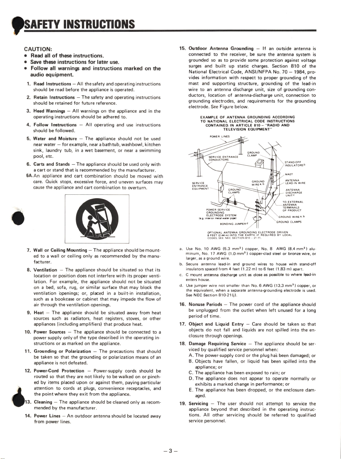
15. Outdoor Antenna Grounding -If an outside antenna
is
connected
to
the
receiver, be sure the antenna system
is
grounded so
as
to
provide some protection against voltage
surges and built up static charges. Section
810
of
the
National Electrical Code, ANSI/NFPA No.
70
-1984, pro-
vides information with respect
to
proper grounding
of
the
mast and supporting structure, grounding of the lead-in
wire
to
an antenna discharge unit, size of grounding con-
ductors, location
of
antenna-discharge unit, connection
to
grounding electrodes, and requirements for the grounding
electrode. See Figure below.
EXAMPLE
OF
ANTENNA GROUNDING ACCORDING
TO
NATIONAL
ELECTRICAL
CODE
INSTRUCTIONS
CONTAINED. IN ARTICLE 810 -"'RADIO AND
TELEVISION EQUIPMENT"'
(e
.g.
i
nter
ior
metal
water
pipe)
STANO-OFF
INSULATORSb
MAST
ANTENNA
LEAD
-
IN
WIRE
ANTENNA
--,,..,,"
· - -
B~1\~
AAGE
TO
EXTERNAL
ANTENNA
TERMINALS
OF PRODUCT
GROUND
WIRE•,
b
GROUND
CL
AMPS
OPTIONAL
ANTENNA
GROUNDING
ELECTRODE
DRIVEN
8
FEET
(2,_..
ml
INTO
THE
EARTH
IF
AEO
Ul
RED
BY
LOCAL
CODES. SEE
NEC
SECTION
810
-
21
!fl
.
a.
Use
No.
10
AWG
(5.3
mm
2)
copper,
No
. 8
AWG
(8.4
mm')
alu-
minum,
No
.
17
AWG
(1
.0
mm
2)
copper-clad
steel
or
bronze
wire,
or
larger,
as
a
ground
wire
.
b. Secure
antenna
lead-in and
ground
wires
to
house
with
stand-off
insulators
spaced
from
4
feet
(1
.22
m)
to
6
feet
(1.83
m)
apart
.
c. C
mount
antenna
discharge
unit
as
close
as
possible
to
where
l1111d-in
enters
house
.
d. Use
jumper
wire
not
smaller
than
No
. 6
AWG
(13.3
mm
2)
copper,
or
the
equivalent,
when
a separate
antenna-grounding
electrode
is
used.
See
NEC
Section
810-21(j)
.
16. Nonuse
Periods
-The power cord
of
the
appliance should
be unplugged from
the
outlet
when left unused for a long
period
of
time.
17. Object
and
Liquid Entry -Care should be taken so
that
objects
do
not
fall and liquids are
not
spilled into the en-
closure through openings.
18. Damage Requiring
Service
-The appliance should be ser-
viced
by
qualified service personnel when:
A.
The
power-supply cord
or
the
plug has been damaged; or
B.
Objects have fallen, or liquid has been spilled into the
appliance;
or
C.
The appliance has been exposed to rain; or
D.
The
appliance does
not
appear
to
operate normally or
exhibits a marked change
in
performance;
or
E.
The
appliance has been dropped,
or
the enclosure dam-
aged.
19. Servicing -
The
user should
not
attempt
to
service the
appliance beyond
that
described
in
the
operating instruc-
tions.
All
other
servicing should be referred
to
qualified
service personnel.
www.SteamPoweredRadio.Com
Introduction
The
TASCAM
3030
incorporates a
variety
of
functions
and
features
including
dbx
Noise
Reduction
(Type
I),
an
Auto-Locator
func-
tion
which
is
convenient
in
replay
and
editing
and
block
repeat.
To
maintain
very
stable
tape
motion
with
optimum
tape
tension,
it
uses
a
full
tension
servo
control
system
in
which
a photo-interrupter
senses
the
position
of
the
tension
arm
so
that the
servo
mechanism
can
adjust
the
torque
of
the
reel
motor.
Th
is
mechanism
eliminates
the
need
for
manual
switching
when
using
different
types
of
reels.
In
the
design
of
the
electronic
circuits
the
same
concepts
wire
applied,
especially
for
the
high
level
recording
required
by
professionals.
So
that
you
get
the
best
possible
results
from
your
dee
k
and
realize
its
tu
II
potential
as
a
master
tape
deck,
please
read
this
manual
carefully.
Table
of
Contents
Introduction
. . . . . . . . . . . . . . . . 4
Specifications
. . . . . . . . . . . . . . . . 4
Block
and
Level
Diagrams
. . . . . . . . . 5
Pre-operating
Procedures
. . . . . . . . . 6
Operation
Getting
Started . . . . . . . . . . . . . 8
Using
the Auto-Locator Function . . 8
Block
Repeat
Operation
. . . . . . . . 8
Auto-skip
Playback
Operation
. . . . 9
Dubbing
.................
9
Dubbing
with
DUPLI
SYNC
. . . . . 9
Spooling
. . . . . . .
..........
10
Monophonic
Recording/Playback
. . 1O
Sound-on-sound
Recording
......
10
Using
the
BIAS
FINE
Control
....
10
Erasing
................
..
10
Features
and
Controls
...........
11
HowthedbxWorks
...........
.
15
Maintenance
................
15
Optional
Equipment
............
16
Specifications
MECHANICAL
CHARACTERISTICS
Tape
Format
2-track,
2-channel
recording/
reproduce
4-trak,
2-channel
reproduce
Max.
Reel
Size
10-1/2",
NAB
hub
Tape
Speed
38
cm/s
(15
ips)
and
19
cm/s
(7.5
ips)
Speed
Accuracy
±0.5
%
deviation
Pitch
Control
±6 %
Wow
and
Flutter
±0.07
%
peak
weighted
(DIN
45507)
at
15
ips,
±0.08
%
peak
weighted
(DIN
45507)
at
7.5
ips
Fast
Wind
Time
approx.
100
sec.
for
1,800
ft
.
Motors
Capstan
FG
servo
DC
motor
Reel
2
DC
slotless
motors
Head
Configuration
4
heads;
2-track
2-channel
erase,
record,
reproduce
and
4-track
2-channel
reproduce
Dimensions
432
x
456
x
268
mm
(17" x
17-5/16"
X
10-9/16")
Weight
(net)
21
kg
(46
-5/16
lbs)
ELECTRICAL
CHARACTERISTICS
Mic
Input
Input
Impedance
10
kohms,
balanced
Applicable
Mic
Impedance
200
ohms
or
more
Minimum
Input
Level
-72
dVB
(0.25
mV)
Line
Input
Balanced/
Unbalanced
Input
Impedance
10
kohms/
50
kohms
Maximum
Source
Impedance
2
kohms/10
kohms
Nominal
Input
Level
+4
dBm
(1.23
V)/-10
dBV
(0.3
V)
Maximum
Input
Level
+28
dBm
(19
.5
V)/
+18
dBV
(8.0
V)
Line
Output
Balanced/
Unbalanced
Output
Impedance
100
ohms/
500
ohms
Minimum
Load
Impedance
600
ohms/
3
kohms
Nominal
Load
Impedance
10
kohms/
10
kohms
Nominal
Output
Level
+4
dBm
(1.23
V)/-10
dBV
(0.3
V)
Maximum
Output
Level
+28
dBm
(19
.5
V)/
+18
dBV
(8.0
V)
Headphone
Output
Level
(where
applicable)
50
mW
max.
into
8
ohms
Bias
Frequency
150
kHz
Equalization
3,180
+
50
µsat
15
ips
and
7.5
ips
Operating
Level
320
nWb/m
or
250
nWb/m
switchable
-4-
Power
Requirements
USA/CANADA
120
V
AC,
60
Hz
U.K./AUSTRALLIA
240
V
AC,
50
Hz
EUROPE
220
V
AC,
50
Hz
GENERAL
EXPO
RT
100/120/220/240
V
AC,
50/60
Hz
Power
Consumption
120
Watts
TYPICAL
PERFORMANCE
Frequency
Response
(Record/Reproduce)
40
Hz
-
22
kHz
±2
dB
(OVU,
15
ips)
30
Hz
-
20
kHz
±2
dB
(-10
VU,
7.5
ips)
Total
Harmonic
Distortion
(THD)
0.6%at0VU,
1
kHz
Signal-to-Noise
Ratio
(overall)
(Referenced
3 %
THD
at
1
kHz)
dbx-in
98
dB
(NAB
A
Weighted)
at
15
and
7.5
ips
dBx-out
68
dB
(NAB
A
Weighted)
at
15
and
7.5
ips
Adjacent
Channel
Crosstalk
better than
55
dB
(1
kHz)
Erasure
better
than
70
dB
(1
kHz,
+10
VU)
In
these
specifications,
0
dBm
is
referen
.
to
0.775
Volt.
0
dBV
is
referenced
1.0
Volt
.
Actual
voltage
levels
are
also
gi
in
parentheses.
Changes
in
specifications
and
features
may
be
made
without
notice
or
obligation.
dbx
is
a trademark
of
dbx
Incorporated.
www.SteamPoweredRadio.Com
I
(J1
I
REPR
ODUCE
HEAD
+34dB
(Q301
'\t0309)
()
R554
OBX LEVEL
R32B
B
AL.
IN AM
P.
MIXING
AMP.
LINE
AMP
.
:-1
NPuf
~L
_____
_J
(BALANCE)
R110
[I
~~uJ
=J
(U
NBALANCE)
~· ~
~
(d
BV I
+10
0
-10
-20
-30
-40
·~~
P,B
-60
- ?O
-I
M
IC
,-72.2dBV
- 70 dBm )
-80
I
ITi:ED
-14,
SdBV
MIC
VR01 (
MA
X)
LINE
V
R02
-
25dBV
-30,2dBV
-5
0dBV
-55dBV
R361
+20.BdB
PLAY LINE
AMP
.
(U
301-II
oex
LEVEL
R365
R557
OUT
S306
t
DkIJ
IN
MIXING
AMP
II
PHASE AMP,
DBX
ENCOD
ER
I
U305
l
(U
327
l
-25dBV
I
R585
R586
U31
4
(ON l
-39dBV
R556
OUTPUT
LEVEL
S303
TAPE
MONITOR I l
R369
R373
R559
REC
LEVEL
R375
-4,2dBV
(-2d
Bml
-21dB
V
REC
LEVEL
R559
-33dBV
SOURCE
R371
R556
OUTPUT
LEVEL
• 0 dBV = 1V
+10dB
R345
'-''-''''-''""""·
{ U3
0l-2)
R370
• 0 dBm =
0.775V
I
-
R350
,j,
I ll -
~ ·
,I,
+6dB
C
H2~~
PHON
E
AMP.
(U
309
,
0319,0323)
+4d8m
-10d8V
-36
,5
dBV
• REFERENCE
LEVEL
250
nWb/m
ot
1 kHz
(0
VU
I
[q
~T_PQf
J
IUNBALANCE I
[§
~-
,:_P~!
J
{
BA
LA
NCE
)
I
PHON
ES I
( 1omw1en1
VU
METER
(
OVUl
RECORD
HEAD
OUTPUT
( BALANCE)
OUTPUT
(
UN
BALANCE l
RE
CORD
HE
AD
n
,-:-
I»
=
Cl.
,-
~
!!!.
C
ii"
Cl
...
I»
3
"'
www.SteamPoweredRadio.Com
Pre-operating
Procedures
t
______________________________________
,,_.
r-
.,
_
---
/
.
1.
Unpacking
and
Inspection
During
unpacking,
be
careful
not
to
damage
the 3030.
Save
the
carton
and
packing
mater
i
als.
You
may
need
them
to
transport
your 3030 at
some
time
in
the future. After
unpacking
check
the
unit for
any
evidence
of
damage
due
to
rough
handling
during
shipment. Contact your dealer
if
you
have
any
questions.
2.
Environmental
Co
nd
itio
ns
The
3030
may
be
used
in
most
areas,
but to
ma
i
ntain
top performance
and
prolong
op-
e
rating
life,
observe
the
following
environ
-
mental
limitations:
1)
Nominal
temperature
should
be
5
to
35
degrees
C
(41
to
95
degrees
F).
2)
Relative
hum
idity
should
be
30
to
90
%
(non-condensing)
.
3)
Strong
magnetic
fields
should
not
exist
nearby.
3.
Rack
Mounting
the
3030
The
3030
may
be
mounted
to a standard
EIA
19''
rack,
such
as
the
TASCAM
CS-
607B
,
using
the
optional
RM-10A
mount
br
acket.
4.
Initial
Connections
CAUTION:
Before
attempting
any
cable
connection,
check
to
make
sure
that
all
the
units
involved
in
your
system
are
turned off.
Headphones
3030
AUX
or
()
©a
~©a
{j u
_
o~b.
0
.
Hilllllllilllfi~
□
mmmm~<!immrn
□
mc1iG>t!i@===
Multi·
STEREO
OUT
Mixer
track
OUTPUT
LINE
IN
TAPE
MONITOR
Monitor
Amp
Monitor
Speaker
5.
Reel
Installation
c_)
- 6 -
Monitor
Speaker
It
;,
,;1a1
lo
'"""
tho
,.,,,
famly
to
.
reel
tables. 7-
inch
reels
are
clamped
directly
using
the
"OUIK
-
LOK"
reel
holders.
Turn
·
i
ng
the
top
part
of
the
reel
holders counter-
clockwise
lines
up
the
tabs
so
that
reels
can
be
inserted
and
removed
.
Turn
the
top
portion
clockwise
to
"unalign"
the
tabs
and
lock
the
reel
onto the
reel
table.
Large
diameter
10-1/2
inch
reels
have
large
center
holes
and
cannot
be
used
directly
on
the
reel
tables.
First
you
must
fit
the
supplied
reel
adaptors
in
exactly
the
same
way
as
ordinary
reels
.
When
the
reel
adaptor
is
firmly
in
place
, the
large
reels
can
be
mounted
as
follows
:
1.
Rotate the outer part
of
the
adaptor
fully
counterclockwise.
This
will
line
up
the
small
tabs
which
fit
into
the
three
notches
in
the
reels
.
2.
Insert
the
reels
and
rotate
the
outer
part
of
the
-adaptor
clockwise
.
This
will
"unalign" the
tabs.
www.SteamPoweredRadio.Com
'
3. Continue turning
the
outer part
clock
-
wise
until
the
tabs
are
drawn
down
tightly onto
the
reels.
4.
Reels
can
be
removed
by
reversing
the
above
procedure.
Note:
A
metal
spacer
is
mounted
on
the
back
of
these
reel
adaptors
and
it
must
be
in
place
when
NAB
standard
10
-1/2
inch
metal
reels
are
used
.
For
large
plastic
reels,
this
spacer
must
be
re
-
moved
. It
twists
out
and
twists
in
quite
easily
.
Caution
:
Be
carefu
I
not
to
fasten
the
tape
to
the
reels
with
reel
holders
(reel
adaptors).
The
tape
ends
must
be
re
-
leased
easily
from
the
reels,
otherwise
high
inertia torque
will
be
applied
when
the
ends
of
tape
is
reached
in
fast-
forwa
rd
or
fast
-
rewind
which
could
damage
the
tape
transport
mechanism
.
6.
Voltage
Conversion
For
General
Export
Model
only:
When
it
is
necessary
to
change
the
voltage
'
!rt
this
tape
deck
to
match
that
in
your
area,
the
following
procedure
:
ALWAYS
CONNECT
POWER
LINE
CORO
FORE
MAKING
THESE
CHANGES
.
1.
F
1rst
remove
the
two
feet
by
removing
the
screws
in
each
one
.
2.
Unscrew
the
left
and
right
sides
of
the
cabinet.
3.
Remove
the cabinet and locate the
voltage
selector
as
seen
from
the top
side
of
the
deck.
4.
Turn
the
· slotted center post
of
the
selector
with
a screwdriver to
match
the
numerals
corresponding
to
the
voltage
requirement
of
your
area
to
the point
marked
"SET
UP
VOLTAGE"
(click
sound
is
heard) .
5.
Replace
the cabinet
and
feet.
Voltage
selector
0
VOLTAGE
SELECTOR
PCB
O
-7-
www.SteamPoweredRadio.Com
Operation
A
1
-------~
-
Getting
Started
1.
Setting
the
Record
Level
1.
With
the
POWER
switch
OFF,
connect
the
source
you
want
to
record
to
an
ap•
propriate jack/connector.
If
your
source
is
a microphone or
an
instrument
such
as
an
electric guitar,
choose
a
MIC
jack
on
the front
panel.
With
a
line
level
source
such
as
an
output
from
synthesizers,
tuners
or
multitrack recorders,
use
a
rear
panel
INPUT
RCA
jack
or
XLR
type
connector.
2.
Plug
in
stereo
headphones, but don't put
them
on
yet.
3.
Check
to
make
sure
that
all
the
level
controls,
MIC,
LINE
and
OUTPUT,
are
turned
fully
counterclockwise
(to
MIN
position), then turn the 3030
on
by
pressing
the
POWER
switch.
4.
Produce
the type
of
sound
you
want
to
record.
You
may
want
to try
the
follow
-
ing:
For
your
mic,
use
a portable
radio
as
a
source
of
sound
. Select a station broadcast-
ing
the type
of
material
you
want
to
record
,
and
experiment
with
mic
positioning.
When
you
want
to
record
an
organ,
you
can
weigh
down
a
key
or
wedge
piece
of
cable
between
keys
for
a continuous
sound
.
With
synthe-
sizers
you
can
use
LF0
trigger
modes
or
hold
functions. Finally,
we
come
to
actual
record
level
setting.
5.
Gradually
turn the
LINE
or
MIC
level
control
up
to
around ''7"
on
the
scale.
If
at this "nominal" setting the
VU
meters
does
not
peak
at around 0
VU,
adjust
the
volume
of
your source.
6.
Put
on
the
headphones
and
turn
up
the
0
UTPUT
level
control
until
the
desired
listening
level
is
achieved
over
the
head
-
phones
or
monitor speaker
system
.
2.
Recording
the
First
Track(s)
1.
Turn
off
the
power
and
connect your
source
to
MIC
jack(s)
or
Line
INPUT
connector{s)
.
2.
With
connections
made,
turn
on
power
again.
3.
Reset
the
tape counter
to
zero
so
you
will
know
where
your
recording
began,
and
press
the
RTZ
(Return
To
Zero)
button.
4.
Press
the
REC
FUNCTION
k11y
or
keys
depending
on
your source connection.
The
RECORD
LED
will
begin
blinking
.
Before
performing
the
next
step
check
to
see
the
fol
lowing
are
set
to
the
ap-
propriate positions:
1)
TIMER
(Off),
2)
SPEED
(HIGH
or
LOW),
3)
AUTO
SPACER
(see
"Features
and
Controls" #
13),
4)
PITCH
CON-
TROL
(Off)
,
5)
dbx
1
(IN
or
OUT),
6)
REF
LEVEL
(see
"Features
and
Con-
trols", #
27)
5.
Press
the
RECORD
and
Play
buttons
simultaneously
to
start
recording.
The
RECORD
LED
that
was
blinking
will
go
on
solid.
6.
Press
the
OUTPUT
monitor
key(s)
to
set
them
to
REPRO
position.
The
monitor
will
switch
from
source
to
tape.
When
recording
is
complete,
press
RTZ.
The
tape
will
rewind
stopping at counter
zero.
First
Playback
1.
Disengage
the
REC
FUNCTION
keys.
This
will
make
the
tracks
safe
and
en-
sure
that
you
will
not accidentally
erase
what
you
have
just recorded.
2.
Check
to
see
that the
OUT
PUT
monitor
keys
are
in
REPRO,
and
press
the
play
button (
►
).
Using
the
Auto-Locator
Function
The
capability
of
being
able
to
search
out
designated
positions
is
a
real
advantage
in
tape
deck
operations.
For
instance,
you
may
want
to
search
for
a particular selection
for
replay
,
copying
or
editing
purposes,
this
can
be
easily
accomplished
in
the
following
ways.
•
RTZ
(Return-to-Zero):
n n , ,,-
,_,.,_,
1.
I
:I
PROGRAM REPEAT
STC
ATl
D D D D
~~===i=~=±=\
=
I
I
i
I
Press
the
RESH
button
when
so
desired
to
memorize
the
"0
.
00
.00" indication.
The
position
is
automatically
searched
out
by
simply
pressing
the
RTZ
pushbutton
fr
om
any
mode
at
high
speed
. Alter
which
,
the
search
speed
is
slowed
down
near
the
memorized
position.
If
the
►
key
is
pressed
while
the
transport
is
last
winding
to
the
lo
cation,
the
transport
will
auto·
ma
ti
c
ally
go
into
the
playback
mode
when
the
memorized
position
is
reached
.
If
not
pressed
.
the
transp
o
rt
will
stop.
Pressing
-
8-
stop
(
■
),
<
◄
or
►
>
key
during
the
search
operation
cancels
the
search
operation
and
causes
the
transport
to
go
into
that
respec
•
tive
mode
.
•
STC
(Search-to
-
Cue)
Operation:
nn:i,,,
,_,_u
:i.c ,
CUE
STC
D
□□
~90
□
:-
I
I '
======i
/=
!d:
-
I=======
Search
operation
can
also
be
accomplished
without
loosing
the
original
counter
index
.
The
deck
is
operated exactly
as
in
the
RTZ
operation.
Press
the
CUE
pushbutton
to
memorize
the tape position,
and
then
press
the
STC
pushbutton
as
required.
The
TAPE
LIFTER
can
also
be
used
to
memorize
particular positions during' the
cue
opera
-
tion
by
simply
releasing
it
and
allow
-
ing
it
to
return
to
the
off
positio
·
n.
The
memorizing
function
is
completed
tlie
moment
the
TAPE
LIFTER
is
swit
.
..
off.
When
both
CUE
and
TAPE
LIF
are
used
together, the
STC
selects
memorized
position
which
was
last
entered.
Block
Repeat
Operation
Tape
playback
~
'S7
movement
C
!----------.
)0
! :
(
CUE
l
:}C:(i'C:
C:
1.
Press
the
►
key
for
playback
and
press
the
RESH
button at the
be-
ginning
of
the
block
you
wish
to
repeat
to
reset
the counter
index
to
"0.00.00"
2.
Press
the
REPEAT
switch
(LED
lights),
and
then
press
the
CUE
pushbutton
when
the
tape
reaches
the
end
of
the
block.
Now
that
"Block
Repeat"
has
been
set,
the
deck
will
automatically
rewind
the
tape
and
repeat
the
playback
of
the
block
between
"0.00.00"
and
the
position
de
-
signated
when
the
CUE
pushbutton
was
pressed
.
Another
way
that
this
repeat
play
l,
. ~
operation
can
be
performed
is
to
:
1.
Press
the
RESET
button at
the
b •
ning
of
the
block
you
wish
to
repeat.
Then
locate
the
end
of
the
block
by
using
the
►>
or
►
keys,
and
press
the
CUE
pushbutton.
www.SteamPoweredRadio.Com
2.
Press
the
REPEAT
switch
to
1n1t1ate
the
block
repeat
mode
and
press
the
RTZ
pushbutton.
The
deck
will
enter
the
return-
to-zero
mode
of
operation
and
the
transport
will
fast
•
wind
to
the
"0.
00
.00"
position
on
the
counter
to
allow
replay
operations
to
begin
from
that point.
Auto-Skip
Playback
Operation
y
Auto~
ki
p playback
+
1-
i-
-~.,1;.:,;:i--l-
J
playback
'
!
playback
C:DDDD
(
CUE
)
During
playback
,
you
may
perhaps
want
to
skip
a
certain
section
of
the
tape.
This
can
be
accomplished
by
conforming
to
the
follr
Ning
procedures
.
The
unwanted
block
which
is
to
be
skipped
should
be
set
before
playback
ope
r
ation
s.
Press
the
►
key
and
then
pres
s
the
CUE
pushbutton
at
the
be
gi
nni
ng of
the
block
you
wish
to
skip.
Pr
ess
the
REPEAT
sw
i
tch
and
then,
press
the
RESET
pushbutton at
the
end
of
the
•
anted
block
.
This
"block"
will
be
auto
•
ically
skipped
in
playback
as
long
as
REPEAT
switch
is
on.
Dubbing
Deck
-
to
-
deck
copying
of
tapes
(dubbing)
can
be
done
without
using
an
external
am
-
plifier.
Eithe
r
deck
can
be
used
as
the
source
recorder
("master")
with
a
second
recorder
used
as
the target
recorder
("slave")
.
Con
-
nect
the
output
of
the
master
recorder
to
the
input
of
the
slave
recorder
as
illustrated.
To
use
the
master
recorder
and
the
second
recorder
in
opposite
roles,
simply
reverse
the
input
and
output connections.
DUPLI
SYNC
much
facilitates
the
dubbing
procedure
.
See
the
next
section.
Dubbing
with
DUPLI
SYNC
With
D
UPLI
SYNC
the target
deck
("slave'1
starts
to
record
and
stop
as
the
source
deck
("master") starts to
play
and
stop.
If
AUTO
SPACER
is
active
the
slave
will
stop
at
the
end
of
the
preset
REC
MUTE
period
of
time
leaving
a "blanc
space"
on
the
tape
.
1.
Connect
the output
of
the
master
3030
to the input
of
.
the
slave
3030
(if
your
amplifier
has
dubbing
facility connect
that
between
the
3030s)
.
2.
Connect
the
optional
WR
-
200
D
UPLI
SYNC
cable
between
the master's
DUPLI
SYNC
and
slave's
REMOTE
connectors.
3.
Put
the
slave
into
Record
pause
.
4.
Press
the
master's
DUPLI
SYNC
switch
(LED
on), then
press
the
play
button
(►
).The
slave
will
start
recording.
5.
To
stop
recording
press
the
master's
PA
USE
or
Stop
button.
3030 3030
8
To REMOTE
e~=T=o=D=U=P=L=l=S=Y=N=C==========:=..l!fCONTROL
DUPLI
SYNC Cord
WR
•200
INPUT
OUTPUT
~
~
INPUT
3030
3030
or
others
-9
-
www.SteamPoweredRadio.Com
Spooling
The
spooling
mode
is
used
to
transfer
tape
from
one
reel
to
the
other
at
a constant
speed
,
slower
than
normal
fast
winding
,
to
obtain
a
uniform
tape
pack
.
Generally
,
spooling
will
be
done
onto
the
takeup
reel
at
the
end
o·f a
record
i
ng
or
editing
session
so
the
tape
can
be
stored
"tails out",
wh
i
ch
reduces
audible
print-
through
effects
(pre-
e
choes)
.
Fast
winding
is
not
recommended
h
ere,
because
the
tape
pack
will
be
less
uniform,
and
edge
damage
to
the
tape
will
therefore
be
more
likely
during
storage.
When
you
use
the
tape
again,
first
rewind
it
onto
the
supply
reel
at
normal
rewind
speed
.
Monophonic
Recording/Playback
To
record
those conferences
or
parties that
require
a
long
recording
time,
you
may
want
to
use
two
tracks sequentially, not
simul
-
taneously
as
in
stereo
recordings
.
Connect
the
source
to
CH
1 (front
MIC
or
rear
line
INPUT).
Set the CHl's
REC
FUNCTION
switch
to
ON
and
the
CH2's
switch
to
OFF.
Set
the
record
and
monitor
levels
and
start
recording.
When
the
end
of
the tape
reaches,
stop the
tape
motion
arid
interchange the
left
and
right
reels.
Then
continue
to
record
.
The
second
pass
will
be
recorded
on
track
2.
The
way
track 1
runs
in
one
directi
on
·
and
track 2
in
the opposite
direction,
as
opposed
to
stereo
recordings
that
use
the
whole
tape
width
in
one
direc
-
tion.
To
play
track
1,
reduce
the
CH2
OUT-
PUT
level
control
to
Ml
N
(fully
counter-
clockwise
rotation) .
When
reaching
the
end
of track
1,
stop
the
tape
motion
and
inter-
change
the left
and
right
reels
as
you
did
during
recording.
Then
start
again
to
play
with
the
CH2
0
UTPUT
level
control
still
set
to
MIN
.
Track
2
will
be
played
back
.
Sound-on-Sound
Recording
Record
original
sound
on
track 1
(CHl)
then
rewind
the tape
to
the
beginning.
Con-
nect the
channel
1 0
UT
PUT
to the
channel
2
INPUT,
plug
a microphone into
CH2
MIC
jack.
Record
the
mic
sounds
on
track 2
while
monitoring
track
1.
The
mic
sounds
wi
II
be
recorded
together
with
playback
sounds
from
track
1.
Using
the
BIAS
FINE
Control
1.
Pl
ace
the
dee
k into the
record
mode
and
begin
recording
by
using
a
disc
or
a
pre·
recorded
tape
of
which
sound
quality
you
are
familiar
with.
2.
Set
the
OUTPUT
switch
to
REPRO
to
monitor the reproduced
sound.
If
the
high
frequency
sound
seems
higher
than
the
original
of
which
you
are
comparing,
turn the
BIAS
FINE
control
clockwise
(+)
to
obtain
the
best
possible
monitor-
ing
sound
by
ear.
0 n the other
hand,
if
the
high
frequency
sound
seems
low,
turn the control counterclockwise (-)
until
the appropriate
bias
current
is
obtained.
3.
As
a
final
check,
alternatively set the
OUTPUT
switch
to
INPUT
or
REPRO
to
confirm
the correct setting -
of
the
BIAS
Fl
NE
control
by
comparing
the
recorded
sound
against
the
original.
Erasing
When
you
make
a
new
recording,
the
old
one
is
automatically
erased.
Additionally, a
tape
may
be
erased
by
the
REC
MUTE
function,
or
by
recording
with
the
LINE
and
MIC
controls tuned
all
the
way
down.
To
erase
a
whole
reel
of
tape
in
this
way
would
take quite
some
time
and
conse
-
quently
bulk
erasing
is
a technique
much
used
by
professionals.
Using
a
bulk
eraser,
such
as
the
TEAC
E-2A,
is
faster
and
more
thorough
than
erasing
on
the
tape
deck
.
-
10-
-
•