Bellanca CITABRIA 7ECA User manual
Bellanea Cttabria
MAIIUAT
MoDEts TESA (stondord)
zGcAA ("A" Pockoge)
zKcAB ("8" Pockoge)
zccBc ("c" Pockoge)
(EFFECTIVE SERIAL NUI4BERS .75 AND UP)
r-A*
AIRCRAFT CORPORATION
ALEXANDRIA, INNESOTA 56308
oscEotA, wlscoNslN 54020
Pl[oT's
(lPERATING
FOREI,IORD
This nanual has been prepared to inform the pilot of the features and
systens incorporated ln the Bellanca Citabria. Recomended operating
procedures and perfonnance data are provided so that maxinun utili-
zation can be obtalned wlth the utmost of safety, econoqy and
servi ceabi'l i ty,
It is strongly recomnended that the pJlot be familiar with the alrcraft
and this nanual prior to flight.
This manual applies primari ly to the Citabria models indicated on the
Title Page. The use of this nanual is permjssible wJth older Citabrla
rpdels, however, systems, descriptlons and speclfic operating linltations
may vary siightly (eg. fuel quantity and inverted engine oil systen),
All piacards and operating limitations in a specific aircraft l,lUST be
adhered to.
The r,iords "WARNING", "C1UTI0N", and "NoTE' are used throughout the
nanual with the following definitions:
HARN]NG
An operating procedure, practice or conditlon,etc.
which may result in injury.or fatality if not care-
f ul]y observed or fo]lowed,
CAUTlON
An operating procedure, practice or condition, etc.
,.thich if not strictly observed may damage the air-
craft or equi pneht.
NOTE
An operating procedure, practice or conditlon, etc.
which is essential to emphasize.
Citabria ll
SECTION I
SECT]ON II
SECTION III
SECTIOI{ IV
sEcTI0l{ v
SECTION VI
IABTE OF CONTENTS
OPERATINGLII{ITATIONS ....]-'I
EMERGENCY PROCEDURES ..2-1
NORMT OPERATIIIG PROCEDURES . . ., . . . 3-I
FLIGHTPERFORMNCE ...... 4-I
l,,EIcHT AllD BALANCE. . 5-l
AIRCRAFT & SYSTEI"IS DESCRIPTION. 6-I
SECTION VII SERVICIIIG ....7.1
Citabria
SECTION I
OPERATING LIMITATIONS
INDEX
GENERAL . . I.'I
FLIGHT OPERATIONS . 'I.'I
PO ER PLANT LII'4ITATIONS . 1.2
AIRSPEED LIIVIITATIONS. . I-3
WEIGHT AND BALANCE LIMITS I-3
FLIGHT LOAO FACTORS . . I-4
I,4ANEUVERS . l-4
REQUIRED PLACARDS . 'I-4
GENERAL
This section lists all power plant and aJrframe operating linitations,
These Iimitat'ions are also indicated in the aircraft in the form of,
placards and instrunent color markings. The aircraft placards and
instrunent markings are to be the authority if an inconsistency exists
with this manua l .
Linitations pertaining to optional equipment such as floats or external
spray unlts nust be obtained fron the respective nanufacturer.
IIARNING
All operating lirnitations must be strictly adhered
to for reasons of safety and serviceabi'lity.
FLIGHT OPERAT1ONS
All Citabria models are approved in the Normal and Acrobatic category.
Day or night flight in VFR conditions only is approved providing the
aircraft is equ'ipped with the required equipment and is in operating
condition as specifled under Part 9l of the Federal Air Regulations
(F.A.R.'s).
Flight into known icing conditions is prohibited,
Citabri at-l
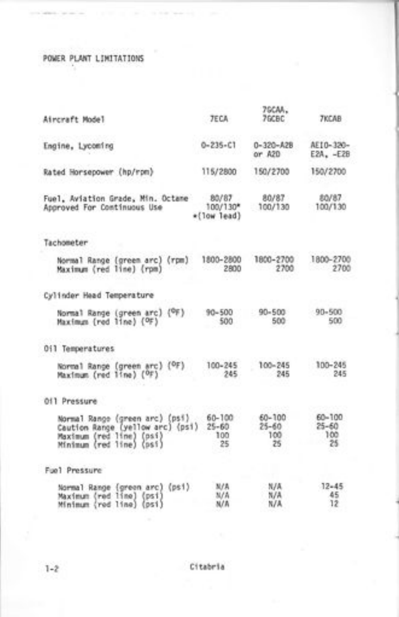
POI,IER PLANT LII4ITATIONS
Ai rcraft liiode 1
7GCM,
TECA TGCBC TKCAB
Engine, Lyconi ng 0-235-Cl 0-320-A2B AEI0-320-
or A2D E?'p., -E?B
Rated Horsepower (hp/rpm) ll5/2800 15012700 150/2700
Fuel, Aviation Grade, I'lin. octane 80/87 80/87 80/87
Approved For contJnuous lJse 100/130* 100/130 100/130
*(lolt, lead)
Tachometer
Normal Ranqe (qreen arc) (rpm) 1800-2800 1800-2700 1800-2700
l,laxinum (red line) (rpn) 2800 2700 2740
Cy]i nder Head Temperature
Nonnal Range lgreen arc) (oF) 90-500 90-500 90-500
l4axinum (red line) (oF) 500 500 500
0il Tenperatures
NorrEl Ranqe (green arc) (oF) 100-245 100-245 100-245
llaxinm (red line) (oF) 245 245 245
0i l Pressure
Normal Ranqe (sreen arc) (ps'i ) 60-100 60-100 60-100
caution Ranqe (vellow arc) (psi) 25-50 25-60 25-60
Maximun (red line) (psi) 100 ]00 ]00
l'linimum (red line) (psi) 25 25 25
Fuel Pressure
Normal Ranse (sreen arc) (psi) N/A N/A 12-45
Max'imum (red line) (psi) N/A N/A 45
l4inimun (red line) (psi) N/A N/A 12
1-2 ci tabri a
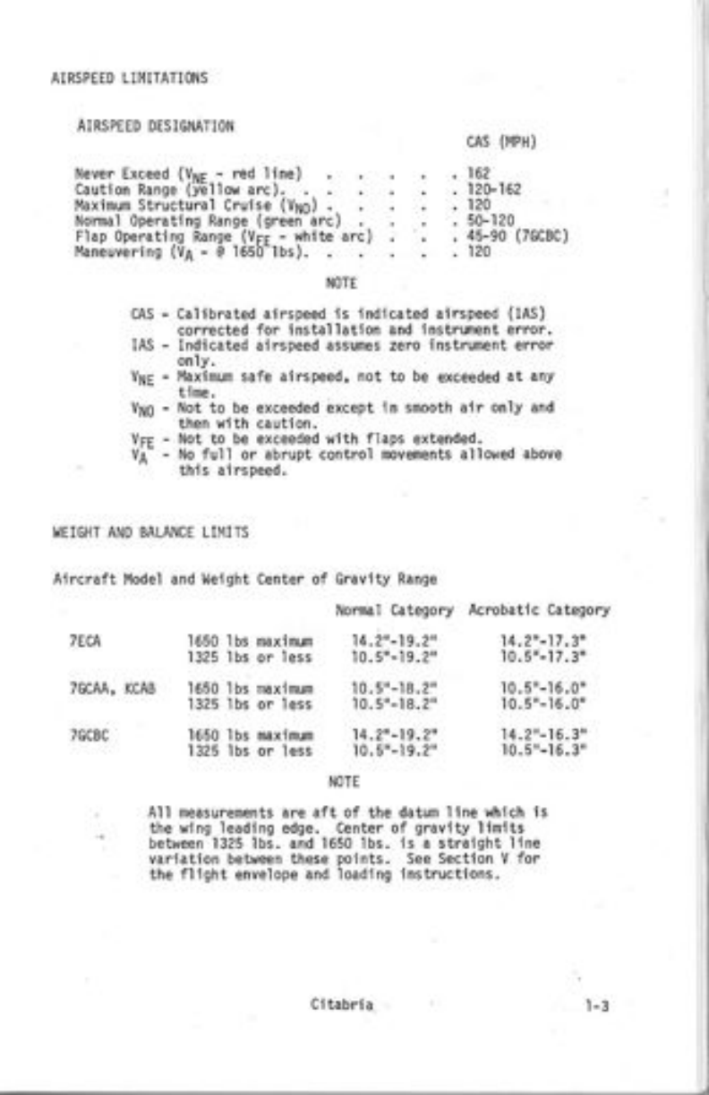
AIRSPEED LiMITATIONS
AIRSPEED DESIGNATION
cAs -
IAS -
Vte -
vNo -
vre -
cAs (r4PH)
,162
. 12V162
. 120
.50-120
. 45-90 (7GCBC)
. 124
Never Exceed fV". - red line)
Cauti on Ranqe '(iEl I ow arc ) . .
l,laximum Structural Crui se (Vx6)
Nonnal operating Range (greeri arc) .
Flap 0perating Range (VFF - white arc)
Maneuvering (vl - @ 1650-lbs).
NOTE
calibrated airspeed is indicated airspeed (IAs)
corrected for installation and instrunent errcr.
Indicated airspeed assumes zero instrument elror
only.
l,4aximum safe airspeed, not to be exceeded at any
time.
Not to be exceeded
then with caution.
Not to be exceeded
No ful l or abrupt
th'is airspeed.
except in smooth air only and
with flaps extended.
control novenents al l owed above
I,IEIGHT AND BALANCE L]MITS
Aircraft Model and l,leight Center of
TECA
7GCAA, KCAB
TGCBC
]550 lbs naximum
1325 lbs or less
1650 lbs naximun
1325 lbs or less
naxinum
or less
Gravity Range
Normal Category
14.z',-1s.2"
't0.5"-19.2'
10.5"-18.2"
10.5"-18.2"
10,5"-19.2"
NOTE
Acrobatic Category
14.2'-17.3',
't0.5"-15.0"
I 0.5'- 16.0'
14.2r-15.3"
10.5"-'t5.3"
1650
1325
lbs
'lbs
A'l'l measurenents are aft of the datum line which is
the l,ling ieading edge. Center of gravity linits
betueen 1325 lbs. and 1650 lbs. is a straight line
variation between these points, See Section V for
the fllght envelope and loading instructions.
Ci tabri a
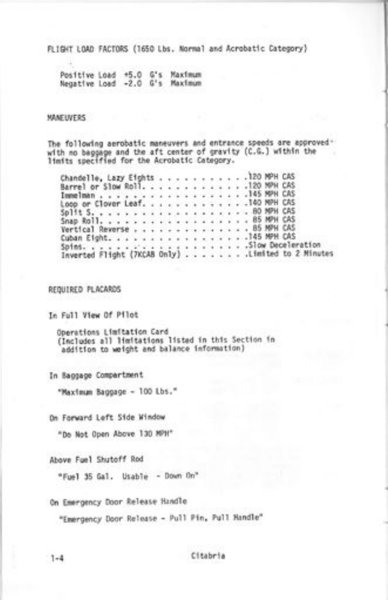
I4ANEUVERS
The folio!,,ing aerobatic maneuvers and entrance -speeds are approved'
wlth no bagg;ge and the aft center of gravitv (C.G.) wlthin the
linlts specified for the Acrobatlc Category.
chandelle, Lazy Eights .izo t'lpH cns
Barrel or SlollJ Ro'll. .120 l4PH CAs
Immelman . .145 llPH CAS
Loop or Clover Leaf. . . , .'140 l4PH CAS
split s. . 80 llPH cAs
Snap Rol l. . 85 I'IPH CAs
Vertical Reverse , 85 I'IPH CAS
Cuban Eight. .145 l'4PH CAs
Spins. , ... .Siow Deceleration
Iilverted Fliqht (7KCAB only) .Limited to 2l'4inutes
FLIGHT LOAD FACToRS (1650 Lbs, Normal and Acrobatic Categorv)
Posltive Load +5,0 G's Maxlnum
Negative Load -2,0 G's l'laxlmum
REqUIRED PLACARDS
In Full View 0f Pl'lot
operati ons Linitation card
(Includes all'linitations listed in thls Sectlon in
'additlon to weight and balance information)
In Baggage Compartrcnt
"l'laxlnun Baggage - 100 Lbs,"
0n Foruard Left Side I'lindow
"Do Not open Above 130 I'IPH"
Above Fuel Shutoff Rod
"Fuel 35 ca1 . Usable - Down 0n"
0n Energency Door Release Handle
"Emergency Door Release - Pull Pin' Pu]1 Handle"
l -4 Ci tabri a
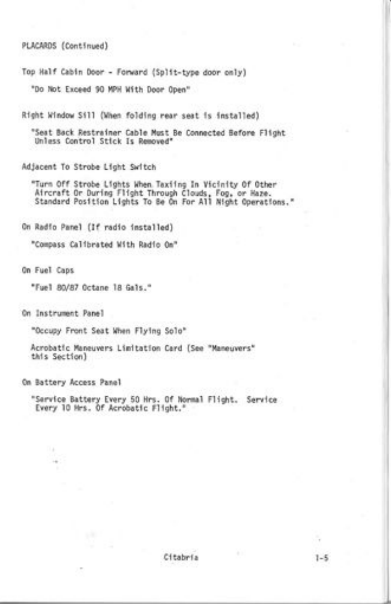
PLACARDS (Continued)
Top Half Cabin Door - Fonrard (Spllt-type door only)
"Do Not Exceed 90 l'1PH l,{ith Door 0pen"
Right llindow 5i1l (When folding rear seat is installed)
"Seat Back Restrainer Cable l,lust Be Connected Before FliSht
Uniess Coniro'l Stick Is Renoved"
Adjacent To Strobe Light Switch
rrTurn off Strobe Lights l.lhen. Tax'iing In Vicinity 0f other
Aircraft 0r During Flight Through Clouds, Fog, or Haze.
Standard PosJtion Lights To Be 0n For All Night operatlons."
0n Radlo Panei (If radio installed)
"Conpass Callbrated l,lith Radio 0n"
0n Fuel caps
"Fuel 80/87 0ctane l8 cals."
0n Instrurnent Panel
"occupy Front Seat l,lhen Fly'ing Solo"
Acrobatic l4aneuvers Limitation Card (see "l4aneuvers"
this Secti on)
0n Battery Access Panel
"Service Battery Every 50 Hrs. 0f Nonnal Flight. Service
Every l0 Hrs. 0f Acrobatlc Flight.'r
i
SECTION II
E}.lERGENCY PROCEDURES
INDEX
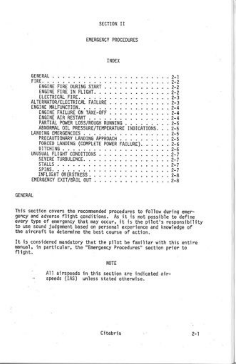
GENERAL. . .2-1
FIRE. . 2-2
ENGINE FIRE DURING START . 2-2
ENGINE FIRE IN FLIGHT. . 2-2
FAILURE
rlri-orr
ELECTRICAL FIRE.
ALTERNATOR/ELECTRI CAL
ENGINE MLFUNCTION.
ENGINE FAILURE ON
ENGINE AIR RESTART . . 2-4
PARTIAL PO}.IER LOSS/ROUGH RUNNING . , 2-5
ABNORMAL OIL PRESSURE/TEI4PERATURE INDICATIONS. . 2.5
LAIiIDI NG EIT1ERGENCIES . . .2-5
PRECAUTIONARY LANDING APPROACH
FORCED LANDING (COI,,IPLETE POWER
t_E
FATLURE). . . 2-6
DITCHING. 'A
UNUSUAL FLIGHT COI.]DITIONS . 2-7
SEVERE TURBULENCE. . .2.7
STALLS . . 2-7
NOTE
All ar'rspeeds in this section are indicated air-
speeds (lAS) unless stated otherr,iise.
SPINS. . . 2-7
INFLIGHT OVERSTRESS. , 2-8
EMERGENCY EXIT/BIIL OUT . . 2-8
GENERAL
Th'is section coyers the recomlended procedurcs to follow durinq ener-
gency and adverse flight conditions, As it is not possible to define
every type of emergency that may occur, it is the pilot,s responsibility
to use sound judgEnent based on personal experience and knor,/ledge of
the aircraft to determine the best course oi action.
It is considered nandatory that the pllot be familiar with this entire
mnual, in particular, the 'rEmergency Procedures', section prior to
fl i ght.
Citabria
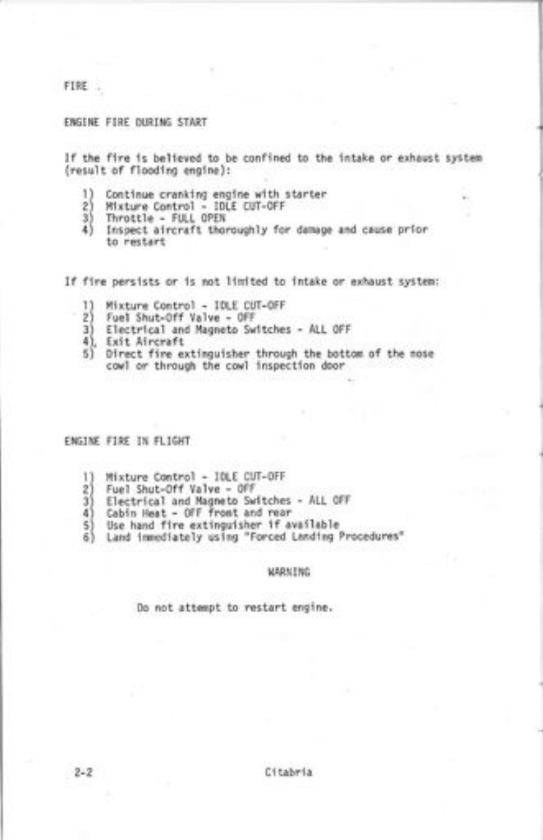
FIRE..
EIIGII'IE FIRE DURING START
If the fire is believed to be confined to the
(resul t of flooding englne):
l) continue cranking engine with starter
2) l',lixture Control - IDLE CUT-oFF
3) Throttie - FULL oPEN
4) Inspect aircraft thoroughly for damage
to restart
I
2
3
4
5
6
i ntake systen
and
If fire persists or is not lirnited to intake or exhaust
l ) l4ixture Control - IDLE CUT-oFF
2) Fuel Shut-0ff Valve - oFF
3) Electrical and I'lagneto Switches - ALL oFF
4), Exit Aircraft
5) Direct fire extinguisher through the bottom of t
cowl or through the cowl inspection door
ENGINE FIRE IN FLIGHT
Mixture Control - IDLE CUT-oFF
Fuel Shut-off Valve - oFF
Electrical and Magneto Swltches - ALL OFF
Cabin Heat - oFF front and rear
Use hand fire extinguisher if availab'le
Land imediately using "Forced Landing Procedures"
I,IARNING
Do not attempt to restart engine.
2-2 Ci tabria
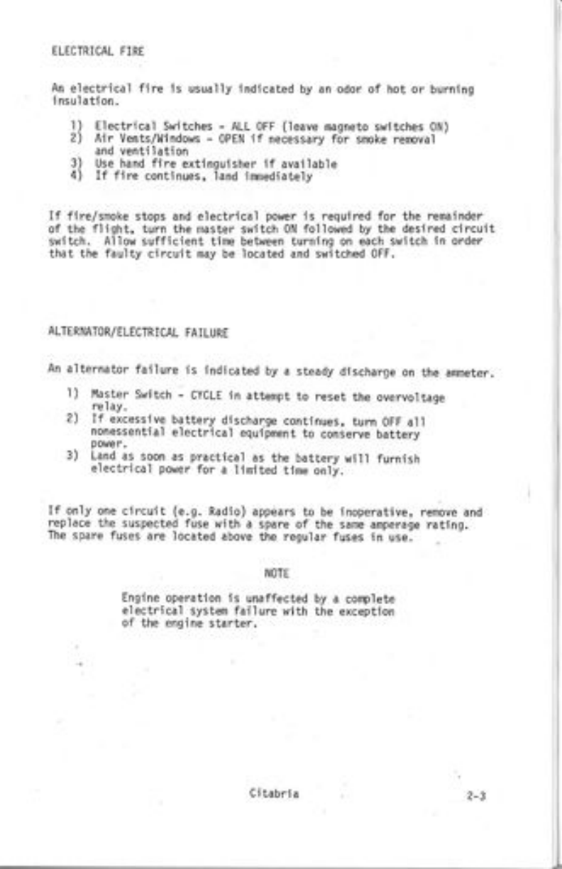
ELECTRICAL FIRE
An electrical fire is usually
i nsul ati on. indicated by an odor of hot or burning
Electrical Switches - ALL oFF (leave nagneto switches 0N)
Air Vents/Windows - 0PEN if necessary for smoke removal
and ventilation
Use hand fire extinguisher if avai lable
If fire continues, land imnediately
If fire/snoke stops and electrical power is required for the remainder
of the flight, turn the master switch 0N followed by the desired circuit
switch. Allow sufficient time between turninq on each switch in order
that the faulty circuit may be located and switched oFF.
r)
2)
3)
4)
ALIERNATOR/ELECTRICAL FAILURE
An alternator failure is indicated by a steady discharge on the ameter.
1) Master Switch - CYCLE in attempt to reset the overvoltage
re I ay.
2) If excessive battery discharge continues, turn OFF all
nonessential electrical equipnent to conserve battery
power,
3) Land as soon as prdctical as the battery will furnish
electrical power for d limi ted time only.
If only one circuit (e.9. Radio) appears to be inoperative, remove and
replace the suspected fuse with a spare of the same amperage rating.
The spare fuses are located above the regular fuses in use-
NOTE
Engine operation is unaffected by a cofiplete
electrical system failure with the exception
of the engine starter.
Citabri a2-3
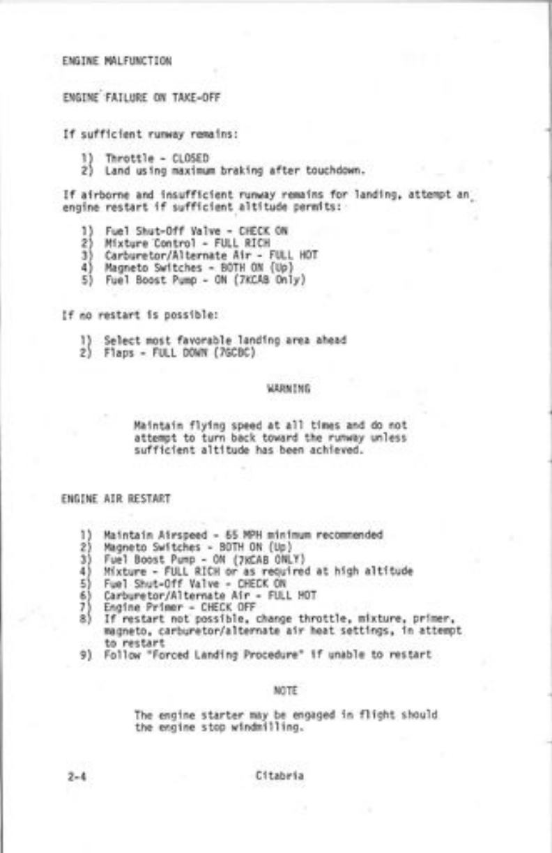
ENGINE MLFUNCTION
ENGINE..FAILURE ON TAKE-OFF
If sufficient runway remains:
l) Throttle - CLoSED
2) Land using maximufl braking after touchdown.
If airborne and insufficient runway remains for landing, atterlpt an
engine restart if sufficlent altitude permlts:
1
2
3
4
Fuel Shut-off Valve - CHECK 0N
Mxture control - FULL RICH
Carburetor/Al ternate Air - FULL HoT
l'lagneto Switches - BoTH 0N (Up)
Fuel Boost Pump - 0N (7KCAB only)
If no restart is possible:
I ) select nost favorable landlng area ahead
2) Ftaps - FULL Dol,tN (7GCBC)
I,IARN ING
llaintain flying speed at al] times and do not
attenpt to turn back toward the runway unless
sufficient a'ltitude has been achieved.
ENGINE AIR RESTART
l
2
3
4
5
6
1
8
l4aintain Airspeed - 65 MPH minlmum recomnended
l,laqneto Switches - 80TH 0N (Up)
Fuel Boost Pump - 0N (7KCAB oNLY)
l4ixture - FULL RICH oi as required at high altitude
Fuel Shut-off Valve - CHECK 0N
Ca rbure tor/Al ternate Air - FULL HoT
Engine Primer - CHECK oFF
If restart not possible, change throttle, nixture, primer,
nagneto, carburetor/alternate air heat settings, in attenpt
to restart
9) Follow "Forced Landing Procedure" if unabie to restart
NOTE
engine starter may be engaged in flight should
engi ne stop windmilling.
The
the
2-4 CJtabria
PARTIAL POl,lER LOSS/ROUGH RUNNING
1) Follow the engine air restart procedures
2) Land as soon as practical using ',precautionary Landlng
Approach" procedures
Carburetor icing is indicated if a gradual RpM]oss is noticed. The
carburetor/a l terna te air should be FULL HOT as long as suspected icing
condi tions exist.
ABNORI'AL OIL PRE5SURE/TEI4PERATURE INDICATIONS
0il pressure and temperature problens are usually related with one
affecting the other. Before any drastic actJon is taken, cross check
other engine instrurnents and control settings in an attenpt to deter-
nine the source of the problen.
High oil tenperature is general]y a result of loss of oil, overheating
(note CHT if available) or a malfunctioning oil cooler by-pass valve.
If the situation renains unchecked, oil pressure usual ly drops resulting
in possible engine damage. Power should be reduced whi'le naintainJng
crulse airspeed; place mixture in FULL RICH position and land as soon
as practical.
Little or no oil pressure js usually caused by a faiied pressure relief
valve, pump, loss of oi1, clogged oil line, high oil temperature or a
defective gauge. A landing should be made as soon as practlcdl using
ninimun RPl,l changes. Plan a "Precautionary Landing Approach" as com-
p'lete engine faj lure is possible at any tine.
LANDING EMERGENCIES
PRECAUTIONARY LANDING APPROACH
A precautlonary landlng approach should be used whenever power is still
available but a complete power failure is considered imj;ent. Maintain
a.higher and closer pattern than nomal in dttempt to renain in qliding
distance of the intended touchdown point. tJse tire normal landini
procedures in addition:
l) Airspeed - 65 t4PH reconnended (60 t4pll nininurn)
2) Throttle - CL0SED when in gl iding distance of runway
3) Flaps - LOllER AS NEEDED in'increise approach desceni
, angte (7ccBc)
NOTE
Slipping the aircraft by cross controllinq the
ludder and ailerons will increase the rate of
descent both with or without flaps. If a cross-
t/ind exJsts, place the lower i{ing into the wind,
j
Ci tabria 2-5
F0RCED LANDING (Complete Power Failure)
If the engine cannot be restarted in flight, tnin the aircraft to the
reconnended glide speed. Remain within gliding distance of the intended
point of landing. l,laintain a higher and closer pattern than normal
na ki ng allowance for wind.
Additional altitude can be lost by extending flaps or slippjng the air-
craft. Diving the aircraft in an attenpt to lose altitude when flying
into a headwind ui ll only increase the required landing distance.
'l
2
3
4
5
6
7
Airspeed - Maintain 60-65 IYPH
lvlixture - IDLE CUT-oFF
Fuel Shut-off Valve - oFF
llaster Switch - 0N
Flaps - UP to increase glide range (7GCBC)
Radio - MAYDAY 121.5 MHz
Attempt to position the aircraft approximately 1000 feet above
qround level (AGL) over the intended point of landing or 500
feet when downwind and abeam the intended point of landing.
8) Electrical Switches - ALL oFF
9) 0n Final Approach
a) Airspeed - 65 l4PH (60 MPH minimum)
b) Flaps - Dolll,l after intended point of landing
assured (7GCBC)
lo) Touchdown r4ith minimum airspeed (three point full stall ) if
I andi ng on rough terrajn.
NOTE
If necessary, after aircraft has come to a conplete
stop, renove and activate the emergency locator
transnitter from the aircraft for increased trans-
ni t ti nrt range.
DITCHI NG
Should it become necessary to nake a forced landing over water, follow
the "Forced Landinq Procedures" in addition to the follo\,]ing:
Cabin Side Door - JETTISoN
Land into wind if high winds are evident or paral]el to swells
wi th calm wihds
Flaps - UP (allows higher nose attitude at tbuchdown)
contact the water with nose high attitude
D0 NoT STALL prior to touchdown
After cominq to conplete stop - EXIT AIRCRAFT
1)
2)
3)
4)
5)
6)
NOTE
A'ircraft cannot be depended
tati on after contacting the
on to provi de floa-
watef-
2-6 Ci tabri a
UNUSUAL FLIGHT CONDITIONS
SEVERE TURBULENCE
To prevent.overstressing the aircraft do not exceed IZO MpH in rough
air. To ninimize personal discomfort, decrease the IAS below 80 MFH.
l"laintain a level flight attitude rather than fiying by reference to
the altimeter and ajrspeed indicator as the pit;t-;taiic insiiuments
may becone very erratic,
5TALL5
The Citabria stall characteristics are conventional. The stal.l warning
horn, if instalied, uiil proceed the actual stall by 5-10 t4pH dependini
on the.amount of power used. There is sufficient aerodynamic buifetini
preceeding the stail to provide the piiot with an adequite varning.
Aileron.control response in a fuily stalled condition is narginal.
Large aileron deflections will aggiavate a near stalled condition and
their use is not recormended to iiintain taterai ionirot. -if," -"rOae"
is very effective and shouid be used for naintaining laterai conirol
in a stal led condition with the ailerons placed in i nerirai posi on.
To recover from a stail, proceed as follows:
i) Nose Attitude - LoliER with fon/ard movenent of control stick
2) Throttle - FULL oPEN simuitaneousiy with control stick movenent
3) Use rudder to maintain lateral control
SPINS
If a spin is inadvertently entered, imnediate recoverv should be
initiated. The recovery procedure ls as follows:
l) Throttl e - CLoSED
2) Rudder - FULL DEFLECTIoN opposjte d.irection of rotation
3) Etevator - SLIGHTLY F0Rl,tARb 0F NEUTRAL
4) Aiierons - NEUTRAL P0SITI0N
llhen rotation stops (l/2 - I turn after recovery initiated)
5) 'Rudder - NEUTRALIzE
6) Nose Attitude - RAISE smooth'ty to levet flJght attitude
hIARNI NG
During the spin recovery, the airspeed will build
very rapidly with a nose lolr attitude. Do not use
full or abrupt elevator control movements,
Citabria
Should an overstress occur due to exceeding the alrspeed or load factor
linits, aerobatics should be tenninated imediately, Fly at a reduced
airspeed, (60 - 70 PH) to a suitable tanding poini. D0 NOT under any
circunstances, nake large control moverents or subjdct the aircraft to
additional G loadlngs above that required for straJght and level fllght.
Aft€r ianding, the aircraft should be inspected by ; mechanic prJor to
INFLIGHT WERSIRESS
the next fIight,
EMERGENCY EXIT/BATL OUI
l)
2)
3)
4)
Throttle - CL0SED
Door - JETTISo using Emergency Jettison Handle
Use the cabin door frane for support. DJve straight
out and slightly aft of wing struts.
Parachute - oPEN imediately when clear of aircraft
I{OTE
Energency ground exit is also possible through
the left ulndou.
2-8 Ci tabria
SECTION IIi
I'IORMAL OPEMTING PROCEIruRES
INDEX
GENERAL. . .,.3-l
PREFTIGHT Ii{SPECTION. . .3-2
BEFORE SIARTING . .3.3
STARTING, ...3.4
STARTING (7KCAB ONLY) . . . .3-4
TAXI. . 3-5
BEFORE TAKE-OFF j.3-6
TAKE-oFF (Nomal) . .3-6
TAKE-oFF (obstacle)..... ... .3-7
TAKE-oFF (Soft Flel.d) . . ,3-7
cLIlrtB . ...T7
CRUISE. , 3-8
.AEROBATICS. 3-8
DESCENT . . 3-9
LAi,IDING (l{ormal ). . 3-9
LANDING (obstacle) , 3- t0
sHUTDolrN. . 3- 10
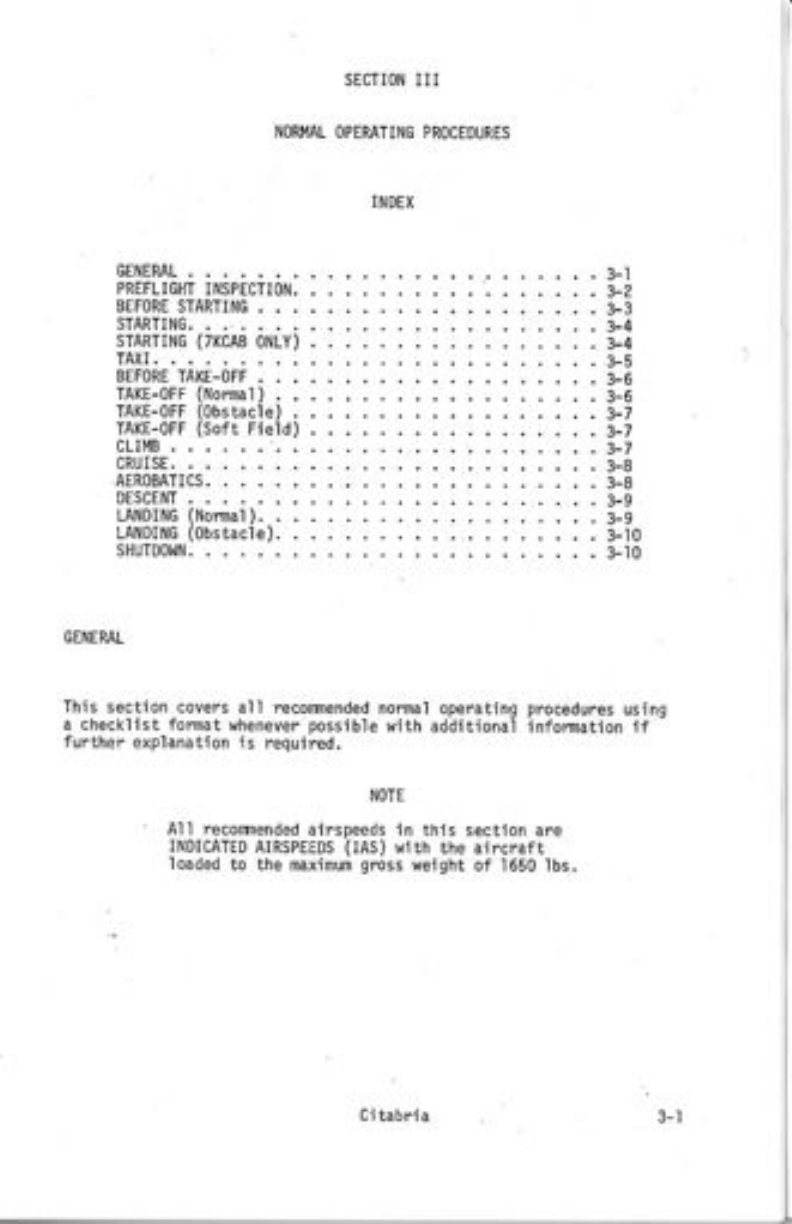
GENEML
This section covers all reconnended normal operating procedures using
a checklist format wheneverrposslble with additional infonDation if
further explanation is requi red.
NOTE
All recontnended airspeeds in thls section are
INDICATED AIRSPEEDS (IAS) wtth the aircraft
loaded to the maxinun grcss weight of 1650 lbs.
Ci tabria
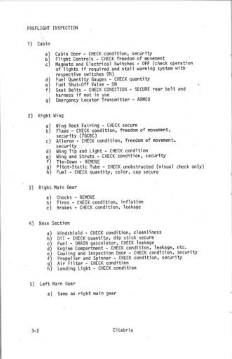
1) Cabin
a) Cabin Door - CHECK condition' security
bi Flioht Controls - CHECK freedorn of novenent
ci Maoieto and Electrical switches - oFF (check operation
' of-lights if required and stall warning systen with
respecti ve switches 0N)
d) Fuei Quantity Gauges - CHECK quantity
e) Fuel shut-off valve - 0N
f) Seat Belts - CHECK C0NDITIoN - SECURE rear belt and
harness if not in use
g) Emergency Locator Trdnsmitter - ARMED
PREFLIGHT INSPECTION
2) Risht l,li ng
a)
b)
c)
Ninq Root Fairinq - CHECK secure
Flais - CHECK conditlon, freedon of movement'
security (7GCBC)
Aileron - CHECK condition, freedom of movenent'
securi tv
Llino Tii and Liqht - CHECK condition
tlini ani struts-- cHEcK condition, securlty
Tie-Down - REM0VE
Pitot-Static Tube - CHECK unobstructed (visual check only)
Fuel - CHECK quantity, color, cap secure
d)
e)
f)
s)
h)
3) Rjght l'lai n Gear
4) Nose
5) Left Ma in Gear
a) Same as righf nain gear
chocks - RE oVE
Tires - CHECK condition, inflation
Brakes - CHECK condition' leakage
Section
llindshield - CHECK condition' cleanliness
Oil - CHECK quantitv, dip stjck secure
Fuel - DRAIN qascolator, CHECK leakage
Fnoine comDarinent - CHECK condition' leakage, etc.
coilinq ani lnspection Door - cHEcK condition, security
Propeller and Spinner - CHECK condition' security
Air Fitter - CHECK conditioh
Landing Light - CHECK condition
a)
b)
c)
a)
b)
c)
d)
e)
f)
s)
h)
Citabria
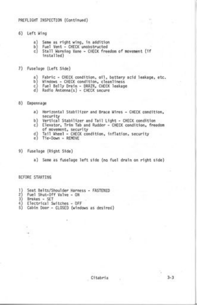
PREFLIGHT INSPECTIoN (Continued)
6) Left
of novelEnt (rt
l.{i ng
Sane as right wing, in addition
Fuel Vent - CHECK unobstructed
Stall ldarnlng Vane - CHECK freedon
lnstalled)
a)
b)
c)
7)
8)
Fuselage (Left Side)
a) Fabric - CHECK condition, oi1, battery acid leakage, etc.
b) Ulindows - CHECK condition, cleanlJness
c) Fue'i Belly Drain - DRAIN, CHECK leakage
d) Radio Antenna(s) - CHECK secure
Enpennag€
a) Horizontal Stabilizer and Brace t,lires - CHECK condition,
security
b) Vertical Stabilizer and Tail Light : CHECK condition
c) Elevator, Trim Tab and Rudder - CHECK condition, freedom
of novenent, security
d) Tail Wheel - CHECK condition, inflation, security
e) Tie-Down - REMoVE
Fuse lage (Right Side)
a) Same as fuselage left side (no fuel drain on right side)
e)
r)
2\
3)
4)
5)
BEFORE STARTING
Seat Belts/Shoulder Harness - FASTENED
Fuel Shut-off Va'lve - 0N
Brakes - SET
Electrica'l Switches - oFF
Cabin Door - CLoSED (uindows as desired)
Citabri a
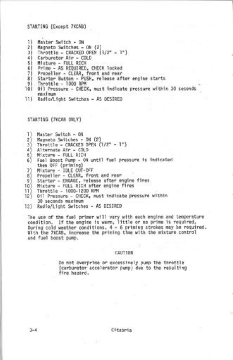
STARTING (Except TKCAB)
Maiter switch - 0N
Magneto switches - 0N (2)
Throttle .- CRACKED oPEN (1/2" - 'l^\
Carburetor Air - CoLD
Mixture - FULL RICII
Prime - As REqUIRED, CHECK locked
Propeller - CLEAR, front and rear
Starter Button - PUSH, release after enqine starts
Throttle - 1000 RPI'I
0il Pressure - CHECK, nust indicate pressure within 30 seconds
1
2
3
4
5
6
7
9
'10
'l
2
3
4
5
6
7
I
9
l0
lt
12
na xi mum
ll ) Radio/Light Switches - AS DESIRED
STARTING (7KCAB ONLY)
Master switch - 0N
Masneto Switches - 0N (2)
Thiotfle - cMcKED oPEN (l/2" - l')
Alternate Alr - CoLD
l,4ixture - FULL RICH
Fuel Boost Pump - 0N until fuel pressure is indicated
then oFF (priming)
l4ixture - IDLE CUT-oFF
Propeller - CLEAR, front and rear
Starter - ENGAGE, release after engine fires
I'lixture - FULL RICH after engine fires
Throttle - 1000- 1200 RPM
0il Pressure - CHECK, must indicate pressure within
30 seconds maxlmum
l3) Radio/Light Switches - AS DESIRED
The use of the fuel priner will vary with each engine and temperature
condition. If the engine is wdrm, 'little or no prime is required.
During cold weather conditions, 4 - 5 priming strokes nay be required.
l,lith the 7KCAB, increase the prining time with the mixture control
and fuel boost pump.
CAUTION
Do not overprime or excessively pump the throttle
(carburetor accelerator pump) due to the resulting
fire hazard.
3-4 Ci tabria
Other manuals for CITABRIA 7ECA
1
This manual suits for next models
3
Other Bellanca Aircraft manuals


