moyes Litespeed RX 3 User manual

Moyes Delta Gliders Pty. Ltd.
Version 2
LITESPEED RX
owners manual


LITESPEED RX OWNERS MANUAL
Version 2 1
CONTENTS
Contents................................................................................................ 1!
Amendments......................................................................................... 2!
Introduction ........................................................................................... 3!
Description of Design............................................................................ 4!
Specifications........................................................................................ 5!
Operating Limitations ............................................................................ 6!
Disclaimer ............................................................................................. 7!
Getting Started...................................................................................... 8!
Assembly Procedures ......................................................................... 12!
Pre-Flight Check ................................................................................. 17!
De-Rigging the Litespeed RX ............................................................. 19!
Flying the Moyes Litespeed RX .......................................................... 23!
Tuning Hints........................................................................................ 27!
Performance Tuning ........................................................................... 29!
Glider Care.......................................................................................... 31!
Maintenance Schedule ....................................................................... 33!
Sail Removal....................................................................................... 34!
Checking The Litespeed RX Stability System..................................... 35!
Purchase Record ................................................................................ 38!
AN Bolt IndeX ..................................................................................... 39!
Maintenance Log ................................................................................ 39!

LITESPEED RX OWNERS MANUAL
2Version 2
AMENDMENTS
Version
Date
Changes
1.00
18/10/12
•Created original owners manual
•
2
17/2/15
•Combined RX3, RX3.5, RX4 and RX5 into one manual
•

LITESPEED RX OWNERS MANUAL
Version 2 3
Moyes Delta Gliders Pty. Ltd.
INTRODUCTION
Thank you for choosing the Moyes Litespeed RX. You have chosen wisely.
The Litespeed RX incorporates the latest high performance hang gliding
design technology.
Since 1967, Moyes Delta Gliders has strived to be on the cutting edge of
developing hang gliders of the highest calibre. We aim to provide a
comprehensive international network to service all pilots. We work with some
of the best pilots and designers in the world to ensure that our gliders have
the best possible performance, handling and safety.
We wish you the very best flying,
The Moyes Team

LITESPEED RX OWNERS MANUAL
4Version 2
DESCRIPTION OF DESIGN
The latest evolution and third generation of the innovative Moyes Litespeed range is the Moyes Litespeed RX.
This glider has been specifically designed for racing and offers a larger wing span and higher aspect ratio
providing enhanced glide and climb characteristics. Despite the larger span and aspect ratio, the Moyes
Litespeed RX handles extremely well due to the advanced sail design and it makes launching, landing and
climbing pleasurable tasks.
The sail top surface is fully constructed from durable PX Mylar cloth and is standard as a full white surface with
Titanium Oxide finish reducing UV effects on the sail. An optional “Technora” sail is also available. The
Technora inlaid sail uses a lighter semi-transparent dark Mylar cloth in the centre of the wing surrounded by
white PX Mylar., the smoke inlaid sail reduces the weight of the sail by approximately 1.5kgs an is
aesthetically pleasing. The under surface is made from Dacron, and is divided into three areas which can be
customised to suit the colour requirements of the pilot.
The Moyes Litespeed RX is supplied standard with full aluminium leading edges, carbon fibre cross bars,
standard aerofoil uprights and a round base bar. The glider flies very nicely in this configuration, however
glider weight can be reduced and handling improved through the inclusion of an extensive range of
performance options.
If using the standard uprights, an aluminium aerodynamic FAST base bar can be added. The preferred option
is to upgrade the A-frame to the Moyes Zoom uprights and carbon fibre speed bar. The Moyes Zoom uprights
have a very low drag coefficient. They are made from extruded aluminium with an electrically etched black
finish. The Moyes Zoom carbon fibre speed bar uses the same aerodynamic profile as the Zoom uprights. The
base bar is hand laid using pre-impregnated carbon fibre cloth and is pressure cured at high temperature to
ensure an attractive and durable finish.
A range of carbon fibre performance options are available when ordering the Moyes Litespeed RX. These
include carbon fibre outer leading edges, carbon fibre inner leading edges, carbon fibre dive sticks, carbon
batten set and carbon fibre leading edge inserts. Except for the carbon batten set, all these options are hand
laid using pre-impregnated carbon fibre and pressure/temperature cured to provide light yet strong
components. The carbon fibre options provide a stiffer and lighter alternative to the standard aluminium
components, contributing to the handling and performance of the glider.

LITESPEED RX OWNERS MANUAL
Version 2 5
SPECIFICATIONS
Model Size
Litespeed RX 3
Litespeed RX 3.5
Litespeed RX 4
Litespeed RX 5
Area (between tight
and loose VG)
12.8 sq.m
13.5 sq.m
13.9 sq.m
14.8sq.m
138 sq.ft.
145 sq.ft.
150 sq.ft.
159 sq.ft.
Span (tight)
9.77 m
10.07 m
10.27 m
10.4 m
32.1 ft.
33.0 ft.
33.7 ft.
34.1 ft.
Nose angle (tight-
loose)
130-125 deg.
130-125 deg.
130-125 deg.
130-125 deg.
Aspect Ratio
7.4
7.5
7.6
7.3
Weight (carb - alu)
31-33 kgs
32-34 kgs
33-35 kgs
34.5-36.5 kgs
68-72 lbs
71-75 lbs
73-77 lbs
76-80 lbs
Optimal pilot weight
63 kgs
73 kgs
83 kgs
93 kgs
139 lbs
161 lbs
183 lbs
205 lbs
Hook-in weight
59-89 kgs
68-108 kgs
75-115 kgs
85-119 kgs
130-196 lbs
150-238 lbs
165-254 lbs
187-262lbs
Packed length
4900 mm
5120 mm
5220 mm
5320 mm
16.07 ft.
16.79 ft.
17.12 ft.
17.45ft.
Short packed length
4020 mm
4240 mm
4340 mm
4500 mm
13.18 ft.
13.91 ft.
14.23 ft.
14.8ft.
C of G front of keel
1343 mm
1343 mm
1353 mm
1343 mm
52.9 inches
52.9 inches
53.3 inches
52.9 inches
Number of battens:
Mainsail
21
23
23
23
Undersurface
6
6
6
6
VNE (truck test)
100 kph
100 kph
100 kph
100 kph
62 mph
62 mph
62 mph
62 mph
VA
74 kph
74 kph
74 kph
74 kph
46 mph
46 mph
46 mph
46 mph
Trim speed
35 kph
37 kph
37 kph
35 kph
22 mph
23 mph
23 mph
22 mph
Stall speed
27 kph
28 kph
29 kph
28 kph
17 mph
17 mph
18 mph
17 mph
Max speed
+120kph
+130 kph
+130 kph
+120 kph
+75 mph
+81 mph
+81mph
+75mph
Best glide speed
47 kph
48 kph
48 kph
47 kph
29 mph
30 mph
30 mph
29 mph
Best glide angle
14.5/1
15/1
15/1
15/1
Glide angle 10:1
70 kph
77 kph
77 kph
75 kph
44 mph
48 mph
48 mph
46 mph

LITESPEED RX OWNERS MANUAL
6Version 2
OPERATING LIMITATIONS
Your Moyes Litespeed RX is a sophisticated, state of the art high performance hang
glider. If maintained correctly it will give you years of safe enjoyable soaring. It is
important that you display a healthy respect for all aspects of aviation and that you
especially understand the increased risks of flying in dangerous conditions or in a
manner that exceeds the glider’s operating limitations.
•Flight operation should be limited to non-aerobatic manoeuvres where the pitch
angle doesn’t exceed 30 degrees up and down to the horizon and bank angles don’t
exceed 60 degrees
•The Moyes Litespeed RX has been designed for foot launched soaring flight and
should not be flown by more than one person at a time
•It should not be flown backwards or inverted
•The recommended minimum pilot skill level is Advanced (Hang 4)
•The Moyes Litespeed RX should not be flown with auxiliary power
•The Moyes Litespeed RX should not be flown in excess of the placard VNE or VA
•VNE (speed never to exceed): 53 mph / 84.8 kph
•VA (maximum rough air manoeuvring speed): 46 mph / 73.6 kph
•Stall speed with maximum pilot weight: Less than 21 mph / 34 kph
•Maximum speed with minimum pilot weight: Less than 77 mph / 124 kph
The Moyes Litespeed RX will resist spinning and will recover quickly if control pressures
are relaxed. Recovery from a stalled turn can be achieved without extreme height loss or
without extreme attitude change if the angle of attack is reduced. Recovery from an
incipient spin will be achieved within half a turn if the angle of attack is lowered to a
normal flying angle.
The Moyes Litespeed RX is capable of flying at speeds greater than the VA and VNE.
We recommend you use an accurate airspeed indicator and familiarise yourself with
control bar positions at these speeds and normal flying speeds.

LITESPEED RX OWNERS MANUAL
Version 2 7
DISCLAIMER
The owner and operator must understand that due to the inherent risk involved in flying
such a unique vehicle, no warranty is made or implied of any kind against accidents,
bodily injury or death. Operations such as aerobatic manoeuvres or erratic pilot
technique may ultimately produce equipment failure, and are specifically excluded from
the warranty.
This glider is not covered by product liability insurance, nor has it been designed,
manufactured or tested to any state or federal government airworthiness standards
or regulations.

LITESPEED RX OWNERS MANUAL
8Version 2
GETTING STARTED
Your new Moyes Litespeed RX may have been shipped to you in the 4.5 metre
breakdown form. If so, you can assemble your glider to its full length by following the
assembly procedures. All references to ‘top’ & ‘bottom’ and ‘left’ and ‘right’ are referred
to with the glider in flying mode.
Please check your packing list.
•Glider
•2 x Back section leading edges: note that the back sections are different between
left and right
•1 x Batten Set: Right=Green/Left=Red/Blue=Undersurface
•1 x Speed Bar
•2 x Tip Bags
•3 x Padding Pieces: A-Frame top & bottom, Keel sleeve
•1 x Batten Pattern
•1 x Snack Pack with owner’s manual and Batten Profile
Assembly from 4.5m Breakdown Form
1. Open the glider bag and roll the glider onto its undersurface.
Undo the straps and extend the sail.
Picture 1
Lay the glider on
Its undersurface
and unfold the sail.
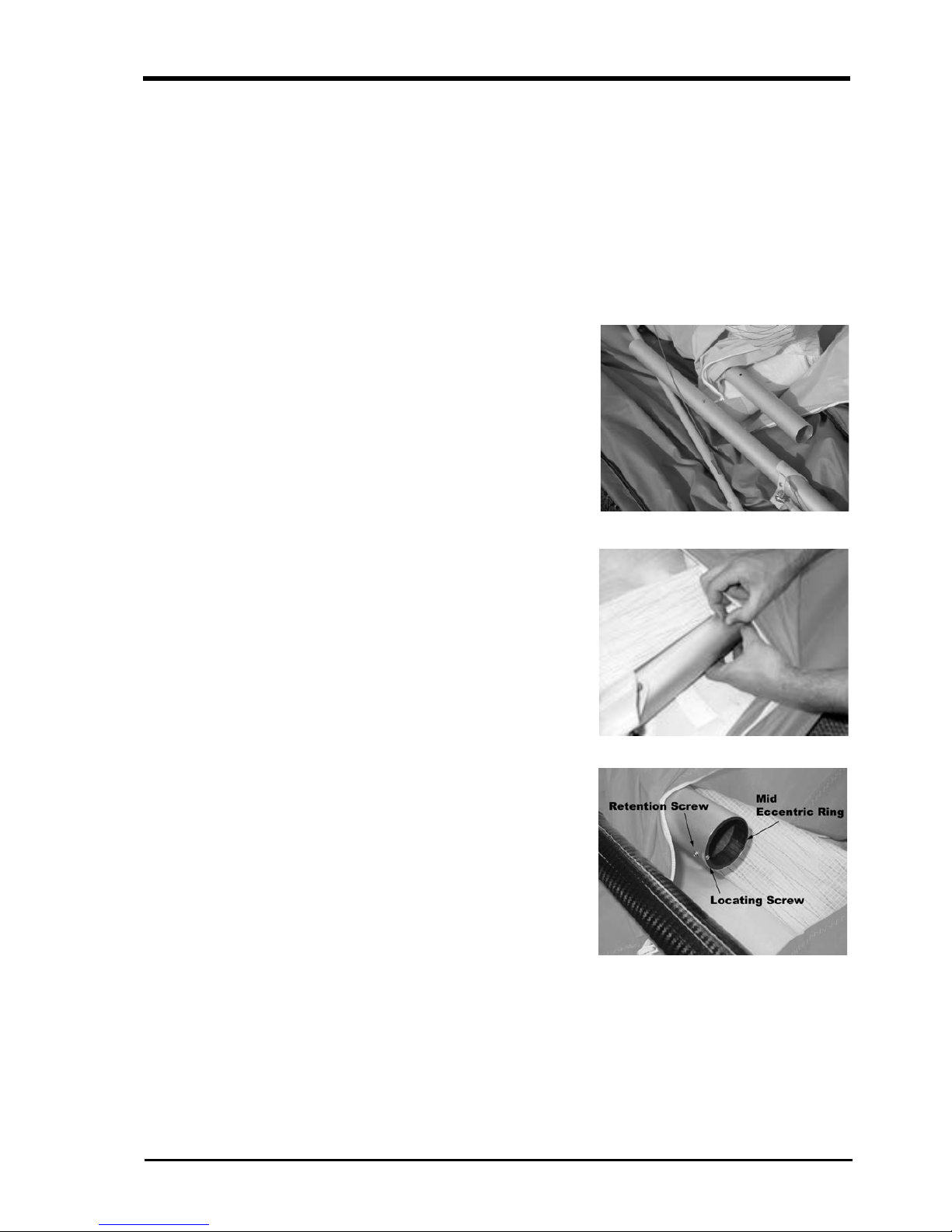
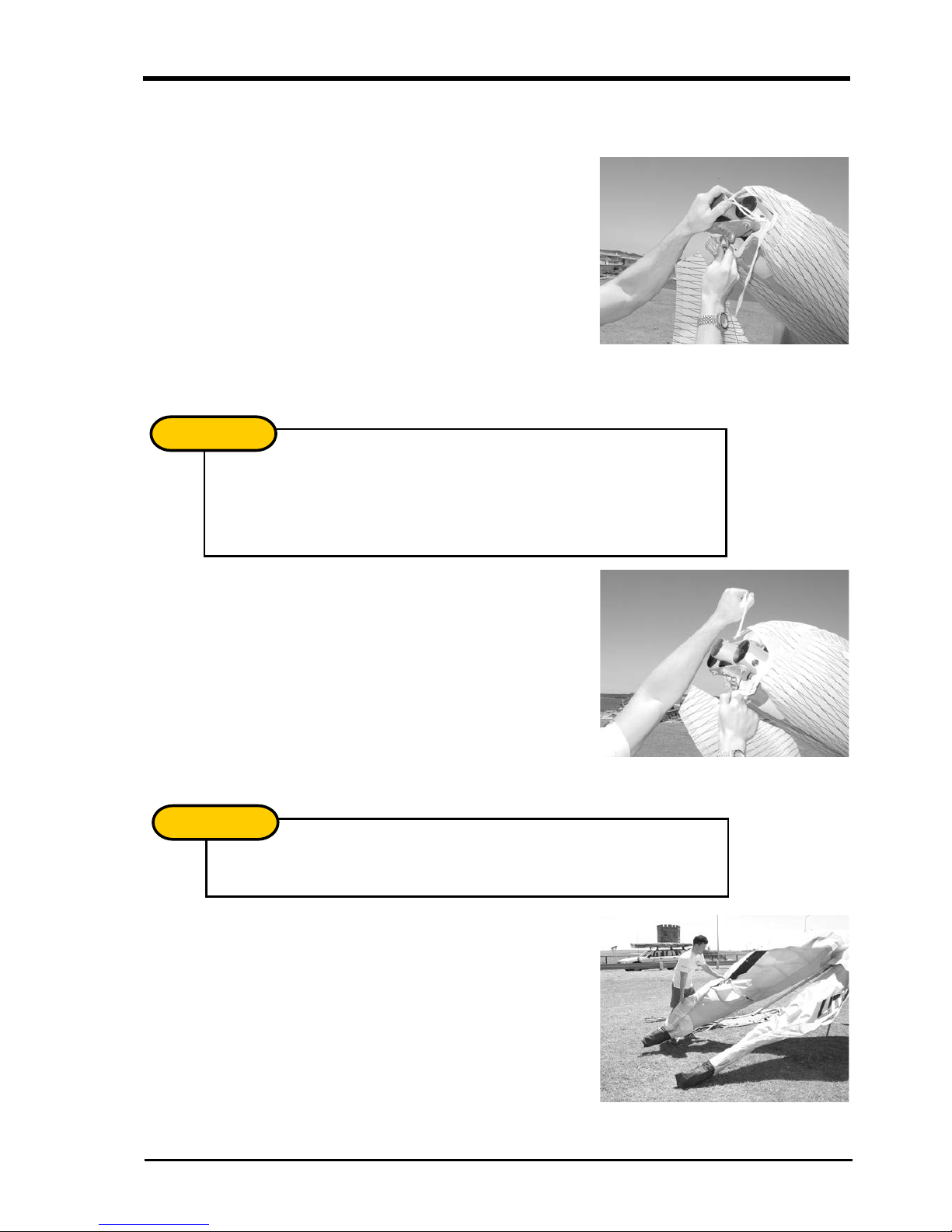
2. Expose the leading edge/cross bar junction through the inspection zip. Remove the
bubble wrap and tape from the leading edge/cross bar junction and the end of the
middle sleeve.
Picture 2
Remove packing materials from leading edge end.
LITESPEED RX OWNERS MANUAL
Version 2 9
3. Aluminium Rear Leading Edge
Insert the right hand back section of leading edge. The right hand back section
differs from the left in the mounting of the outer sprog. You can check this by
picturing that the cable must be on the top side of the leading edge and the sprog
must fold inboard. Push the back section into the mid sleeve while depressing the
push button pin. Continue to push the back section in until it reaches its stop, then
rotate the back section until the mid sleeve location holes align with the push
button pin. Closely check that the push button pin has fully released and that the
back section is secure against rotation forces.
Picture 3
Insert the back
ends of the
leading edge.
Carbon Rear Leading Edge
a. Remove the clevis pin and safety ring from the front
leading edge via the inboard dive stick zipper on the
under surface of the right wing.
b. Access the back end of the aluminium leading edge via
the outboard dive stick zipper. Note the position of the
mid eccentric ring locating screw, as the eccentric ring
must be refitted to the exact same position. Remove
the retention screw and the mid eccentric ring from the
leading edge.
c. Select the right carbon rear leading edge (RLE). This can be done by
extending the dive strut. The dive strut wire must be on the top of the leading
edge to support the dive stick.
d. Fit the mid eccentric ring over the carbon rear leading edge.
LITESPEED RX OWNERS MANUAL
10 Version 2
e. With the outer dive stick folded
towards the nose of the glider,
slide the carbon rear leading edge
into the sail via the glass tip
pocket, allowing the outer dive
stick to exit the sail at the
undersurface zipper. Insert the
carbon rear leading edge into the
front leading edge.
f. Refit the clevis pin and safety pin, ensuring the pin goes through the holes at
the end of the carbon rear leading edge.
g. Slide the mid eccentric ring into the end of the front leading edge, ensuring its
location is the same as when it was removed. Insert the retention screw.
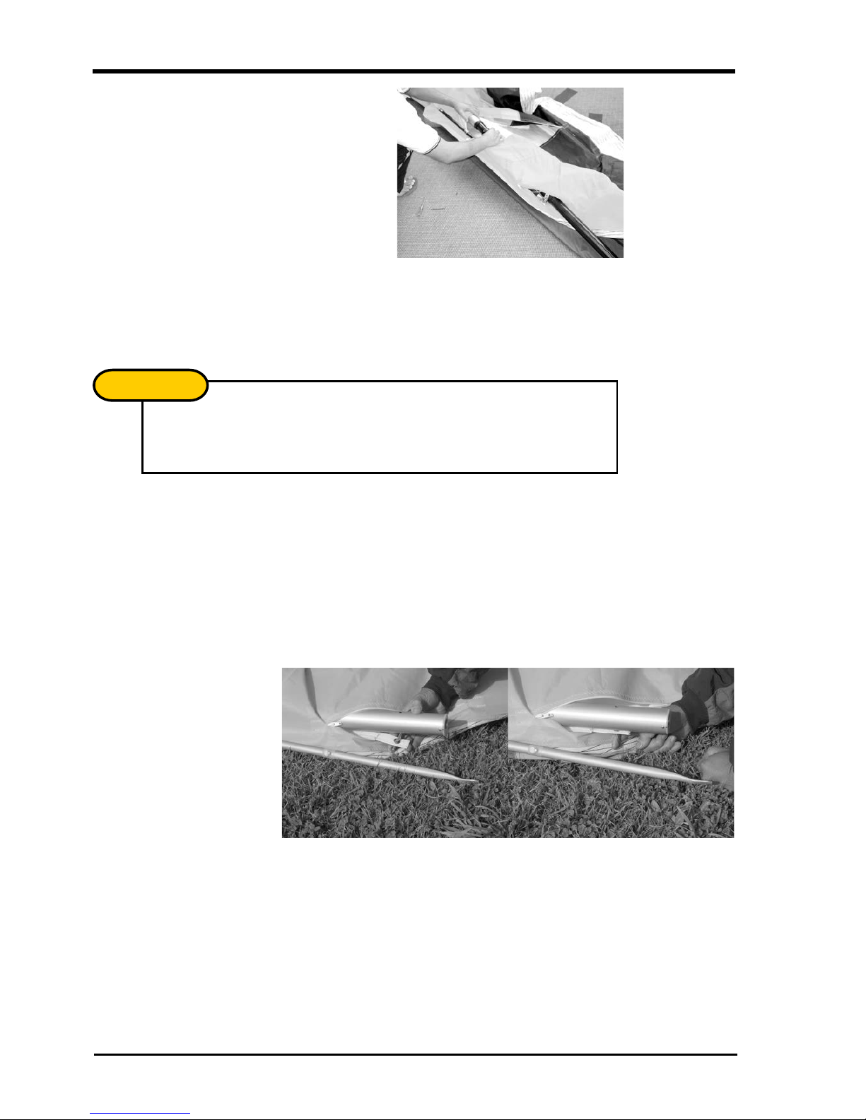
4. Secure the sail by attaching to the tip webbing using the clevis pin and ring supplied.
Insert the pin through the webbing and into the bottom hole at an angle. Straighten
the clevis pin while sliding the webbing towards the leading edge as shown in
Picture 4. Ensure the tip webbing is not twisted and is on the bottom of the leading
edge.
Picture 4
Insert sail pin into end of leading edge.
5. Repeat steps 1-4 to install the left hand back section of leading edge.
Your Litespeed will now be ready for the standard assembly. Before flight, make
a thorough inspection of all tubing and nuts and bolts to ensure no damage has
occurred during transportation (refer to section on pre-flight check).
The rear leading edges are marked “RLE”. This is an abbreviation of “Rear
Leading Edge”, not right leading edge. The left and right side RLE’s must be
identified by ensuring dive strut wire is on top of the leading edge.
NOTE
!
LITESPEED RX OWNERS MANUAL
Version 2 11
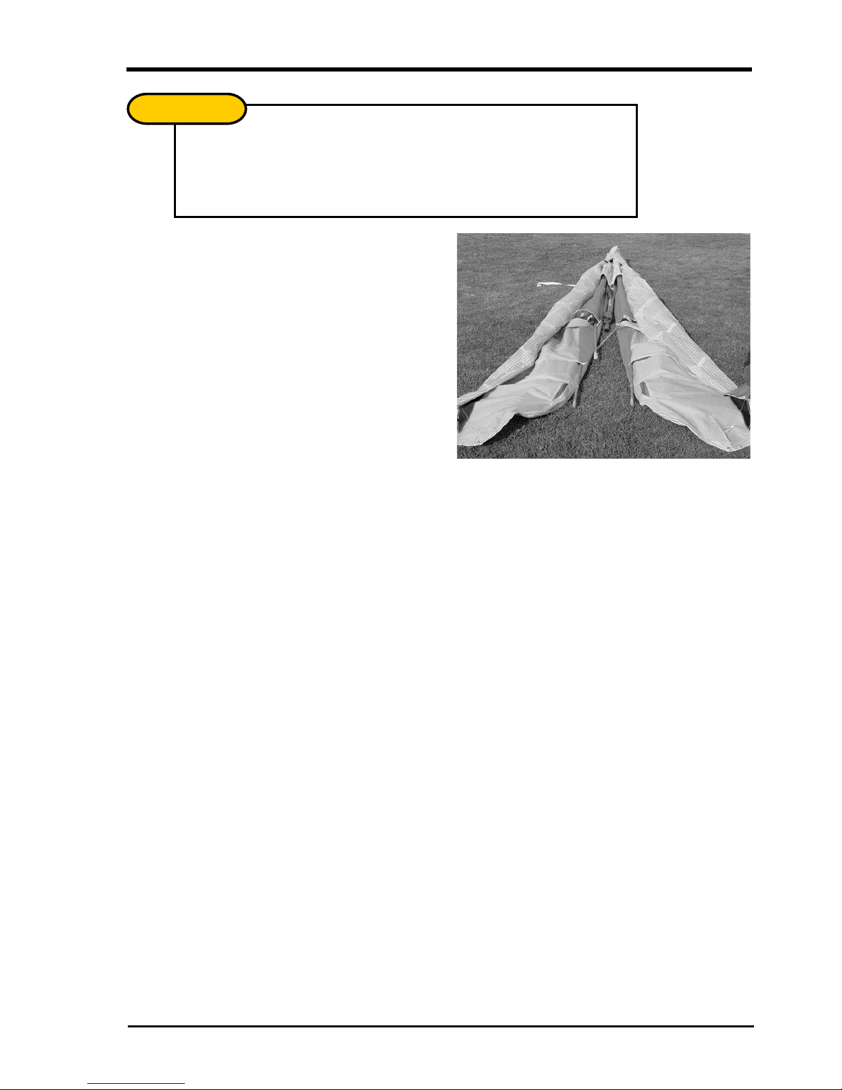
Picture 5
Assembled glider
showing dive sticks
extruding from under
surface zippers.
The inner and outer sprogs must exit the sail from the large cord wise zippers.
The zippers must be opened when the glider is in standard break down form
with both sprogs folding toward the wing tip outside the sail.
IMPORTANT
!
LITESPEED RX OWNERS MANUAL
12 Version 2
ASSEMBLY PROCEDURES
1. Place the glider on the ground, zipper up. Open the bag, undo ties, remove A-frame
bottom padding and battens.
2. Assembly the A-Frame.
Picture 6
Standard uprights and
base bar assembly.
Roll the glider over so that
it is standing on the
control frame.
3. Roll the glider over so that it is standing on the control frame.
Picture 7
Roll the glider onto the
A-frame and attach the
front wire to the Bailey Block.
Take special care with the wires, the Litespeed RX features 1x19 cable which
can easily be kinked unless special care is taken.
NOTE
!
With standard uprights, the uprights will naturally toe-in as shown in
Picture 6. Hold the base bar and the upright, twisting the upright so the
connection lines up.
NOTE
!
LITESPEED RX OWNERS MANUAL
Version 2 13
After initial assembly it is suggested that the nose batten be left in but pulled
out slightly and left beside the nose plate for pack-up. Check that the nose
batten sits over the lug on the keel securely.
NOTE
!
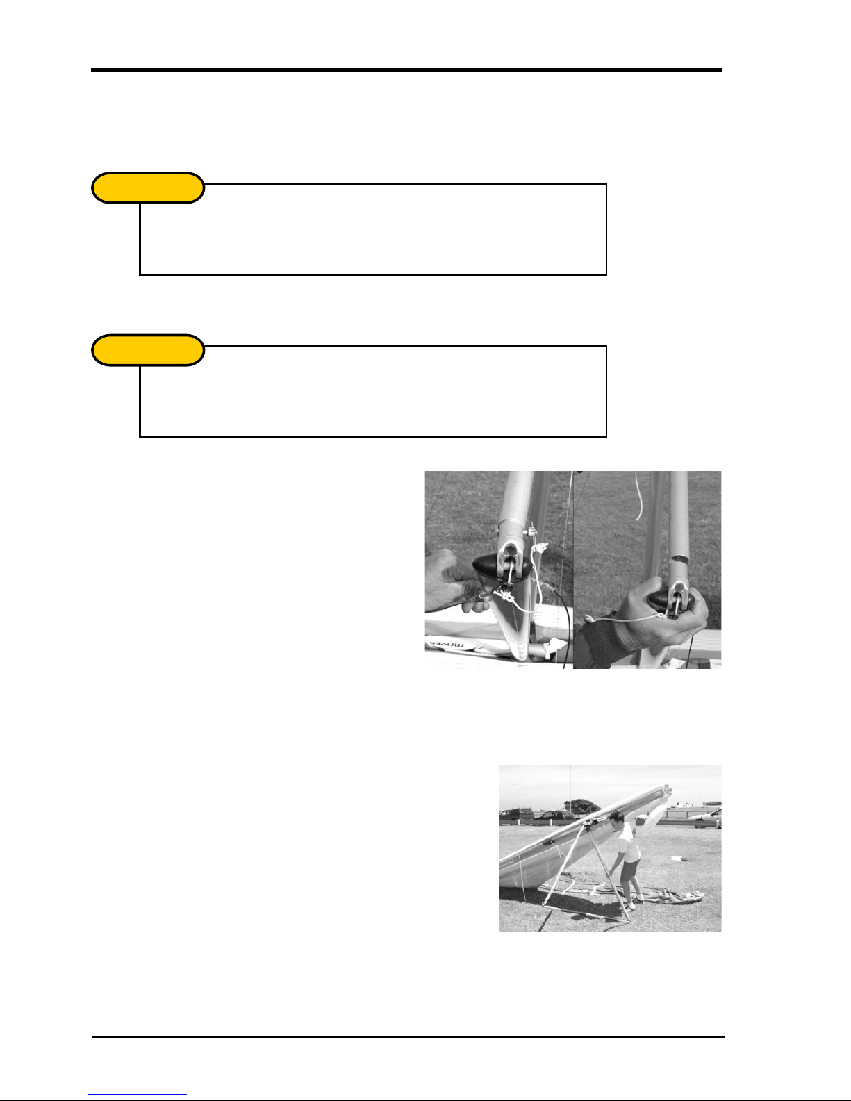
4. Insert the ring of the lower front wires in the Bailey Block making sure that the spring
is firmly locked and the wires untwisted.
Picture 8
Attaching the front wires to the Bailey Block.
5. Insert the nose batten. The batten may need some “feeding” through the Sail by
pulling the sail forward to remove any wrinkles as the batten slides into its pocket.
Picture 9
Insert nose batten.
6. Carefully spread each wing making sure that you do not raise them above the keel.
Picture 10
Spread the wings.
Check bottom wires are not twisted or kinked.
NOTE
!
LITESPEED RX OWNERS MANUAL
14 Version 2
DO NOT USE EXCESSIVE FORCE WHEN TENSIONING THE
GLIDER.
If excess force is encountered check:
!The side wires are not twisted or kinked
!The cross bar retainer wire is not caught on the nose plate assembly
!The floating cross bar centring wire is not caught on a cross bar
assembly junction
!The pull back wire or VG pulleys are not caught in the hang loop assembly
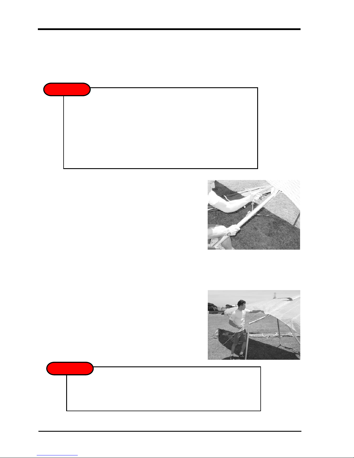
7. To tension the crossbar, pull the cord coming out of the keel aft of the sail.
Check that the cable and rope are not twisted and that the spring lock is firmly
locked. In strong winds the glider can be particularly difficult to tension. Have a
helper gently raise and pull one wing, this reduces the pressure on the centre
section and allows it to slide more freely.
Picture 11
Tension the glider.
8. The Litespeed RX is equipped with a removable keel aft section. The glider can be
left resting on it, facilitating the fitment of the washout struts, and battens. If desired,
the glider may now be raised onto its keel to complete the assembly. This also
assists with keeping the sail clean by keeping the tips off the ground.
Picture 12
Raising the glider onto the keel can make assembly
easier and keeps the sail clean.
WARNING
!
The glider may fall to one side if pushed or blown by the wind - this may result in
wing tip damage. It is recommended that you only use on flat level ground and
in nil wind. Use with care!
WARNING
!

LITESPEED RX OWNERS MANUAL
Version 2 15
9. Insert battens gently from the root towards the mid span, battens 1-6 only. Use only
gentle pressure when inserting the battens, this will greatly extend the longevity of
the batten pockets. Red tipped numbered battens are for the left wing, green for the
right, and blue the under surface.
Picture 13
Insert battens #1 to #6
10. Open zipper at sail tip to allow access to inside of sail. Slide carbon fibre rod
through end of sail and locate in the end of the leading edge. Ensure that the carbon
fibre rod is pushed hard against its stop.
Picture 14
Inserting tip and fitting aluminium cap.

LITESPEED RX OWNERS MANUAL
16 Version 2
11. Fit aluminium cup of the tip lever to the end of the tip rod and tension tip by rotating
the flat end of the tip lever inboard. For extra leverage, place your thumb through the
loop that is attached to the end of the tip lever. Make sure the tip lever is locked
against the tip rod. Close the zipper.
Picture 15
Tension the fibre glass wing tip.
12. Insert the remaining mainsail battens, 7 to 11.
13. Locate the inner and outer wire braced dive struts by placing them inside the sail,
below the webbing loop. Note that the action of closing the cord-wise zipper creates
the loop necessary to hold the strut in place.
14. Insert the under surface battens (blue) into their respective pockets.
15. Fit the nose fairing using the Velcro to keep a clean trim finish.
Picture 16
Fitting the nose cone.
Make sure the tip lever is consistent on both sides. The tip lever should either
be above or below the tip rod when locked in place.
NOTE
!
Do not forget this step as it is necessary for stability.
IMPORTANT
!

LITESPEED RX OWNERS MANUAL
Version 2 17
PRE-FLIGHT CHECK
You must look inside the sail to check many of the important structural components. You
should develop a consistent routine that incorporates all the necessary checks. If you
are distracted during the routine, you should start again to ensure nothing has been
missed.
1. As you should have already attached your harness to the glider, check that it is set
up correctly. Ensure that your parachute is well maintained and stowed appropriately
and that the bridle runs cleanly to the carabineer which is attached vertically to the
hang loop. If your harness height from base bar needs adjustment, it is best to
acquire the correct length loop from your Moyes dealer.
2. Move up to the suspension system and verify that the dingle-dangle is rotated
perpendicular to the keel and is free from the nose batten pocket. Check the hang
loop and backup.
3. Open the under surface zip and inspect the cross-bar retainer wire. Pull the VG on
and off a few times to check that the crossbars are moving freely and the VG system
is operating smoothly and is tied firmly to the clip. Inspect the interior of each wing,
looking at the back side of the leading edges, the crossbar, and the crossbar
junctions. Check that the cross bar centring wire is free. This wire is partly loose in
VG full off and should become tight when VG is 3/4 on.
4.
5. Check the apex of the control frame ensuring all nuts are secure and thread is
showing beyond the nut on the bolt end.
6. Sight along keel and move to the nose section, checking all nuts and bolts.
Test nose catch and ensure keel batten is located correctly. Re-attach nose fairing.
7. Sight along each leading edge to confirm a similar amount of leading edge
deflection (curve). Uneven curves will indicate a bent or damaged leading edge.
While sighting down the leading edges check each wing for dive stick symmetry, i.e.
equal twist for left and right wing.
Check that all internal Velcro’s are attached and are of equal length. If one
side is disconnected or too loose, it may cause a significant turn.
IMPORTANT
!
It is easiest to inspect for tube damage when wings are slightly opened with
no battens in the sail. The entire length of the leading edge tubes can be
easily seen at this stage of the set up procedure through the under surface
zippers and centre zip. We recommended checking for dents or bends at this
stage of set up before each flight.
NOTE
!

LITESPEED RX OWNERS MANUAL
18 Version 2
8. Move out along the wing looking and feeling for any damage. Open the zip where
the side wires enter the sail and check that bottom wires are not kinked, twisted or
damaged. Check the cross-bar/leading edge junction bolts and nuts and check that
the ball joint is not bent. Close zip on inspection port.
9. Open the long cord-wise zippers at sprog location and check both the front and rear
of each dive strut. Check that the wires are not kinked or twisted and check that the
ball joint thread is not bent. Close zip.
10. Continue out to wing tip and make sure the tip levers are properly installed and that
the zipper is closed.
11. Check all battens as you move along the trailing edge and be sure that the flip-back
tips are secure inside of the trailing edge pocket.
12. At the keel, check the top VG rope and the cross-bar restraining wire. Check that
rear wires are properly secured by the Bailey Block bolt.
13. Moving across to the other wing, repeat the process as you work your way back to
the nose of the glider. Carefully check the front bottom wires and nose catch before
inspecting the base of the control bar. Check bottom side wires for frayed strands
between thimble and inner nico, and just outboard of the outer nico.
14. Ensure that the control frame assembly bolt passes through the base bar and the
corner knuckle.
15. Check the rigging, nuts, and bolts are in good order and that the VG rope is
threaded through the jam cleat and is secure.
16. Re-check harness, hang loops, and carabineer.
17. When finally preparing to fly, do a proper hang check ensuring that legs are through
leg loops, that harness zippers work, and that all buckles or clips etc. are closed and
working. Look again at your hang loops and carabineer(s).
This manual suits for next models
3
Table of contents
Other moyes Aircraft manuals


