Wills Wing RamAir 154 Application guide

1
154 - 146
Owner / Service Manual
500 West BlueridgeAve Orange, CA 92665 Phone (714) 998-6359 FAX (714) 998-0647
Revised 3/24/94 - 5th Edition
Copyright © 1993 by Sport Kites, Inc. dba Wills Wing, Inc. All rights reserved. No part of this manual
may be reproduced in any form without the express written permission of Sport Kites, Inc., dba Wills
Wing,Inc.

2
Table Of Contents
Page
Introduction ........................................................................................................ 3
DisclaimerandWarning ..................................................................................... 4
TechnicalInformation andPlacarded Operating Limitations ............................... 4 - 6
ShippingBreakdownand Re-Assembly ............................................................. 7 - 9
Glider Set-Up and Preflight................................................................................ 9 - 22
LaunchingandFlying.......................................................................................... 23
Trimming The Glider In Pitch and Speeds to Fly ................................................ 23 - 27
Using The VG System ....................................................................................... 28 - 29
Landing .............................................................................................................. 29 - 31
Breakdown ........................................................................................................ 31 - 32
Stability Systems ............................................................................................... 32 - 38
Maintenance ...................................................................................................... 38 - 39
RemovingandRe-InstallingThe Sail.................................................................. 39 - 42
Tuning ................................................................................................................ 42 - 43
Car Top Mounting .............................................................................................. 43
ClosingMessage ............................................................................................... 44
ComplianceVerification SpecificationSheets..................................................... 46 - 47
Frame Plans and Exploded Views ..................................................................... 48ff

3
INTRODUCTION
Thank you for purchasing a Wills Wing glider, and welcome to the world wide family of Wills
Wing pilots. We are a company of pilots and aviation enthusiasts, and our goal is to serve your
flying needs now and in the future, as we have done for pilots throughout the world since 1973.
We encourage you to read this manual thoroughly for information on the proper use and
maintenance of your Wills Wing glider. If at any time you have questions about your glider, or
about any aspect of hang gliding that your Wills Wing dealer cannot answer, please feel free to
give us a call.
We wish you a safe and enjoyable flying career, and, once again, welcome aboard!
Rob Kells, Mike Meier, Linda Meier, and Steve Pearson
Wills Wing, Inc.

WILLS WING INC. 500 West Blueridge Orange CA USA 92665-4206
Fax (714) 998-0647 Phone (714) 998-6359
RamAir 154/146 Owner's Manual Addendum:
Bridle Setting Measurements and Limits - July 4, 1994
In order to check your bridles for proper adjustment, the following measurement
procedure should be used:
On a flat and level floor, set up the glider completely as if you were going to fly it, and
allow it to rest on the control bar basetube and rear end of the keel. Using a light weight
thread, run a length of thread from the rear tip of each bridle batten over the keel tube to
the corresponding batten on the other side. Attach the thread to the batten end by tying
an open loop in the end of the thread, and looping it over the batten tip (this will result if
done properly in the thread aligning itself with the centerline of the batten tube). Make
sure to adjust the thread length so that the thread is stretched under tension, and
therefore does not sag measureably across the span of its length.
At each of the three VG settings, measure the height above the top surface of the keel
tube of each of the four threads. To insure that the glider has the minimum required
pitching moment values, these measurements should be those shown in the chart
below, plus or minus 3/8”.
Bridle @ #4 Batten
154 146 Bridle @ #5 Batten
154 146 Bridle @ #6 Batten
154 146 Bridle @ #7 Batten
154 146
VG
Loose 2” 2 5/8” 3 1/2" 3 1/2” 4” 3 3/4” 4 3/8" 4”
VG
Middle
1/2" 1 3/8” 2 3/8" 2 3/8” 2 7/8” 2 3/4” 3 1/8” 2 7/8”
VG
Tight Intersects 1/16”
Tube 1 3/8" 1 1/8” 1 7/8” 1 3/4” 2 1/4” 2”
If, on either model, the measurements are less than those shown, the adjustment of the
lower compensator attachment rope should be shortened as necessary.
The measurements can generally be up to 3/8" greater than those shown (bridles
adjusted tighter) without the bridles being so tight that they interfere with the glider's
flight characteristics. Refer to the rest of the material on bridle adjustment in this
manual.

TECHNICAL BULLETIN
Wills Wing Inc 500 West Blueridge Ave Orange, CA 92865 Ph/Fax (714) 998-6359/0647 http://www.willswing.com
Bulletin #: TB940501 RamAir Pitch Stability Modification Date: 5/25/94 Page 1 of 3
Revised 6/1/94 Destroy all previous copies
Introduction
On May 12, 1994 Wills Wing issued a temporary grounding order for the RamAir 154. This order was issued following a turbu-
lence induced tumble and subsequent structural failure in Germany, and reports of three other turbulence induced upsets without
structural failure. Because of these incidents, both the DHV and Wills Wing retested the RamAir 154 on their test vehicles. In both
cases, areas of noncompliance were found at some intermediate VG settings. As of the date of this bulletin, no incidents or
problems have been reported on the RamAir 146.
Wills Wing has since developed a retro-fittable modification. This modification has been tested and shown to substantially
increase the RamAir 154's and RamAir 146's margin of compliance with U.S. H.G.M.A. standards and also improve some qualitative
handling characteristics. The modification includes a new bridle set, a bridle compensator adjustment, the addition of reflex to the
profile root area battens and a CG/hang loop adjustment. The parts are available free of charge through Wills Wing dealers world
wide. Installation instructions follow.
Batten Reflex Modification
The 154 has reflex added to 4 battens: no. 8 through no. 11, the 146 has reflex added to 3 battens: no. 8 through no. 10. Refer to
figure no. 1. Measure and mark each batten at distance "A". Bend each batten in a smooth radius over a 3 inch length centered on
the mark. Verify the reflex specification "B" using the replacement batten chart available from Wills Wing. Use the X's, and the
unchanged root and #7 battens to align the overlays to the chart. Use care to keep the reflex bend in the same plane as the nose
area camber. You will achieve better quality results if you work on a large flat unobstructed surface.
Batten #8 #9 #10 #11 (154 only)
Distance A 12 in [30.5 cm] 13 in [33 cm] 14 in [35.5 cm] 15.5 in [40 cm]
Distance B RamAir 154 1 in [2.5 cm] 1-1/2 in [3.8 cm] 1-3/4 in [4.5 cm] 2-1/8 in [5.5 cm]
Distance B RamAir 146 1-3/8 in [3.5 cm] 1-3/4 in [4.5 cm] 2-1/4 in [5.7 cm] NA
Figure no. 1
Bridle Installation
Remove the original bridle set from the #4, #6 and #8 batten stations. Save the 6 bridle balls. Install the retrofit bifurcated bridle
set at the #4, #5, #6 and #7 stations. Install the cable loops through the original bridle anchor grommets at the #4 and #6 stations,
and through the outboard of the two batten tension grommets at the #5 and #7 stations. Refer to figures no. 2 and no. 3. Check that

TECHNICAL BULLETIN
Wills Wing Inc 500 West Blueridge Ave Orange, CA 92865 Ph/Fax (714) 998-6359/0647 http://www.willswing.com
all cables are free from twists. Be sure to pre-flight the bridles at the #5 & #7 battens carefully, as there is an increased chance of
the bridle ball not fully seating in the grommet because of the batten string. Please return your orignal bridle set to Wills Wing.
Figure no. 2 Original Configuration Figure no. 3 Modified Configuration
Compensator Adjustment
Adjust the perlon rope compensator link (near the crossbar junction) to the following specifications, measured between the
centers of the holes in the tangs. Refer to the illustration below. Use overhand knots onlyprevious "figure 8" type knots have
been known to slip.
RamAir 154 2.75 inches / 7.0 cms
RamAir 146 4.75 inches / 12.0 cms
Tighten both knots firmly, using pliers if necessary. Support the rear keel at the rear wire station and pull down on the bridle
compensator clip at the top of the kingpost with 50-75 lbs of force. Recheck the specification.
Set the VG to the full loose setting. Check the bridles at each batten station by hooking a tape measure over the top front wire at
the kingpost top and reading the measurement at the trailing edge hem, at the intersection with the pencil line on the sail which
marks the batten pocket application line. Your measurements should be those shown below, plus or minus 1/4 inch.
Model #7 #6 #5 #4
RamAir 154 97 in [246.4 cm] 117-1/4 in [297.8 cm] 138-1/2 in [351.8 cm] 160-1/8 in [406.7 cm]
RamAir 146 93 in [236.2 cm] 113 in [287 cm] 134 in [340.4 cm] 155-1/2 in [395 cm]
Bulletin #: TB940501 RamAir Pitch Stability Modification Date: 5/25/94 Page 2 of 3

TECHNICAL BULLETIN
Wills Wing Inc 500 West Blueridge Ave Orange, CA 92865 Ph/Fax (714) 998-6359/0647 http://www.willswing.com
Hang Loop / CG Adjustment
Reflex slows the glider trim speed approximately three mph. Mark the location of the rear of the hangloop on the keel. Adjust the
hang loop 1/2 inch forward. Check that the forward hang loop adjustment tang is pinched firmly against the keel so loop can not
shift position.
Flight Test Verification
A flight test verification is essential for proper adjustment of the bridle system. The shadow of the bridle cables can be seen on
the sail when flying in direct sun exposure. Perform a shallow circling turn away from obstacles or traffic. When the shadows of the
cables are visible on the sail, lightly shake the control bar basetube. The degree of movement will indicate the amount of slackness
in the cable. At VG loose, the slackness should progress from just slack to slack, inboard to outboard. VG tight, the progression
should be from snug to just slack (slightly tighter than VG loose). Please refer to your Owner/Service Manual under the section
Test Flight and Checking The Bridles for definition of the terms slack and snug.
If the outboard bridles become tight before VG tight, pitch bar pressure at high speeds will be higher VG tight than VG loose,
and handling in rough air will be adversely affected. If the bridles are looser than specified, optimum stability will not be achieved.
A final evaluation of the bridle adjustment should be made by flying the glider in a steady state, pilot full forward dive at each of
three settings from VG loose to tight and checking the pitch bar pressures. This should only be done in smooth air. The pilot full
forward position should be approached slowly and gradually so that zooming and hysteresis in speed are avoided. At steady state
pilot full forward, the pitch pressure should fall in the range indicated on the graph below. As a reference, the VG loose pitch
pressure on a RamAir is approximately 1/2 to 2/3 of an HPAT. The pitch pressure will decrease slightly and progressively as VG
engagement is increased, as indicated on the graph.
Please note that new RamAir 154 bridle system does not induce reflex in the inboard sail at VG tight position as it did with the
original bridle set.
Modification Verification Card
Please complete and return the attached Modification Verification Card promptly. This information will provide the basis for
tracking the progress of the upgrade and providing you with supplemental information or instructions if necessary.
Glider Owner's Manual
Please staple this Technical Bulletin into the rear of your RamAir Owner's Manual for future reference.
In Closing
We apologize for any inconvenience and frustration this action has caused to our valued customers. Please feel free to contact
Wills Wing if you have any questions.
Bulletin #: TB940501 RamAir Pitch Stability Modification Date: 5/25/94 Page 3 of 3

4
DISCLAIMERAND WARNING
Hang gliding is a form of aviation. Like any form of aviation, its safe practice demands the
consistent exercise of pilot skill, knowledge of airmanship and weather, judgment and atten-
tion at a level which is appropriate to the demands of each individual situation. Pilots who do
not possess or exercise the required knowledge, skills and judgment are frequently injured
and killed. The statistical rate at which fatalities occur in hang gliding is approximately one
per thousand participants per year.
The Federal Aviation Administration does not require a pilot’s license to operate a hang
glider. Hang gliders and hang gliding equipment are not designed, manufactured, tested or
certified to any state or federal government airworthiness standards or requirements. Fed-
eral Aviation Regulation Part 103 states in part, "ultralight vehicles are not required meet the
airworthiness certification standards specified for aircraft or to have certificates of airworthi-
ness" and "operators of ultralight vehicles are not required to meet any aeronautical knowl-
edge, age, or experience requirements to operate those vehicles or to have airman or medi-
cal certificates." Wills Wing hang gliding products are not covered by product liability insur-
ance. As a hang glider pilot, you are entirely responsible for your own safety. You should
never attempt to fly a hang glider without having received competent instruction. We strongly
recommend that you not participate in hang gliding unless you recognize fully and wish to
personally assume all of the associated risks.
Please fly safely.
Wills Wing, Inc.
TECHNICAL INFORMATION AND PLACARDED OPERATING LIMITATIONS
The RamAir 154 and 146 have been tested and found to comply with the 1993 Hang Glider
Manufacturers Association (HGMA) Airworthiness Standards. These standards require:
1) A positive load test at root stall angle of attack at a speed equal to at least the great-
est of:
a) 141% of the placarded maximum maneuvering speed
b) 141% of the placarded maximum rough air speed
c) 123% of the placarded speed never to exceed
for at least three seconds without failure.
The required speed for the RamAir 154 and 146 for this test was 74 mph.
2) A negative 30 degree angle of attack load test at a speed equal to at least the great-
est of:
a) 100% of the placarded maximum maneuvering speed
b) 100% of the placarded maximum rough air speed
c) 87% of the placarded speed never to exceed
for at least 3 seconds without failure.
The required speed for the RamAir 154 and 146 for this test was 52 mph.

5
3) A negative 150 degree angle of attack load test at a speed equal to at least the
greater of 30 mph or 50% of the required positive load test speed for at least 3 seconds
withoutfailure.
The required speed for the RamAir 154 and 146 for this test was 37 mph.
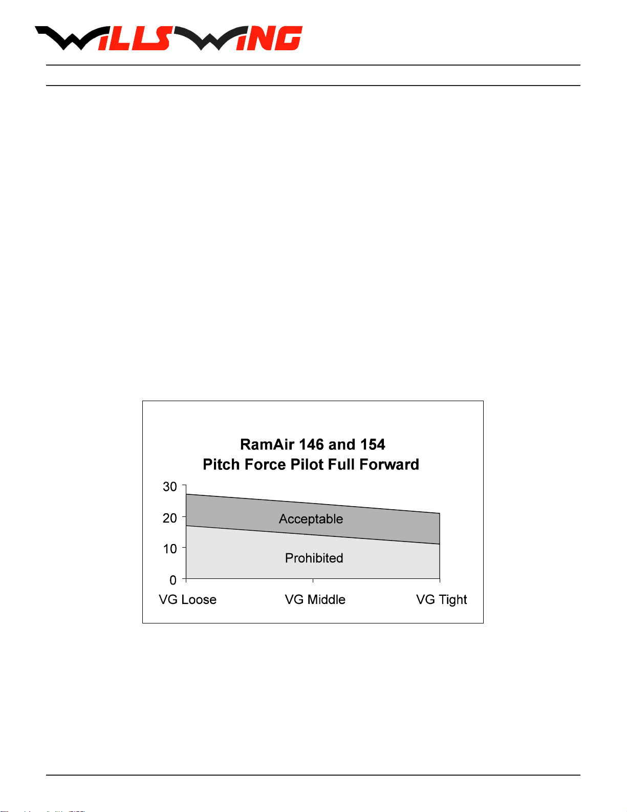
4) For the RamAir 154 and 146, with a Vne of 60 mph, pitch tests at speeds of 20 mph,
40 mph and 60 mph which show the glider to be stable over a range of angles of attack from
trim angle to 20 degrees below zero lift angle at 20 mph, and from trim angle to 10 degrees
below zero lift angle at 40 mph, and from 10 degrees above zero lift angle to zero lift angle
at 60 mph.
5) Flight maneuvers which show the glider to be adequately stable and controllable
throughout the normal range of operation.
NOTE: The RamAir 154 and 146 have been designed for foot launched soaring flight. They
have not been designed to be motorized, tethered, or towed. They can be towed success-
fully using proper procedures. Pilots wishing to tow should be USHGA skill rated for towing,
and should avail themselves of all available information on the most current proper and safe
towing procedures. Suggested sources for towing information include the United States
Hang Gliding Association and the manufacturer of the towing winch / or equipment being
used. Wills Wing makes no warranty of the suitability of the glider for towing.
Flight operation of the RamAir should be limited to non aerobatic maneuvers; those in which
the pitch angle will not exceed 30 degrees nose up or nose down from the horizon, and the
bank angle will not exceed 60 degrees. The RamAir is generally resistant to spinning, but will
spin from a stalled turn if the VG is adjusted at or near the tight end of the range, and the
rate of application of pitch is moderately rapid. The RamAir can be induced to spin at any
VG setting. Recovery from a spin requires unstalling of the wing, and it is therefore critically
important that in the event of a spin, no application of nose up pitch control be held. The
RamAir will recover from a spin once control pressures are relaxed. As the nose lowers and
the angle of attack is reduced, the stall will be broken and the spin will stop. However, such
recovery will consume significant altitude, and will result in the glider assuming an unpredict-
able heading. Recovery from a spin may therefore involve a flight trajectory which intersects
the terrain at a high rate of speed. An aggravated spin could result in loss of control, in flight
inversion, and structural failure. Therefore no attempt should ever be made to deliberately
spin the glider. The RamAir provides the pilot with a high degree of pitch authority, in combi-
nation with a very low twist sail. As a result, it is possible by pushing fully out on the bar to
produce a very aggravated and severe stall, the recovery from which may involve very
severe pitch down rotation, the pilot going weightless, and the glider recovering via an unpre-
dictable trajectory with a significant altitude loss. Therefore, full arms extension aggravated
stalls should not be induced except on landing flare.
The maximum steady state speed for a prone pilot in the middle of the recommended weight
range full forward on the control bar with the VG set full tight is approximately 63 mph for
the RamAir. The placarded speed never to exceed for the RamAir is 60 mph. This speed will
be achieved with the control bar basetube approximately two inches below the waist.
Theplacarded maximum maneuveringspeed, andthe placarded maximumrough air speed
of the RamAir are each 52 mph. This speed will be achieved with the control bar basetube

6
approximately four inches above the waist. This speed should not be exceeded in anything
other than smooth air. No abrupt maneuvering or control inputs should be made at anything
above this speed.
The stability, controllability, and structural strength of a properly maintained RamAir have
been determined to be adequate for safe operation when the glider is operated within all of
the manufacturer specified limitations. No warranty of adequate stability, controllability, or
structural strength is made or implied for operation outside of these limitations.
The stall speed of the RamAir at maximum recommended wing loading is 25 mph or less.
The top (steady state) speed at minimum recommended wing loading for a prone pilot with a
properly designed and adjusted harness is at least 46 mph. All speeds given above are
indicated airspeeds, for a properly calibrated airspeed indicator mounted in the vicinity of the
pilot. Wills Wing provides such an airspeed indicator with the glider. It is strongly recom-
mended that the pilot fly with such an airspeed indicator. Refer to the section on using the
airspeed indicator for further information on speeds to fly.
The recommended hook in pilot weight range for the RamAir is:
RamAir 154: 160 - 270 lbs. RamAir 146: 145 - 260 lbs.
Be advised that pilots with hook in weights of less than 20 lbs above minimum will find the
RamAir significantly more demanding of pilot skill to fly, and that pilots hooking in within 20
lbs of the maximum will experience some relative degradation of optimum sink rate perfor-
mance due to their higher wing loading.
A minimum USHGA Advanced (IV) level of pilot proficiency is required to fly the RamAir
safely. Pilots are advised that the optimum proficiency level for the RamAir is higher than the
minimum recommended. Operation of the glider by unqualified or under qualified pilots may
bedangerous.
Operating the RamAir outside of the above limitations may result in injury and death. Flying
the RamAir in the presence of strong or gusty winds, or turbulence may result in loss of
control of the glider which may lead to injury and death. Do not fly in such conditions unless
you realize and wish to personally assume the associated risks. Wills Wing is well aware
that pilots have, and continue to perform maneuvers and fly in conditions which are outside
the recommended operating limitations stated herein. Please be aware that the fact that
some pilots have exceeded these limitations in the past without dangerous incident does not
imply or insure that the limitations may be exceeded without risk. We know for a fact that
gliders which meet all current industry standards for airworthiness can and do suffer in flight
structural failures, both as a result of turbulence, and as a result of various maneuvers
outside the placarded operating limitations, including, but not necessarily limited to aerobat-
ics. We do not know, and cannot know, the full range of maneuvers or conditions which may
cause the pilot’s safety to be compromised, nor can we test the glider in all possible circum-
stances.

7
RamAir BREAKDOWN PROCEDURE FOR SHIPPINGAND RE-ASSEMBLY
PROCEDURE
The RamAir 154 can be broken down to approximately 13.5 feet by removal of the rear
leadingedges.
STOP: DO NOT REMOVE ANY OF THE CLEVIS PINS OR SCREWS IN THE VI-
CINITY OF THE REAR LEADING EDGE STEP DOWN JUNCTION.
1) The front leading edge of the RamAir is 60 mm (2.36") tubing, into which slides the rear
leading edge of 50 mm (1.97") tubing, with an overlap of 6". Because of the great difference
in diameters of the front and rear leading edges, they are not concentric; that is they do not
share a common axial centerline. Instead, the 50 mm and the 60 mm tubes are tangential
(they contact each other) on a line along the forward edge of the leading edge, just below
the horizontal centerline. (See diagram).Inside the 60 mm front leading edge, six inches from
the rear end, is a 58 mm diameter ryton plastic crescent reducer which is secured in place
by a 3/16" clevis pin which passes all the way through the 60 mm front leading edge. (See
diagram). DO NOT REMOVE THIS PIN.
A second crescent in located at the aft end of the 60 mm front leading edge, where the 50
mm rear leading edge exits. This crescent is held in place with a screw. DO NOT REMOVE
THISSCREW EITHER.
A reinforcing inner sleeve is located
inside the 50 mm rear leading edge, and
is secured in place by a clevis pin. DO
NOT REMOVE THIS PIN EITHER.
The rear leading edge is slotted at it’s
forward end, such that the slots engage
around the clevis pin which secures the
forward crescent.
STOP: THE REAR LEADING EDGE
WILL PROPERLY ENGAGE THE
CLEVIS PIN IN ONLY ONE AXIAL
ORIENTATION. IF INSERTED WITH
180 DEGREES ROTATION, IT MAY
SEEM TO BE ENGAGING, DUE TO
THE FLARE AT THE ENDS OF THE
SLOTS. HOWEVER, FORCING THE
TUBE IN IN THIS ORIENTATION
WILL DAMAGE THE TUBE, SPLIT-
TING THE SLOT OPEN.

8
TO BREAK DOWN THE LEADING EDGES FOLLOW THESE STEPS:
1) Lay the glider on the ground or floor, unzip and remove the bag and remove the velcro
ties. Undo the velcros which hold the sail around the sail mount plug and pull the sail rear-
ward at each tip to dismount the sail from the rear leading edge.
2) Obtain an indelible marker. Mark the rear leading edges left and right (remember that left
and right are reversed if the glider is lying “on it’s back”, upside down. Push the sail up to
where you have uncovered the point where the rear leading edge exits the front. Trace
around the circumference of the 50 mm rear leading edge just along the aft face of the
crescent reducer so as to mark the point at which the rear leading edge is fully engaged in
the front.
3) Scribe a line along the leading edge which crosses the front to rear leading edge junction
at the point on the circumference where the front and rear leading edges are tangent. This
will help to align the rear leading edge during re-assembly.
4) On a late model sail (after September 1993) the mylar can be removed at this time.
Remove the top plastic kingpost cap and disconnect the top side wire from the kingpost.
Replace the cap. Pull the top side wire through to the inside of the sail. Pull the sail back
down the length of the leading edge but do not remount it to the rear. Pull the mylar out from
the rear of the mylar pocket, curling it under where it exits so that it will fit through the open-
ing. If the mylar sticks, work up and down the edges of the mylar along the mylar pocket,
breaking the edges of the mylar away from the seamstick tape in the seams. (On early
model sails, the myar can only be removed with the sail completely off the frame by sliding it
out of the front of the mylar pocket from inside the double surface through the bottom sur-
face center zipper.)
5) Spray silicone spray lubricant on the rear leading edge at the point where it exits from the
front.
6) Pull the rear leading edge straight aft to disengage it from the front. Put tape on the sharp
edges of the front end of the rear leading edge tubes.
7) Carefully fold the rear of the sail over against the front, and replace the bag on the glider.

9
RE-MOUNTING THE REAR LEADING EDGES
1) Make sure you are mounting the correct leading edge rear into the correct front (check
the “right” / “left” designation.
2) Spray the forward six inches of the rear leading edge with silicone spray lubricant.
3) Slide the rear leading edge into the front, lining up the rotational alignment marks you
made during breakdown, until the rear engages fully in the front leading edge, as indicated
by the circumferential scribe made at the exit point of the rear leading edge during break-
down.
4) Pull the sail down the leading edge and re-install the mylar if removed. The mylar is most
easily installed by attaching it to a long pole and pushing it into the pocket.
5) Re-install the top side wire if removed.
6) Remount the sail to the rear leading edge, making sure to align the sail mount webbing
squarely in the slot and attach the securing velcros.
STOP: THE SAIL IS MOUNTED TO THE LEADING EDGE BY THE INNER (FOR-
WARD) OF THE TWO LOOPS OF WEBBING. THE OUTER LOOP IS A PULL
HANDLE ONLY.
You may find it helpful to use a large, flat bladed screw driver to pry the sail mount webbing
over the end of the leading edge tube and into the slot. Take care not to damage the web-
bing.

10
RAMAIR Set-Up Procedure
The RamAir has been specially designed to set up quickly and easily either on the control
bar or flat on the ground. We will first cover the steps for setting up on the control bar.
1) Lay the glider on the ground, with the bag zipper up, with the nose into the wind.
2) Undo the zipper, remove the battens, remove the protective pad at the rear wire station
on the keel, and remove the
control bar bag.
3) Unfold the control bar legs
and straighten the fold in the
foldingbasetube.
Preflight the folding basetube center
hardware at this time, checking that
the nuts and coil spring pins are
secure, and that the tangs are
straight and in good condition.
Slide the basetube center sleeve
over the center joint until it is posi-
tioned between the button spring
pins. (Note: If you plan to clamp
instruments to the basetube center,
position the center sleeve so that
one button passes through the hole
near one end of the sleeve, which
will secure the sleeve against rota-
tion.
4) Grasp the swan lever, attached to the forward end of the swan catch wire, and pull it
towards the nose while holding the basetube and keeping the control bar aligned as nearly

11
centered side to side with the keel as possible. The control bar apex bracket will slide on the
keel track until it comes up against the stop at the forward end of the track. If the apex
slider resists sliding forward, wiggle the basetube back and forth slightly to free it.
STOP: If the apex bracket will not slide forward, check to see that a bottom side
wire is not hooked around the head of the keyhole bolt at the rear wire station
on the keel.
5) Insert the rounded end of the swan catch lever (without the thumb handle extension) into
the rear pin channel in the swan catch bracket on the bottom of the noseplate. (The pin
should be retracted and held in place by the flat swan spring. If it is not, retract the pin first).
As the swan lever end depresses the flat swan spring, the spring loaded swan catch pin will
be released. Align the hole in the lever with the pin, and allow the pin to slide through the
lever and through the other side of the swan catch channel.

12
STOP: Make sure that the rear swan catch pin is fully engaged in the swan
lever, and passes through and extends beyond the other side of the channel. An
inadvertent release of the swan lever from the swan catch channel in flight will
allow the control bar apex to slide rearwards causing a total lack of structural
support for the wings and a complete loss of control of the glider.
6) Flip the glider upright and set it on the
control bar, and remove the glider bag and
all velcro sail ties. Loosen the velcro at-
tachments on the tip cover bags, but do
not remove the bags at this time. If there is
more than eight mph of wind, or if the wind
is gusty, turn the glider 90 degrees to the
winddirection.
7) Spread the wings almost all the way. If
you have left the bridles attached, this will
automatically stand the kingpost upright. If
not, lift on the top side wire as you spread
the second wing, and the kingpost will stand up.
8) If the bridles have been detached, attach the bridle ring to the snap hook at this time,
taking care that there is not a twist or rotation in the bridle ring which causes the bridle line
to cross over one another.
9) Remove the battens from the batten bag, and check each batten for symmetry against
the corresponding batten from the other wing. Wills Wing convention is that black tipped
battens go in the right wing and white tipped battens in the left, except for the straight #1
plug on battens which all have black tips.
10) Install the cambered top surface battens in the sail, leaving out the shortest two on each
side (#2 and #3) for now. Each batten is secured by a double loop of the batten string.

13
Order of insertion is longest to shortest, from the root out. When inserting the inboard most
battens, lift the keel to ease the insertion. When these battens reach the back side of the
leading edge tube, it may be necessary to lift the sail along the batten pocket to facilitate
insertion of the batten all the way.
STOP: Insert the battens carefully, so as to minimize stress and wear on the
sail. Never insert or remove top surface battens with the crossbar tensioned
(except for up to the last four on each side) and never insert or remove battens
with heavy wind pressure on the top of the sail or in any condition which causes
the battens to slide with great resistance in the pockets.
11) Spread the wings all the way and check all cables for any twisted thimbles or tangled
cables. Check at this time that no bridle line is caught under the end of an adjacent batten.

14
12) At the rear of the keel, tension the crossbar by pulling on the top portion of the 4mm
accessory cord which passes through the white pulley on the rear of the sweep wire keyhole
channel. Drop the keyhole channel all the way down over the head of the keyhole bolt, and
let it slide forward into the locked position.
STOP: Never install the keyhole channel onto the keyhole bolt without making
absolutely sure that the channel is fully engaged on the narrow neck of the bolt
and slid forward into the fully locked position. An inflight disengagement of this
attachment will cause a complete loss of structural support of the glider and a
total loss of control.
13) Remove the wingtip protector bags, and remove the plastic wingtip fairings from inside
the bags. Install the last two curved battens on each side.

15
14) Install the plug-on #1 battens by inserting one end through the hole in the bottom surface
at the tip and engaging the forked batten tip on the clevis pin standoff on the back side of
the leading edge. Secure with a double loop of the 505 batten string.
15) At this time preflight the following from the open end of the wingtip:
a) The sail mount webbing - make sure that the inner loop of webbing is laying flat in
the bottom of the slot in the sail mount endcap.
b) The number one batten clevis pin and safety.
c) The clevis pin and safety just aft of the leading edge step down which secures the
48 mm inner sleeve in the rear leading edge.
d) The aft crescent reducer - make sure it is fully engaged in the 60 mm front leading
edge tube.
e) The front crescent reducer clevis pin and safety.
f) The crossbar / leading edge junction bolt castle nut and safety.
16) Install the plastic wing tip fairing. Before doing so, separate the neoprene from the
velcro to provide a space for the edge of the fairing to fit. Make sure that the fairing lodges
between the inside of the sail and the outside of the neoprene seal, and that the fairing is
fully inserted into the leading edge such that the velcro mates securely around the entire
perimeter of the tip fairing. While installing the tip fairing, support the aft tip of the number
one batten as necessary so as to equalize the tension around the perimeter of the open end
of the sail at the wing tip to insure that the sail mates properly to the tip fairing.

16
17) Go to the nose and tension the swan catch wire. This is most easily done by placing a
thumb under the lever handle on the swan lever and then pulling downwards on the swan
lever cable to pull the control bar apex slider fully forward against the stop. Then, as you
release tension on the cable, rotate the swan lever forwards and up until it clicks fully into
place and the forward spring loaded swan pin slides all the way through both the lever and
the hole in the far side of the channel. (This pin should have been held retracted by the flat
swan spring; if it was not, retract it before performing this operation.)
STOP: Make sure that the forward swan catch pin is fully engaged in the hole in
the swan lever, and passes through and extends beyond the other side of the
channel. An inadvertent release of the swan lever from the swan catch channel
in flight will allow the control bar apex to slide rearwards causing a total lack of
structural support for the wings and a complete loss of control of the glider.
Flying the glider with the front end of the swan lever detached will slacken the
wires on the glider reducing glider stability and control.
18) By lifting up and back on the nose batten strings, push the nose battens fully back into
the sail so that the tips rest on top of the noseplate. Look into the noseplate and pre-flight
the nosebolt nuts and the safety on the bolt securing the top front wire.
19) Install the nosecone taking care to align
it so that it lies flat on the top and bottom of
the sail.
This manual suits for next models
1
Table of contents
Other Wills Wing Aircraft manuals

Wills Wing
Wills Wing Skyhawk User manual

Wills Wing
Wills Wing Duck User manual

Wills Wing
Wills Wing Sport 2 155 Application guide

Wills Wing
Wills Wing Condor 330 User manual

Wills Wing
Wills Wing Alpha 180 Application guide

Wills Wing
Wills Wing HP II Instruction Manual

Wills Wing
Wills Wing Fusion 141 Application guide

Wills Wing
Wills Wing T2 144 Application guide

Wills Wing
Wills Wing Ultra Sport 135 Application guide

Wills Wing
Wills Wing HP 170 Application guide