Bell&Howell 013300 User manual

Disclaimer
This scanned document is provided as a courtesy. We make
no representation for its accuracy. It is for use by qualified
personnel only. There are high voltage and mechanical
hazards present in this equipment. Do not attempt repair
unless you are fully aware of the safety precautions to be
taken. Use this information at your own risk.
www.paulivester.com

SERVICE
INSTRUCTIONS
LAMP
SUPPLY
UNITS
50
Hz
—
Part
No.
013300
60
Hz
—Part
No.
013
310
PHOTO
PRODUCTs GROUP
BELL
s
HOWELL
GENERAL
SERVICE
DEPT.
7100
McCORMICK
ROAD
CHICAGO,
ILLINOIS
60645
PART
NO.
70472-2
REVISED
PRINTED
IN
U.S
.A.
JANUARY
1971

SERVICE
INSTRUCTIONS
Lamp
Supply
Unit
for
Marc
300
Projection
Lamp
TABLE
OF
SPECIFICATIONS
Bell
&
Howell
Part
Number:
50
-Hz
Unit
013300
60
-Hz
Unit
013310
Overall
Dimensions:.
.
3.75
in.
h
by
9.08
in.
w
by
13.25
in.
lg
120
volts
AC
±10%
(60
Hz)
Input
Voltage:
115
volts
AC
±10%
(50
Hz)
Input
Power:
384
watts
Input
Current:
9
amperes
AC
Load
Current:
7.75
amperes
DC
±
5%
Load
Voltage:
Pulse
9KV
Peak
Back
Up
Run
330
volts
DC
37.5
volts
DC
Thermal
Specifications:
(see
Page
7)
Thermal
Protection:
Two
automatic
resetting
thermal
protectors
interrupt
power
if
the
internal
temperature
of
the
power
supply
exceeds
105
°
C
(220°F.)

LAMP
SUPPLY
UNITS
FACTORY
SERVICE
ADDRESSES
PRODUCT
ONLY
CHICAGO
General
Service
Department
2200
Brummel
Place
Evanston,
Illinois
60202
Area
Code:
312-673-3300
NEW
YORK
General
Service
Department
200
Smith
Street
E.
Farmingdale,
L.I.,
New
York
11735
Area
Code:
516-293-8910
GLENDALE
General
Service
Department
623
Rodier
Drive
Glendale,
California
91201
Area
Code:
213-245-6631
PARTS
ORDERS
AND
SERVICE
INFORMATION
General
Service
Department
7100
McCormick
Road
Chicago,
Illinois
60645
Area
Code:
312-673-3300
TABLE
OF
CONTENTS
INTRODUCTION
Page
General
2
Principles
of
Operation
2
Circuit
Description
2
Code
Date
Information
3
ELECTRICAL
TEST
PROCEDURES
Special
Test
Equipment
Required
4
Commercial
Test
Equipment
Required
4
Hi
-Potential
Test
5
General
Electrical
Inspections
5
Test
Equipment
Set
-Up
5
Inrush
Current
Test
5
Ripple
Current
Test
5
D.C.
Output
and
A.C.
Input
Current
Tests
5
Pulse
Voltage
and
Relay
Cycle
Time
Tests
6
Open
Circuit
Voltage
Test
6
TROUBLE
SHOOTING
Trouble
Shooting
for
Overheating
in
Lamp
Supply
Unit
7.
Trouble
Shooting
for
Faulty
Lamp
Operation
7
-
8
Trouble
Shooting
with
Test
Equipment
9-10
Illustrations
—
Figures
1
through
8
11
-
24
1
SERVICE
INSTRUCTIONS
INTRODUCTION
GENERAL.
This
Service
Manual
provides
testing
and
repair
instructions
for
Lamp
Supply
Units
used
with
Bell
&
Howell
Design
566A
and
566X
Projectors.
The
lamp
supply
unit,
available
as
a
50
-Hz
unit
(Bell
&
Howell
Part
No.
013300)
or
a
60
-Hz
unit
(Bell
&
Howell
Part
No.
013310)
is
part
of
a
system
designed
to
operate
one
Marc
300
projection
lamp.
Although
the
specific
considerations
contained
herein
relate
only
to
the
lamp
supply
unit,
total
sys-
tem
information
must
be
considered.
The
information
contained
herein
is
proprietary
and
can
only
be
used
with
the
express
permission
of
the
Bell
&
Howell
Company.
All
illustrations
referenced
in
the
instructions
are
located
at
the
rear
of
the
manual.
Replacement
parts
for
both
units
are
identified
on
the
pictorial
diagrams,
Figures
7
and
8.
WARNING
WHEN
THE
LAMP
SUPPLY
UNIT
IS
ENER-
GIZED,
THE
9000
-VOLT
STARTING
PULSE
IS
PRESENT.
EXTREME
CAUTION
MUST
BE
EXERCISED
WHEN
OPERATING
THE
POWER
SUPPLY
WHILE
NOT
CONNECTED
TO
A
PROJECTOR
OR
WHILE
THE
POWER
SUP-
PLY
COVER
IS
REMOVED,
IN
ORDER
TO
PREVENT
SEVERE
ELECTRICAL
SHOCK.
PRINCIPLES
OF
OPERATION.
The
following
description
of
circuit
operation
ap-
plies
both
to
the
50
-Hz
Lamp
Supply
Unit
(Part
No.
013300)
and
the
60
-Hz
Lamp
Supply
Unit
(Part
No.
013310).
Both
units
(referred
to
as
LSU
in
the
de-
scription)
are
designed
to
operate
one
Marc
300
pro-
jection
lamp
at
228.75
watts,
120
volts,
for
60
Hz
op-
eration
and
288.
75
watts,
115
volts,
for
50
Hz
oper-
ation.
Total
system
power,
for
the
LSUandprojection
equipment,
is
fed
through
the
LSU
and
then
to
the
pro-
jection
equipment.
A
power
switch
located
in
the
pro-
jection
equipment
controls
the
application
of
power
to
the
LSU.
Electrical
circuitry
of
the
LSU
is
shown
in
the
schematic
wiring
diagram,
Figure
6.
CIRCUIT
DESCRIPTION.
The
power
delivered
to
the
lamp
is
limited
by
two
a
-c
reactors
in
parallel
in
the
input
to
the
LSU.
Two
reactors
are
required
to
handle
the
high
input
current.
In
series
with
each
reactor
is
a
thermal
protector
TP1
sensing
ambient
temperature
and
the
temperature
of
resistor
Rl.
If
the
temperature
exceeds
105°C,
the
controllers
will
remove
power
to
the
unit.
As
both
thermal
protectors
will
not
open
at
exactly
the
same
temperature,
power
will
be
removed
in
a
sequence
of
first
opening
one
reactor
and
then
the
second
reactor.
With
only
one
reactor
in
the
circuit,
input
current
and
lamp
current
will
be
about
one-half
of
nominal.
Following
the
a
-c
reactors
is
a
rectifier
bridge
circuit
consisting
of
four
400
-volt,
10
-ampere
recti-
fiers
Dl.
In
parallel
with
each
rectifier
is
a
0.01-mfd,
1000
-volt
capacitor
C5
for
transient
protection
of
the
rectifiers.
The
d
-c
voltage
is
doubled
by
means
of
a
voltage
doubler
circuit
formed
by
the
rectifiers
and
the
10-mfd,
400
-volt
capacitors
C2.
Also
included
in
the
doubler
circuit
is
a
boost
transformer
T2
to
in-
crease
the
d
-c
voltage
about
8
volts
to
the
d
-c
circuit
which
is
required
for
lamp
starting.
The
next
part
of
the
circuit
is
a
relay
timing
cir-
cuit
consisting
of
the
relay
Kl,
resistor
R4,
diode
D2,
and
capacitor
C4.
Before
the
lamp
has
been
started,
the
d
-c
voltage
from
red/white
to
white/green
is
a-
bout
330
volts.
The
relay
coil
voltage
required
to
pick
up
the
relay
is
110
volts
d
-c;
thus,
capacitor
C4
will
charge
to
the
required
voltage
to
energize
the
relay
coil.
The
time
required
to
reach
this
value
is
deter-
mined
by
R4
and
C4.
When
the
relay
has
been
ener-
gized,
the
white/blue
lead
is
connected
to
white/green,
thus
removing
the
voltage
charging
C4.
Capacitor
C4
cannot
discharge
through
this
part
of
the
circuit
as
diode
D2
is
now
reverse
biased,
causing
capacitor
C4
to
discharge
only
through
the
relay
coil.
When
capa-
citor
C4
has
discharged
to
the
point
of
drop
-out
of
the
relay,
the
entire
cycle
will
be
repeated
as
long
as
the
d
-c
voltage
available
is
greater
than
the
voltage
re-
quired
to
energize
the
relay.
The
time
constants
of
this
circuit
result
is
about
a
one
-second
on
-time
and
a
one
-second
off
-time
during
cycling.
When
the
lamp
is
running
at
7.75
amperes
d
-c,
the
a
-c
reactors
will
cause
the
d
-c
voltage
to
be
about
37.5
volts
d
-c,
thus
not
allowing
the
relay
timing
circuit
to
operate.
Included
in
the
LSU
is
a
filter
network
to
reduce
the
120
-Hz
ripple
current
in
the
lamp.
The
filter
con-
sists
of
capacitor
Cl
and
the
pulse
transformer
T3
which
serves
as
a
d
-c
choke
during
running
of
the
lamp.
Capacitor
Cl
also
supplies
starting
current
for
the
lamp
which
is
about
18
amperes
peak.
This
cur-
rent
is
limited
by
resistor
R1
which
is
switched
into
the
circuit
by
relay
K1
during
starting
of
the
lamp.
Note
that
resistor
R1
should
be
removed
from
the
2
LAMP
SUPPLY
UNITS
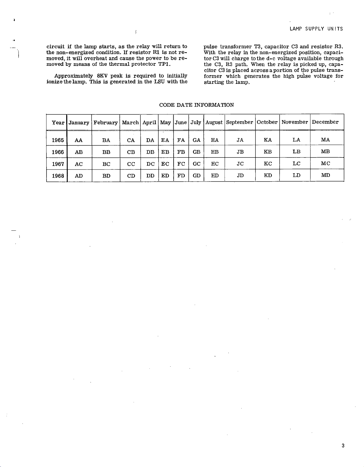
circuit
if
the
lamp
starts,
as
the
relay
will
return
to
the
non
-energized
condition.
If
resistor
R1
is
not
re-
moved,
it
will
overheat
and
cause
the
power
to
be
re-
moved
by
means
of
the
thermal
protector
TP1.
Approximately
8KV
peak
is
required
to
initially
ionize
the
lamp.
This
is
generated
in
the
LSU
with
the
pulse
transformer
T3,
capacitor
C3
and
resistor
R3.
With
the
relay
in
the
non
-energized
position,
capaci-
tor
C3
will
charge
to
the
d
-c
voltage
available
through
the
C3,
R3
path.
When
the
relay
is
picked
up,
capa-
citor
C3
is
placed
across
aportion
of
the
pulse
trans-
former
which
generates
the
high
pulse
voltage
for
starting
the
lamp.
CODE
DATE
INFORMATION
Year
January
February
March
April
May
June
July
August
September
October
November
December
1965
AA
BA
CA
DA
EA
FA
GA
HA
JA
KA
LA
MA
1966
AB
BB
CB
DB
EB
FB
GB
HB
JB
KB
LB
MB
1967
AC
BC
CC
DC
EC
FC
GC
HC
JC
KC
LC
MC
1968
AD
BD
CD
DD
ED
FD
GD
HD
JD
KD
LD
MD
3

SERVICE
INSTRUCTIONS
ELECT_RICAL
TEST
PROCEDURES
SPECIAL
TEST
EQUIPMENT
REQUIRED.
Accurate
testing
of
the
Lamp
Supply
Unit
requires
the
following
special
test
equipment,
as
well
as
the
commercially
available
test
equipment
listed
in
Table
II.
Complete
specifications
for
the
special
test
equip-
ment
are
illustrated
and
listed
in
Figures
1,
2
and
3
of
these
instructions.
These
units
are
not
available
from
Bell
&
Howell
and
must
be
assembled
according
to
the
specifications
illustrated.
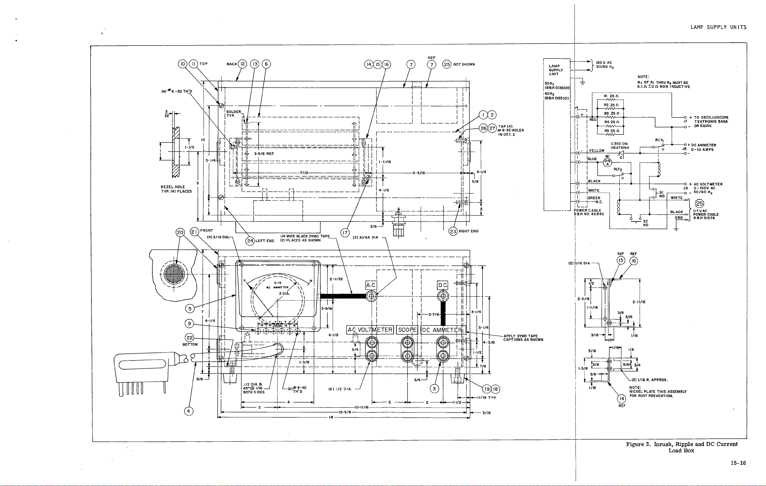
TABLE
I.
SPECIAL
TEST
EQUIPMENT
Description
Fig.
Ref.
B
&
H
Part
No.
Open
Circuit
Starting
1
S
-013000-1-F3
Voltage
Tester
Pulse
Voltage
Test
Box
for
LSU
2
S
-013000-1-F1
Inrush,
Ripple
and
D
-C
Current
Load
Box
3
S
-013000-1-F4
COMMERCIAL
TEST
EQUIPMENT
REQUIRED.
Table
II
lists
the
commercially
available
test
equip-
ment
required
for
performance
of
test
procedures
outlined
in
these
instructions.
TABLE
II
.
COMMERCIAL
TEST
EQUIPMENT
Test
Equipment
Recommended
Model
(Or
Equivalent)
Oscilloscope
Tektronix
Model
535A
Plug
-In
Unit
Tektronix
Model
53/54CA
10:1
Attennuator
Probe
Tektronix
Model
P6006
Variac
(Monitored)
General
Radio
Type
W20MT3A
(50/60
Hz)
Hi
-Pot
Tester
Associated
Research
Model
411
Thermocouple
Meter
Simpson
Model
388-3L
DC
Voltmeter
Simpson
Model
1327
(0-500
VDC)
DC
Ammeter
Simpson
Model
1327
(0-10
ADC)
TABLE
III.
TEST
LIMITS
Parameter
Input
Voltage
(See
*Note)
Limit
Testing
Conditions
Maximum
Minimum
Starting:
Open
Circuit
105
120
-
350
V
290
V
-
See
Fig.
1
Pulse
Voltage
105
120
—
12.0
KV
Total
(1200V
across
1
K
-ohm)
6.6
KV
Total
(660V
across
1
K
-ohm)
—
See
Fig.
2
Load
Inrush
Current
120
36
amps
(182V
Peak
across
5.1
ohm)
20
amps
(102V
Peak
across
5.1
ohm)
See
Fig.
3
Relay
Cycle
Time
120
44
Cycles
12
Cycles
See
Fig.
2
30
Seconds
30
Seconds
Running:
Output
Current
120
7.9
D.C.
7.4
D.C.
See
Fig.
3
Ripple
Current
120
2.4
A.P
P
(12.2V
P
-P
across
5.1
ohm)
—
See
Fig.
3
Input
Current
120
9.0
A.
AC
—
See
Fig.
3
*NOTE:
Use
50
-Hz
input
voltage
for
50
-Hz
LSU
(Part
No.
013300).
Use
60
-Hz
input
voltage
for
60
-Hz
LSU
(Part
No.
013310).
4
LAMP
SUPPLY
UNITS
WARNING
WHEN
THE
LAMP
SUPPLY
UNIT
IS
ENER-
GIZED,
THE
9000
-VOLT
STARTING
PULSE
IS
PRESENT.
EXTREME
CAUTION
MUST
BE
EXERCISED
WHEN
OPERATING
THE
POWER
SUPPLY
WHILE
NOT
CONNECTED
TO
A
PROJECTOR
OR
WHILE
THE
POWER
SUP-
PLY
COVER
IS
REMOVED,
IN
ORDER
TO
PREVENT
SEVERE
ELECTRICAL
SHOCK.
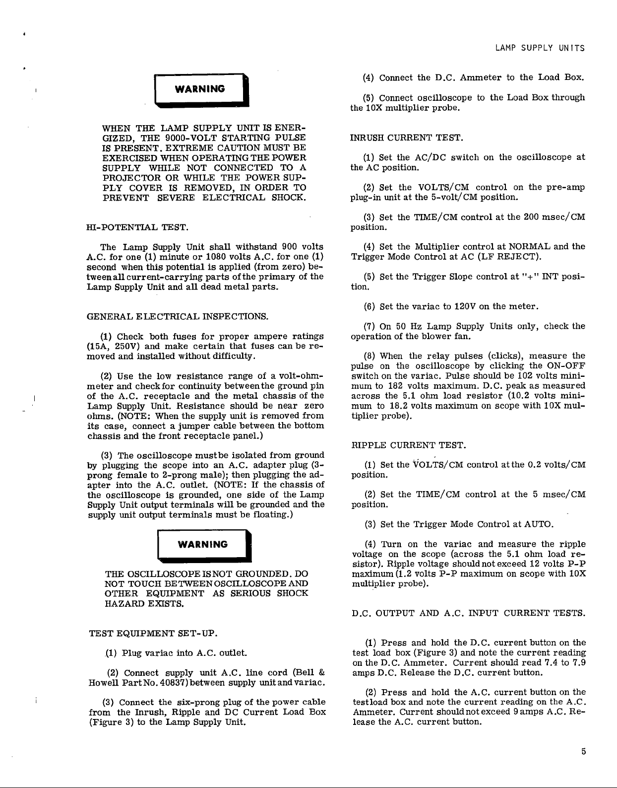
HI
-POTENTIAL
TEST.
The
Lamp
Supply
Unit
shall
withstand
900
volts
A.C.
for
one
(1)
minute
or
1080
volts
A.C.
for
one
(1)
second
when
this
potential
is
applied
(from
zero)
be-
tween
all
current
-carrying
parts
of
the
primary
of
the
Lamp
Supply
Unit
and
all
dead
metal
parts.
GENERAL
ELECTRICAL
INSPECTIONS.
(1)
Check
both
fuses
for
proper
ampere
ratings
(15A,
250V)
and
make
certain
that
fuses
can
be
re-
moved
and
installed
without
difficulty.
(2)
Use
the
low
resistance
range
of
a
volt
-ohm-
meter
and
check
for
continuity
between
the
ground
pin
of
the
A.C.
receptacle
and
the
metal
chassis
of
the
Lamp
Supply
Unit.
Resistance
should
be
near
zero
ohms.
(NOTE:
When
the
supply
unit
is
removed
from
its
case,
connect
a
juniper
cable
between
the
bottom
chassis
and
the
front
receptacle
panel.)
(3)
The
oscilloscope
mustbe
isolated
from
ground
by
plugging
the
scope
into
an
A.C.
adapter
plug
(3
-
prong
female
to
2
-prong
male);
then
plugging
the
ad-
apter
into
the
A.C.
outlet.
(NOTE:
If
the
chassis
of
the
oscilloscope
is
grounded,
one
side
of
the
Lamp
Supply
Unit
output
terminals
will
be
grounded
and
the
supply
unit
output
terminals
must
be
floating.)
WARNING
THE
OSCILLOSCOPE
ISNOT
GROUNDED.
DO
NOT
TOUCH
BE
TWEEN
OSCILLOSCOPE
AND
OTHER
EQUIPMENT
AS
SERIOUS
SHOCK
HAZARD
EXISTS.
TEST
EQUIPMENT
SET-UP.
(1)
Plug
variac
into
A.C.
outlet.
(2)
Connect
supply
unit
A.C.
line
cord
(Bell
&
Howell
Part
No.
4083'7)
between
supply
unit
and
variac.
(3)
Connect
the
six
-prong
plug
of
the
power
cable
from
the
Inrush,
Ripple
and
DC
Current
Load
Box
(Figure
3)
to
the
Lamp
Supply
Unit.
(4)
Connect
the
D.C.
Ammeter
to
the
Load
Box.
(5)
Connect
oscilloscope
to
the
Load
Box
through
the
10X
multiplier
probe.
INRUSH
CURRENT
TEST.
(1)
Set
the
AC/DC
switch
on
the
oscilloscope
at
the
AC
position.
(2)
Set
the
VOLTS/CM
control
on
the
pre
-amp
plug-in
unit
at
the
5-volt/CM
position.
(3)
Set
the
TIME/CM
control
at
the
200
msec/CM
position.
(4)
Set
the
Multiplier
control
at
NORMAL
and
the
Trigger
Mode
Control
at
AC
(LF
REJECT).
(5)
Set
the
Trigger
Slope
control
at
"+"
INT
posi-
tion.
(6)
Set
the
variac
to
120V
on
the
meter.
(7)
On
50
Hz
Lamp
Supply
Units
only,
check
the
operation
of
the
blower
fan.
(8)
When
the
relay
pulses
(clicks),
measure
the
pulse
on
the
oscilloscope
by
clicking
the
ON
-OFF
switch
on
the
variac.
Pulse
should
be
102
volts
mini-
mum
to
182
volts
maximum.
D.C.
peak
as
measured
across
the
5.1
ohm
load
resistor
(10.2
volts
mini-
mum
to
18.2
volts
maximum
on
scope
with
10X
mul-
tiplier
probe).
RIPPLE
CURRENT
TEST.
(1)
Set
the
VOLTS/CM
control
at
the
0.2
volts/CM
position.
(2)
Set
the
TIME/CM
control
at
the
5
msec/CM
position.
(3)
Set
the
Trigger
Mode
Control
at
AUTO.
(4)
Turn
on
the
variac
and
measure
the
ripple
voltage
on
the
scope
(across
the
5.1
ohm
load
re-
sistor).
Ripple
voltage
should
not
exceed
12
volts
P
-P
maximum
(1.2
volts
P
-P
maximum
on
scope
with
10X
multiplier
probe).
D.C.
OUTPUT
AND
A.C.
INPUT
CURRENT
TESTS.
(1)
Press
and
hold
the
D.C.
current
button
on
the
test
load
box
(Figure
3)
and
note
the
current
reading
on
the
D.C.
Ammeter.
Current
should
read
7.4
to
7.9
amps
D.C.
Release
the
D.C.
current
button.
(2)
Press
and
hold
the
A.C.
current
button
on
the
testload
box
and
note
the
current
reading
on
the
A.C.
Ammeter.
Current
should
not
exceed
9
amps
A
.C
.
Re-
lease
the
A.C.
current
button.
5

SERVICE
INSTRUCTIONS
PULSE
VOLTAGE
AND
RELAY
CYCLE
TIME
TESTS.
(1)
Connect
the
six
-prong
plug
of
the
power
cable
from
the
Pulse
Voltage
Test
Box
(Figure
2)
to
the
Lamp
Supply
Unit.
(2)
Connect
the
oscilloscope
to
the
test
box
through
the
10X
multiplier
probe.
(3)
Set
the
VOLTS/CM
control
at
the
20
volts/CM
position.
(4)
Set
the
TIME/CM
control
at
the
5
microsec-
ond/CM
position.
(5)
Set
the
Trigger
Mode
Control
at
AC
(LF
RE-
JECT)
and
the
Trigger
Slope
Control
at
"+"
INT.
(6)
Switch
the
variac
ON
and
adjust
the
Stability
and
Triggering
Level
controls
(per
manufacturer's
instruction
book)
to
obtain
a
single
pulse.
(7)
Adjust
the
Horizontal
Position
control
to
cen-
ter
the
pulse
on
the
face
of
the
CRT.
(8)
Adjust
the
variac
for
120
volts
A.C.
on
the
me-
ter
and
measure
the
peak
amplitude
of
the
starting
pulse.
The
pulse
should
not
be
greater
than
12,000
volts
(120
volts
on
scope
with
10X
multiplier
probe).
(9)
Using
the
sweep
second
hand
of
a
watch
or
clock,
count
the
number
of
pulses
in
a
30
-second
per-
iod.
There
should
be
between
12
and
44
pulses
in
a
30-
second
period.
(10)
Adjust
the
variac
for
105
volts
A.C.
on
the
meter
and
measure
the
peak
amplitude
of
the
start-
ing
pulse.
The
pulse
should
not
be
less
than
6,600
volts
peak
(66
volts
on
scope
with
10X
multiplier
probe).
OPEN
CIRCUIT
VOLTAGE
TEST.
(1)
Connect
the
six
-prong
plug
of
the
power
cable
from
the
Open
Circuit
Starting
Voltage
Tester
(Fig-
ure
1)
to
the
Lamp
Supply
Unit.
(2)
Switch
the
variac
ON
and
adjust
for
105
volts
on
the
A.C.
meter.
The
D.C.
output
voltage
should
be
greater
than
290
volts
D.C.
on
the
D.C.
meter.
(3)
Adjust
the
variac
for
120
volts
on
the
A.C.
me-
ter.
The
D.C.
output
voltage
should
be
less
than
350
volts
on
the
D.C.
meter.
6
LAMP
SUPPLY
UNITS
TROUBLE
SHOOTING
WARNING
WHEN
THE
LAMP
SUPPLY
UNIT
IS
ENER-
GIZED,
THE
9000
-VOLT
STARTING
PULSE
IS
PRESENT.
EXTREME
CAUTION
MUST
BE
EXERCISED
WHEN
OPERATING
THE
POWER
SUPPLY
WHILE
NOT
CONNECTED
TO
A
PROJECTOR
OR
WHILE
THE
POWER
SUP-
PLY
COVER
IS
REMOVED,
IN
ORDER
TO
PREVENT
SEVERE
ELECTRICAL
SHOCK.
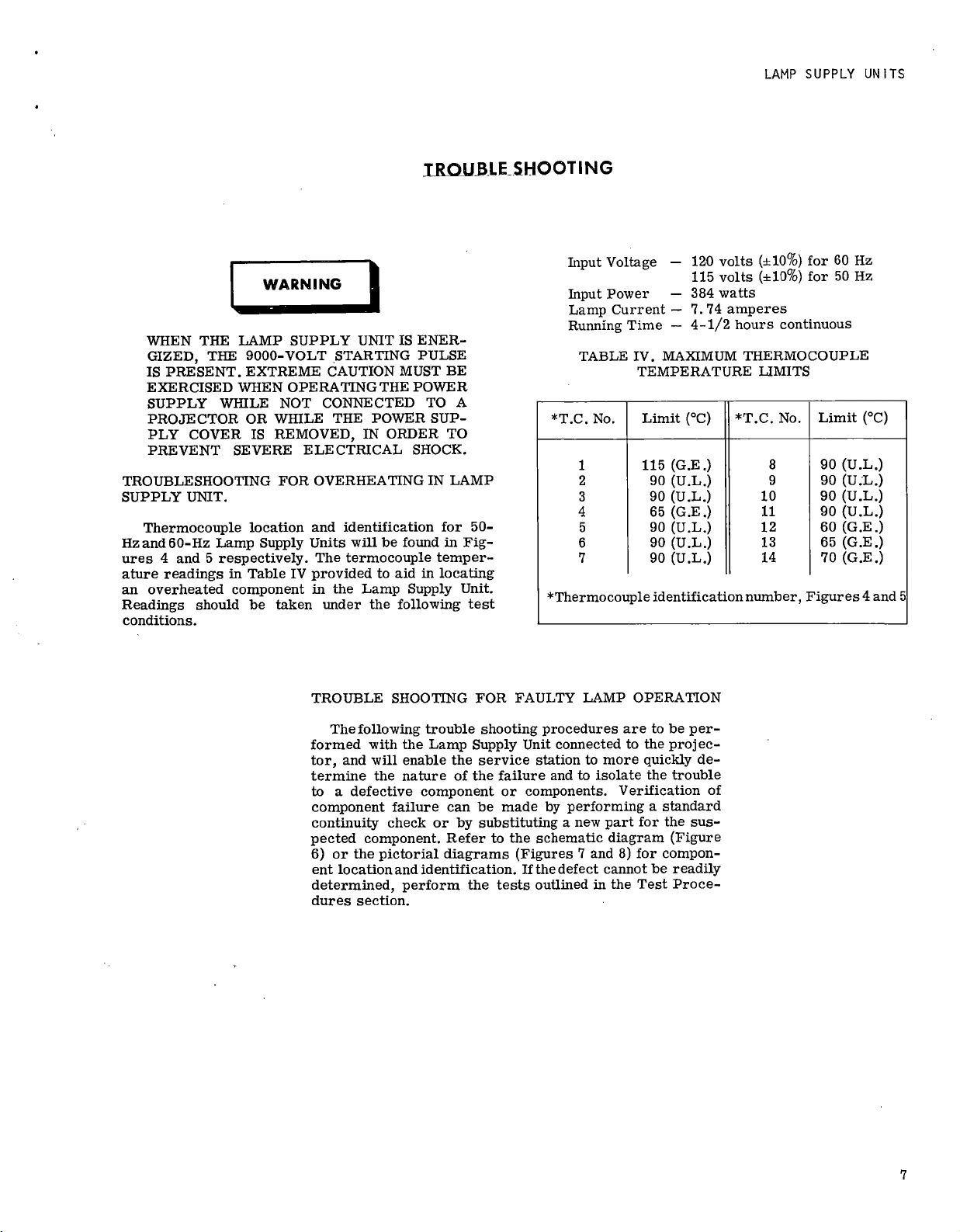
TROUBLESHOOTING
FOR
OVERHEATING
IN
LAMP
SUPPLY
UNIT.
Thermocouple
location
and
identification
for
50
-
Hz
and
60
-Hz
Lamp
Supply
Units
will
be
found
in
Fig-
ures
4
and
5
respectively.
The
termocouple
temper-
ature
readings
in
Table
IV
provided
to
aid
in
locating
an
overheated
component
in
the
Lamp
Supply
Unit.
Readings
should
be
taken
under
the
following
test
conditions.
Input
Voltage
—
Input
Power
—
Lamp
Current
—
Running
Time
—
120
volts
(±10%)
for
60
Hz
115
volts
(±10%)
for
50
Hz
384
watts
7.74
amperes
4-1/2
hours
continuous
TABLE
IV.
MAXIMUM
THERMOCOUPLE
TEMPERATURE
LIMITS
*T.C.
No.
Limit
(°C)
*T.C.
No.
Limit
(
°
C)
1
115
(G.E.)
8
90
(U.L.)
2
90
(U.L.)
9
90
(U.L.)
3
90
(U.L.)
10
90
(U.L.)
4
65
(G.E.)
11
90
(U.L.)
5
90
(U.L.)
12
60
(G.E.)
6
90
(U.L.)
13
65
(G.E.)
7
90
(U.L.)
14
70
(G.E.)
*Thermocouple
identification
number,
Figures
4
and
5
TROUBLE
SHOOTING
FOR
FAULTY
LAMP
OPERATION
The
following
trouble
shooting
procedures
are
to
be
per-
formed
with
the
Lamp
Supply
Unit
connected
to
the
proj
ec-
tor,
and
will
enable
the
service
station
to
more
quickly
de-
termine
the
nature
of
the
failure
and
to
isolate
the
trouble
to
a
defective
component
or
components.
Verification
of
component
failure
can
be
made
by
performing
a
standard
continuity
check
or
by
substituting
a
new
part
for
the
sus-
pected
component.
Refer
to
the
schematic
diagram
(Figure
6)
or
the
pictorial
diagrams
(Figures
7
and
8)
for
compon-
ent
location
and
identification.
If
the
defect
cannot
be
readily
determined,
perform
the
tests
outlined
in
the
Test
Proce-
dures
section.
7
SERVICE
INSTRUCTIONS
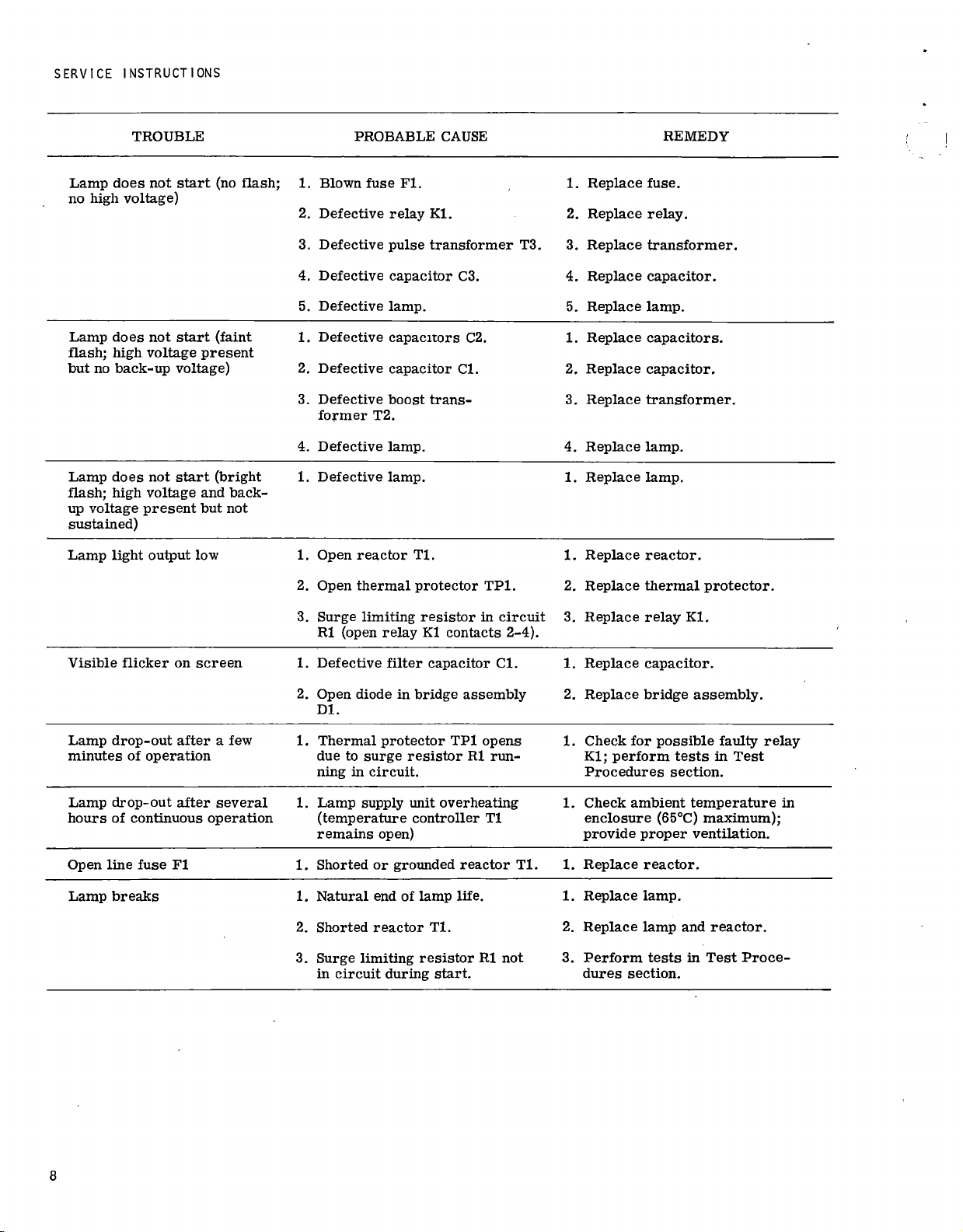
TROUBLE
PROBABLE
CAUSE
REMEDY
Lamp
does
not
start
(no
flash;
no
high
voltage)
1.
Blown
fuse
Fl.
2.
Defective
relay
Ki.
3.
Defective
pulse
transformer
4.
Defective
capacitor
C3.
5.
Defective
lamp.
1.
Replace
fuse.
2.
Replace
relay.
T3.
3.
Replace
transformer.
4.
Replace
capacitor.
5.
Replace
lamp.
Lamp
does
not
start
(faint
flash;
high
voltage
present
but
no
back-up
voltage)
1.
Defective
capacitors
C2.
2.
Defective
capacitor
Cl.
3.
Defective
boost
trans-
former
T2.
4.
Defective
lamp.
1.
Replace
capacitors.
2.
Replace
capacitor.
3.
Replace
transformer.
4.
Replace
lamp.
Lamp
does
not
start
(bright
flash;
high
voltage
and
back-
up
voltage
present
but
not
sustained)
1.
Defective
lamp.
1.
Replace
lamp.
Lamp
light
output
low
1.
Open
reactor
Tl.
2.
Open
thermal
protector
TP1.
3.
Surge
limiting
resistor
in
circuit
R1
(open
relay
Ki
contacts
2-4).
1.
Replace
reactor.
2.
Replace
thermal
protector.
3.
Replace
relay
Ki.
Visible
flicker
on
screen
1.
Defective
filter
capacitor
Cl.
2.
Open
diode
in
bridge
assembly
Dl.
1.
Replace
capacitor.
2.
Replace
bridge
assembly.
Lamp
drop
-out
after
a
few
minutes
of
operation
1.
Thermal
protector
TP1
opens
due
to
surge
resistor
R1
run-
ning
in
circuit.
1.
Check
for
possible
faulty
relay
Kl;
perform
tests
in
Test
Procedures
section.
Lamp
drop
-out
after
several
hours
of
continuous
operation
1.
Lamp
supply
unit
overheating
(temperature
controller
Ti
remains
open)
1.
Check
ambient
temperature
in
enclosure
(65°C)
maximum);
provide
proper
ventilation.
Open
line
fuse
Fl
1.
Shorted
or
grounded
reactor
Tl.
1.
Replace
reactor.
Lamp
breaks
1.
Natural
end
of
lamp
life.
2.
Shorted
reactor
Ti.
3.
Surge
limiting
resistor
R1
not
in
circuit
during
start.
1.
Replace
lamp.
2.
Replace
lamp
and
reactor.
3.
Perform
tests
in
Test
Proce-
dures
section.
8

LAMP
SUPPLY
UNITS
TROUBLE
SHOOTING
WITH
TEST
EQUIPMENT.
If
the
results
of
tests
performed
in
the
Electrical
Test
Procedures
section
fail
to
meet
noted
specification
require-
ments,
use
the
following
troubleshooting
guide
to
isolate
and
correct
the
trouble.
Refer
to
the
schematic
wiring
dia-
gram
(Figure
6)
and
the
pictorial
diagrams
(Figures
7
and
8)
for
component
location
and
identification.
WARNING
WHEN
THE
LAMP
SUPPLY
UNIT
IS
ENER-
GIZED,
THE
9000
-VOLT
STARTING
PULSE
IS
PRESENT.
EXTREME
CAUTION
MUST
BE
EXERCISED
WHEN
OPERATING
THE
POWER
SUPPLY
WHILE
NOT
CONNECTED
TO
A
PROJECTOR
OR
WHILE
THE
POWER
SUP-
PLY
COVER
IS
REMOVED,
IN
ORDER
TO
PREVENT
SEVERE
ELECTRICAL
SHOCK.
TROUBLE
PROBABLE
CAUSE
REMEDY
(TROUBLES
DURING
STARTING)
No
open
circuit
voltage
(see
1.
Blown
fuse
Fl.
1.
Replace
fuse.
Figure
1)
2.
Open
connection.
3.
Shorted
boost
transformer
T2.
4.
Shorted
rectifier
bridge
Dl.
2.
Check
circuit
and
correct
condition.
3.
Replace
transformer.
4.
Replace
rectifier
bridge.
Low
open
circuit
voltage
(see
1.
Defective
voltage
doubler
Figure
1
capacitor
C2.
2.
Open
rectifier
bridge
Dl.
3.
Defective
boost
transformer
T2.
4.
Leaky
filter
capacitor
Cl.
5.
Open
leads.
1.
Replace
capacitor.
2.
Replace
rectifier
bridge.
3.
Replace
transformer.
4.
Replace
capacitor.
5.
Perform
continuity
check;
correct
condition.
Variable
open
circuit
voltage
(see
Figure
1)
1.
Open
surge
resistor
R1
(varies
with
relay
cycling).
1.
Replace
resistor.
No
pulse
voltage
(see
Figure
2)
1.
Defective
pulse
transformer
T3.
2.
Relay
K1
not
cycling
(bad
contacts).
1.
Replace
transformer.
2.
Clean
contacts
or
replace
relay.
3.
Open
connection
or
short
circuit.
3.
Check
circuit
and
correct
condition.
4.
Open
surge
resistor
Rl.
4.
Replace
resistor.
5.
Open
or
shorted
filter
capacitor
5.
Replace
capacitor.
Cl.
9
SERVICE
INSTRUCTIONS
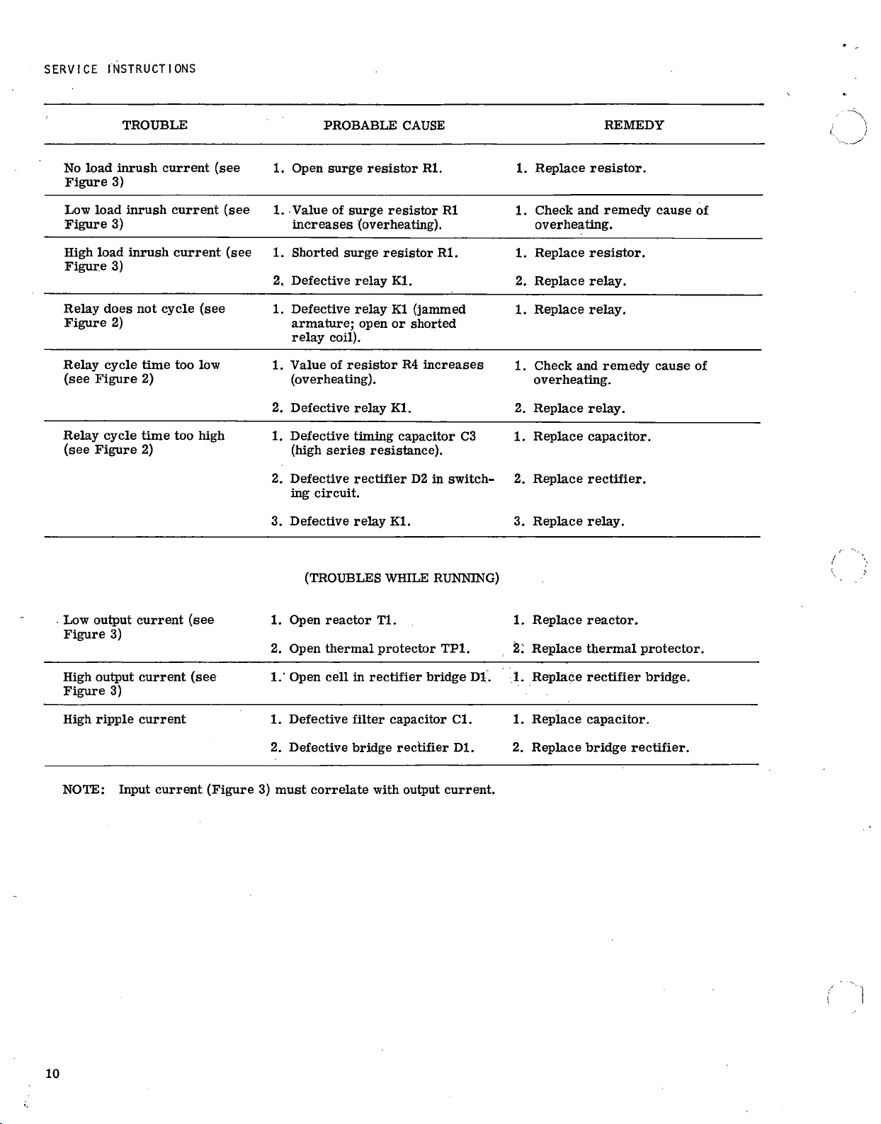
TROUBLE
PROBABLE
CAUSE
REMEDY
No
load
inrush
current
(see
Figure
3)
1.
Open
surge
resistor
Rl.
1.
Replace
resistor.
Low
load
inrush
current
(see
1.
Value
of
surge
resistor
R1
Figure
3)
increases
(overheating).
1.
Check
and
remedy
cause
of
overheating.
High
load
inrush
current
(see
Figure
3)
1.
Shorted
surge
resistor
Rl.
2.
Defective
relay
Kl.
1.
Replace
resistor.
2.
Replace
relay.
Relay
does
not
cycle
(see
Figure
2)
1.
Defective
relay
K1
(jammed
armature;
open
or
shorted
relay
coil).
1.
Replace
relay.
Relay
cycle
time
too
low
(see
Figure
2)
1.
Value
of
resistor
R4
increases
(overheating).
2.
Defective
relay
Kl.
1.
Check
and
remedy
cause
of
overheating.
2.
Replace
relay.
Relay
cycle
time
too
high
(see
Figure
2)
1.
Defective
timing
capacitor
C3
(high
series
resistance).
2.
Defective
rectifier
D2
in
switch-
ing
circuit.
3.
Defective
relay
Kl.
1.
Replace
capacitor.
2.
Replace
rectifier.
3.
Replace
relay.
Low
output
current
(see
Figure
3)
(TROUBLES
WHILE
RUNNING)
1.
Open
reactor
Tl.
2.
Open
thermal
protector
TP1.
1.
Replace
reactor.
2:
Replace
thermal
protector.
High
output
current
(see
Figure
3)
1.'
Open
cell
in
rectifier
bridge
Di.
1.
Replace
rectifier
bridge.
High
ripple
current
1.
Defective
filter
capacitor
Cl.
2.
Defective
bridge
rectifier
Dl.
1.
Replace
capacitor.
2.
Replace
bridge
rectifier.
NOTE:
Input
current
(Figure
3)
must
correlate
with
output
current.
10

LIST
OF
MATERIAL
REQUIRED
FOR
OPEN
CIRCUIT
STARTING
VOLTAGE
TESTER
(FIGURE
1)
Detail
No.
Description
Qty.
Req'd.
Part
Number
1
CAPACITOR,
5.0
mfd,
600
vdc
(C1)
1
G.E.
Type
23F1214
or
2
1/32
by
2
by
5-21/32
inch
aluminum
1
Allied
No.
43D0084
3
SCREW,
Round
hd
machine,
8-32NC
by
3/8
inch
2
4
BINDING
POST,
Dual
(J2,
J3)
2
H.H.
Smith
Type
269RB
or
Allied
No.
47D1324
5
6
TERMINAL,
Insulated
stand
off
SCREW,
Socket
hd
machine,
8-32NC
by
1/2
inch
4
16
Grayhill
Type
18-2
or
Allied
No.
47D5291
7
FOOT,
Rubber
4
8
SCREW,
Socket
hd
machine,
1/4-20NC
by
1/2
inch
4
9
PLEXIGLAS,
Clear,
3/8
by
5-1/4
by
8
inches
1
10
PLEXIGLAS,
Clear,
3/8
by
4
by
5-1/4
inches
2
11
PLEXIGLAS,
Clear,
3/8
by
4-3/4
by
8
inches
1
12
PLEXIGLAS,
Clear,
3/8
by
5-1/4
by
8
inches
1
13
PLEXIGLAS,
Clear,
3/8
by
4-3/4
by
8
inches
1
14
CABLE
ASSEMBLY
(J1)
1
Bell
&
Howell
No.
40845
15
LUG,
Solder
(any
suitable
type)
2

LAMP
SUPPLY
UNITS
2
DRILL
a
TAP
NO.8-32
THD
(2)
I
2-19/32
5-I/4
4-1/2
1-7/8
3/8
3/16—+
5-1/4
8
7
5/8
(4)
1/2
DIA
---
v2
3/16-
1/2
DIA
a
1/16)45°
BOTH
SIDES
6
7
_
16
7
16
647
7
1
7
8
-
1
7
4
‘•
2
II
II
7-5/8
2
4
AC
VOLTS
VOLTS
I
(4)3/8
R
AD)
3/8
TYP
z
CD
3/4
1
7/8
1-1/2
11/16
TYP-
0
-1
1-
0
-
7
8
DRILL
a
TAP
NO.4-40
THD
(6)
15
3/16
2-5/32
-1/64
1-5/16
2
REF
(2)
11/64
DIA.
APPLY
DYMOTAPE
CAPTIONS
AS
SHOWN
LAMP
SUPPLY
UNIT
50
Hz (B&H
013300)
60
Hz (B&H
013310)
4-
J-
1
120
VAC
50/60
Hz
JI
<<
+
RED
-Fi
CI
k
-
YELLOW
I
I
600V.
DC
J2
DC
VOLTMETER
0-400V
5.0
MFD
0
I,
BLUE_ORI
ORN
<lc
•
0+
%
I
BLACK
,j3
AC
VOLTMETER
0-150V
<
I
i<
WHITE
0
50/60Hz
i
<1<
GREEN
L
-
CABLE
ASSY
B
a
H
NO.40845
12
o+
I
3/4
,.''V.,,..
11/16
co
Figure 1.
Open
Circuit Starting
Voltage
Tester
11-12

LIST
OF
MATERIAL
REQUIRED
FOR
PULSE
VOLTAGE
TEST
BOX
(FIGURE
2)
Detail
No.
Description
Qty.
Req'd.
Part
Number
1
BINDING
POST,
Dual
(J1,
J2)
2
H.H.
Smith
Type
269RB
or
Allied
No.
47D1324
3
CABLE
ASSEMBLY
(J4)
1
Bell
&
Howell
No.
40845
4
BUSHING,
Insulated,
thru-panel
(TH1,
2
and
3)
3
E.F.
Johnson
Type
135-50
or
Allied
No.
46Z217
5
Insulator,
Cone,
Steatite
(TH4)
9
E.F.
Johnson
Type
135-501
or
Newark
No.
37F064
6
RESISTOR,
Non
-inductive,
1K,
5W
±5%
(R1
thru
R10)
10
Sprague
Type
453E
or
7
SCREW,
Socket
hd
machine,
10-32
by
1
inch
18
Allied
No.
25Z925C
8
PLEXIGLAS,
Clear,
3/8
by
8
by
10
-inches
1
9
PLEXIGLAS,
Clear,
3/8
by
8
by
10
-inches
1
10
PLEXIGLAS,
Clear,
3/8
by
4-1/4
by
10
inches
1
11
PLEXIGLAS,
Clear,
3/8
by
4-1/4
by
10
inches
1
12
PLEXIGLAS,
Clear,
3/8
by
4-1/4
by
7-1/4
inches
1
13
PLEXIGLAS,
Clear,
3/8
by
4-1/4
by
7-1/4
inches
1
14
PLEXIGLAS,
Clear,
3/8
by
4-1/4
by
9-1/4
inches
1
15
GROMMET,
Rubber,
1/2
inch
I.D.
1
16
BEZEL,
Ventilating,
1
-inch
diameter
4
17
FOOT,
Rubber
4
18
SCREW,
Socket
hd
machine,
1/4-20
by
1/2
inch
4
LAMP
SUPPLY
UNITS
10
3
I
DIA
16
REF
I
DIA
1/16
2
DIA
6
4
5/8
TYP
5/8
12
10
16
1-3/8
z
0
-0
/
4-5/8
7
REF
14
,--
,/-
.
-
T A
i-
---
.1-
--i
+ -
-I-
+
--
4--
1-
7---
---
I
,
--=''''
4-
-/
--1-_
-_7-*,_-
\
\II
-r
\
1
k
4-
\--(Y
4-
I
\ I I
I
I
l
i
I
/
1
\
I
...-
..---
,
I
__
)
I,
('
I
)\,
I
`,_
)
1
-\---U
-4
H/
-
_,
__
_
_
_
_
/
__
____>
--
-7
i
--
---
>(....
_/
4
.
k-
z
- -
1
-
1
-
- -
--
__J__,
_,
)
J
---,-7
-
--.7,
--
-.
........
i,
'
A
..,-
-,--
:----
---)
17
18
VOLTS
SCOP4
1-7/8
0
I-1/2
0
0
0 -
1-3/4
I
-I/¢
<
APPLY
DYMOTAPE
-
CAPTIONS
AS
SHOWN
0
REF
7
1/8
1-3/
TYP
2-1/2
TYP
1/2
(2
PLACES)
3/4
3/8
R
3/16
TYP
13
LAMP
SUPPLY
UNIT
50
Hz
(Bali
.
N0.0B300)
60
Hz
(Ba
H
NO.013310)
120
VAC
50/60H
1
J4
I
RED
+
))
ORANGE
R7
R6
R5
R9
R4
RIO
R3
•
R2
•
IK
5W
5%
RI
R8
YELLOW
-
I,
BLACK
I
/
I
WHITE
>
I
>
GREEN
31/8
1
1/2—w-
0
-1
1/2
3
L
_______
Ba
H
CABLE
ASSY
NO.40845
9
1/
4
1
I
1/2-
01,4
---I 1/24."•-1-1/2-1.
1-3/8
-I-I/2
(3)1/2
DR.
JI
TO
SCOPE
(TEKTRONIX
•
MODEL
543A
OR
EQUIV.)
0
J2
TO
A.C
VOLTMETER
0
0-150
VAC
60
OR
50
H
z
4-1/4
0
PLEXIGLASS
DETAIL
(9)11/64
DR.
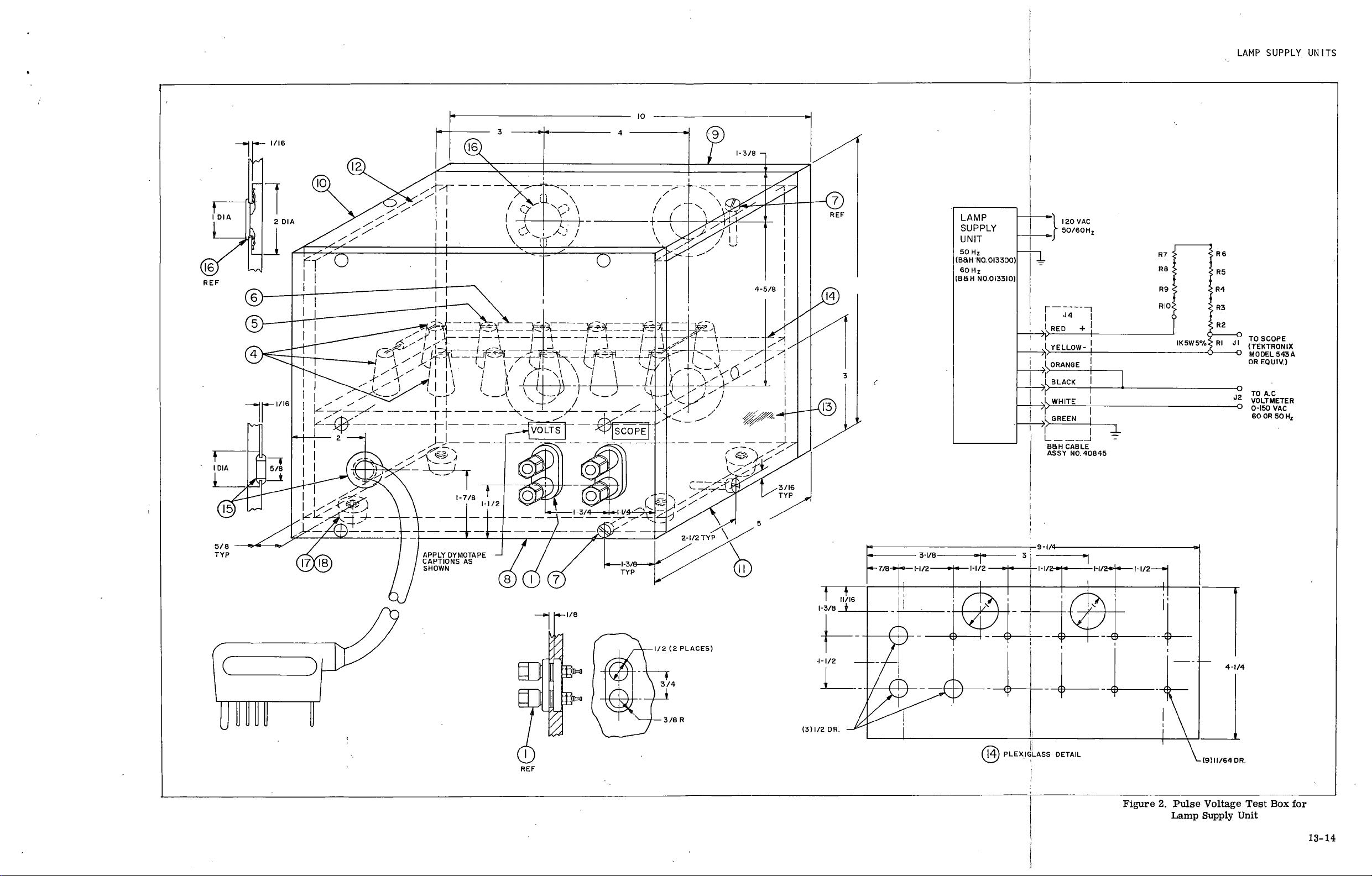
Figure
2.
Pulse
Voltage
Test
Box
for
Lamp
Supply
Unit
13-14
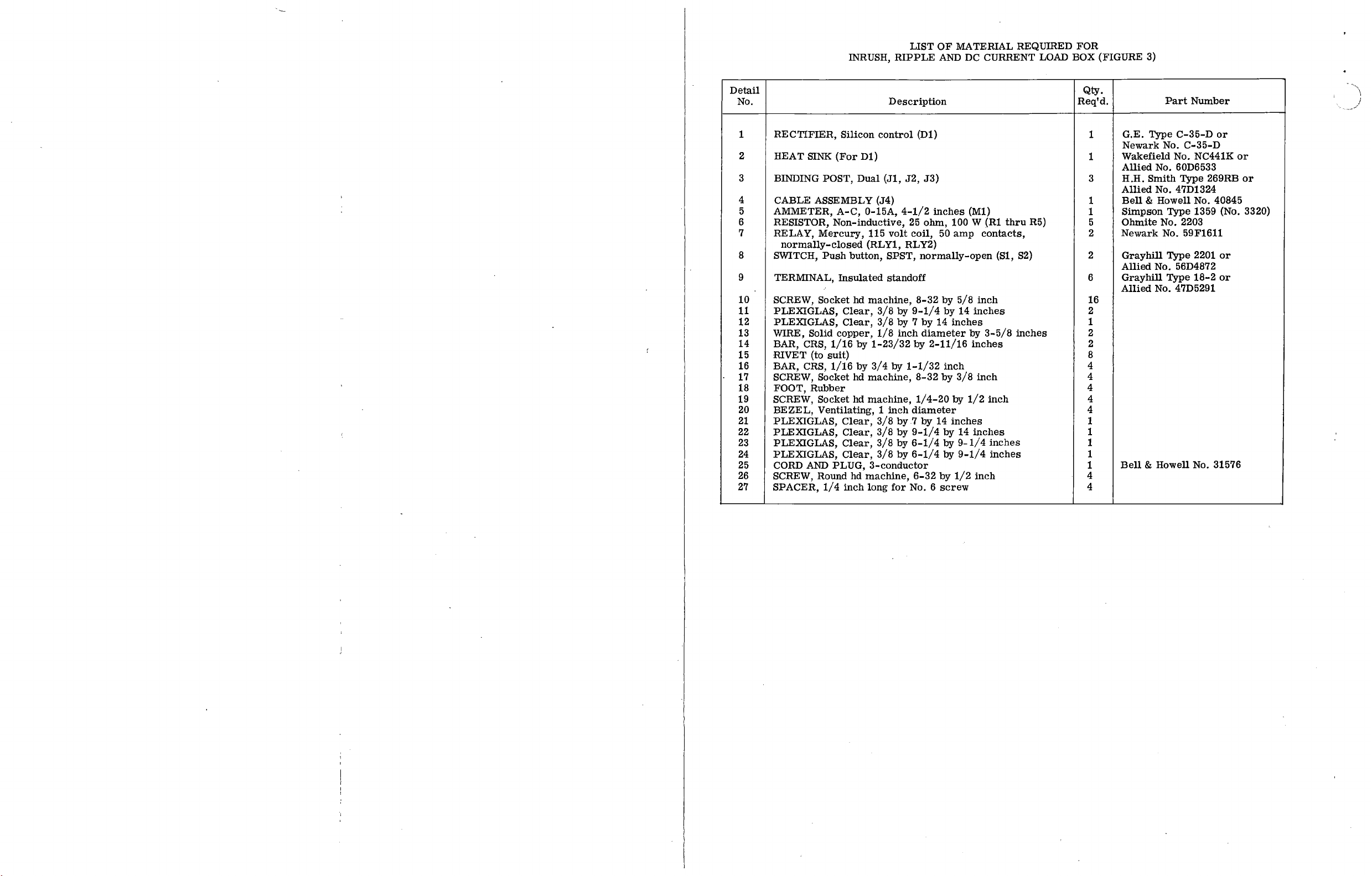
LIST
OF
MATERIAL
REQUIRED
FOR
INRUSH,
RIPPLE
AND
DC
CURRENT
LOAD
BOX
(FIGURE
3)
Detail
No.
Description
Qty.
Req'd.
Part
Number
1
RECTIFIER,
Silicon
control
(D1)
1
G.E.
Type
C
-35-D
or
Newark
No.
C
-35-D
2
HEAT
SINK
(For
D1)
1
Wakefield
No.
NC441K
or
Allied
No.
60D6533
3
BINDING
POST,
Dual
(J1,
J2,
J3)
3
H.H.
Smith
Type
269RB
or
Allied
No.
47D1324
4
CABLE
ASSEMBLY
(.14)
1
Bell
&
Howell
No.
40845
5
AMMETER,
A
-C,
0-15A,
4-1/2
inches
(M1)
1
Simpson
Type
1359
(No.
3320)
6
RESISTOR,
Non
-inductive,
25
ohm,
100
W
(R1
thru
R5)
5
Ohmite
No.
2203
7
RELAY,
Mercury,
115
volt
coil,
50
amp
contacts,
normally
-closed
(RLY1,
RLY2)
2
Newark
No.
59F1611
8
SWITCH,
Push
button,
SPST,
normally
-open
(S1,
S2)
2
Grayhill
Type
2201
or
Allied
No.
56D4872
9
TERMINAL,
Insulated
standoff
6
Grayhill
Type
18-2
or
Allied
No.
47D5291
10
SCREW,
Socket
hd
machine,
8-32
by
5/8
inch
16
11
PLEXIGLAS,
Clear,
3/8
by
9-1/4
by
14
inches
2
12
PLEXIGLAS,
Clear,
3/8
by
7
by
14
inches
1
13
WIRE,
Solid
copper,
1/8
inch
diameter
by
3-5/8
inches
2
14
BAR,
CRS,
1/16
by
1-23/32
by
2-11/16
inches
2
15
RIVET
(to
suit)
8
16
BAR,
CRS,
1/16
by
3/4
by
1-1/32
inch
4
•
17
SCREW,
Socket
hd
machine,
8-32
by
3/8
inch
4
18
FOOT,
Rubber
4
19
SCREW,
Socket
hd
machine,
1/4-20
by
1/2
inch
4
20
BEZEL,
Ventilating,
1
inch
diameter
4
21
PLEXIGLAS,
Clear,
3/8
by
7
by
14
inches
1
22
PLEXIGLAS,
Clear,
3/8
by
9-1/4
by
14
inches
1
23
PLEXIGLAS,
Clear,
3/8
by
6-1/4
by
9-1/4
inches
1
24
PLEXIGLAS,
Clear,
3/8
by
6-1/4
by
9-1/4
inches
1
25
CORD
AND
PLUG,
3
-conductor
1
Bell
&
Howell
No.
31576
26
SCREW,
Round
hd
machine,
6-32
by
1/2
inch
4
2'7
SPACER,
1/4
inch
long
for
No.
6
screw
4
LAMP
SUPPLY
UNITS
REF
0
(4)
*
6
-32
TH
U
D
3
32
II
I-1/2
TOP
BACK
14
15 16
C)
NOT
SHOWN
10
BEZEL
HOLE
TYP.
(4)
PLACES
20
I
SOLDER
TYP.
-A-
lt
5
1/4
4
'.
1
I
1
--
4
I
L
REF
4-1/8
5
5/16
I
7
26
I
I
3/8
21
FRONT
(4)3/16
DIA.
24
1/4
WIDE
BLACK
DYMO
TAPE
LEFT
END
(2)
PLACES
AS
SHOWN
3/8
(2)
31/64
DIA
I
I
RIGHT
END
(i
)
22
BOTTOM
4-1/4
..---
----
---..."-..
./r
. I
0-15
\
AC
AMMETER
\\
3
DIA.
\
1
\
1
1r
7 7
.
1
6"
:
163r37:
16
"
16
b.(
• (
(0)
•
—
I
I
1-3/8
2-1/32
3-9/16
4-1/8
A.C.
D.C.
AC
VOLTMETER
c.‘
3/4
I
SCOPE
(0)
•
7/8
./
- 7 - 7 -
t
II
I
II
DC
AM
ET
I
2
3-1/4
5
1/4
I-1/2
27
4-3/8
3/8
1/2
DIA
8
45'
1/16
BOTH
S
IDES
2
)0
4
-
40
TH'D
14
10
11/16
3/4
2
3
1
1
1/2
7/8
19
TAP
(4)
#
6-32
HOLES
IN
DET.
2
18
11/16
TYP.
3/16
APPLY
DYMO
TAPE
CAPTIONS
AS
SHOWN
LAMP
SUPPLY
UNIT
50Hz (B&H
013300)
60Hz
(BEM
013310)
1
120
V.
AC
50/60
Hz NOTE
Rt
OF
RI
THRU
Rs
MUST
BE
5.1
IL
±0
fl
NON
INDUCTIVE
RI
25
ft
R2
25
ft
R3
25
0
RED
R4
2511
R5
25
0
C350
ON
YELLOW
HEATSINK
J1
R
Ls('
+
TO
OSCILLOSCOPE
TEKTRONIX
543A
OR
EQUIV.
+
DC
AMMETER
0
J
2
0-10
AMPS
BLUE
MI
DI
0-15
A
RLY2
BLACK
__i(
WHITE
_(
[
<
GREEN
N.C.
POWER
CABLE
B&H
NO.40845
(2)
1/16
DIA
•
+
AC
VOLTMETER
J3
0-150V
AC
SI
•
50/60
Hz NO
WHITE
S2
NO
REF REF
15
16
I
1,2
3/8
3/16
2-11/16
3/16
3/16
1
3/8
1-3/8
3/8
14
REF
(2)
1/16
R.
APPROX.
BLACK
117
VAC
POWER
CABLE
GRN
B&H
31576
NOTE:
NICKEL
PLATE
THIS
ASSEMBLY
FOR
RUST
PREVENTION.
Figure
3.
Inrush,
Ripple
and
DC
Current
Load
Box
15-16

LAMP
SUPPLY
UNITS
THERMOCOUPLE
IDENTIFICATION
(See
Figures
4
and
5)
Item
No.
Description
1
CENTER
—
Bridge
Rectifier
Case
D1
2
COIL
—
A.C.
Reactor
T1
3
CORE
—
A.C.
Reactor
Ti
4
CASE
—
Filter
Capacitor
C1
5
COIL
-
Pulse
Transformer
T3
6
BRACKET
—
Pulse
Transformer
T3
7
COIL
—
Pulse
Transformer
T3
8
COIL
-
Boost
Transformer
T2
9
CORE
—
Boost
Transformer
T2
10
COIL
—
A.C.
Reactor
T1
11
CORE
—
A.C.
Reactor
T1
12
EXPOSED
END
—
Voltage
Doubler
Capacitor
C2
13
AMBIENT
AIR
(Inside
Enclosure)
14
CASE
—
"Klixon"
Thermal
Protector
TP1
-
n
8
-
6Th
m
)
®
l0
c)
-4
O
C)
C)
(11
1
O
C)
C
I
1
-
o
;—
Figure
4.
Thermocouple
Location
and
Identification
for
50
Hz
Unit,
Part
No.
013300
2
C)
O
C)
n
I
di
9
III
I
14
8
0
9
e
10
0
13
e
0
0
O
2
5
-
4
0
0
C)
UI
C)
CM
L
O
1
O
0
C)
cn
0
Figure
5.
Thermocouple
Location
and
Identification
for
60
Hz
Unit,
Part
No.
013310
17-18
This manual suits for next models
1
Table of contents
Popular Projector Accessories manuals by other brands

New Star
New Star Neomounts BEAMER-C350BLACK instruction manual

Celexon
Celexon Professional Plus operating instructions

Sharp
Sharp AN-PH80CW installation manual

Barco
Barco ClickShare Present C Series installation manual

ZeeVee
ZeeVee ZVconnect user manual

Strong International
Strong International X-90 instruction manual


