Strong International X-90 User manual
X-90
Xenon Projection Console
Type 31000, 31002
Rev. 6/99
STRONG INTERNATIONAL
a division of Ballantyne of Omaha, Inc.
4350 McKinley Street
Omaha, Nebraska 68112 USA
Tel 402/453-4444 • Fax 402/453-7238


PREFACE
THE STRONG X-90 is a projection console using a horizontally mounted xenon bulb as the
light source. The reflector is an 11 inch deep ellipse type designed to operate at 25-3/4 inches from the film
plane. The standard reflector is dichroic (“cold”) coated to reduce heat at the film plane and prolong bulb life.
THE CONSOLE LAMPHOUSE is designed to incorporate xenon bulbs ranging from 1000 to
2500 watts. The standard switching xenon power supply is adjustable to operate these wattages throughout
their current ranges. Bulb Adapter Kit No. 31934 is supplied with each X-90 console, and will accommodate all
bulbs approved for used in the X-90.
TWO BULB SEAL BLOWERS are wired to the lamphouse control circuit to maintain the
bulb seals at a safe operating temperature. An air vane switch, located at the rear blower outlet, will interrupt
lamphouse operation in the event of a main blower failure, or if the main blower is not moving adequate air. The
blower motors are protected by a circuit breaker on the xenon power supply.
INTERLOCK SWITCHES on both the rear and operator side lamphouse access doors prevent
operation of the lamphouse if either door is opened. These switches insure operator safety and must not be
bypassed. The off-operator side door may be opened during operation to permit adjusting the xenon power
supply. Key locks on all doors assure access to authorized personnel only.
THE STANDARD ANALOG INSTRUMENT PANEL includes an elapsed time meter to record
the number of hours the bulb has operated. These hours should be recorded on the XENON BULB RECORD
on the inside back cover of this manual in the event of a warranty adjustment. The ammeter indicates the
operating current of the bulb; see the warranty information packed with the bulb to determine the correct current
setting for the bulb in use. Pressing the VOLTAGE switch will change the meter to display the DC voltage at the
arc. Volts times amperes will indicate exact wattage.
AN OPTIONAL DIGITAL INSTRUMENT PANEL employs a backlit LCD screen which
continuously displays the bulb current (amperes), arc voltage, operating wattage, and elapsed hours. The Bulb
Hours display (BLB) can be re-set upon installation of a new bulb, while the actual elapsed hours of the X-90
console are accumulated by the Total Hour (HR) display. To establish and maintain an accurate history of
xenon bulb usage, the Total Hour (HR) figures should be entered on the Xenon Bulb Record.
A POWER DISTRIBUTION CENTER is standard on the X-90. The input power require-
ment is a four-wire, three phase AC line, voltage as specified on the equipment Data Plate. An adequate earth
ground is also required. See the INSTALLATION INSTRUCTIONS following.
ALL BRANCH CIRCUITS are individually protected by means of circuit breakers wired to
the distribution panel. A ten ampere, 115 V.AC feed for the lamphouse exhaust blower is provided, and includes
an interlock circuit to disable lamphouse operation if the exhaust blower is not energized. A MASTER contactor
energizes all branch circuits simultaneously.
X90/001

Distribution
Center
Lamphouse
Access Door
Sound Rack
Pivot Rod
Key Lock
Automation
Compartment
Lamphouse
Control Panel Exhaust Stack
Arc Viewing Port
Nose Cone
Douser Handle
Bulb Focus Knob
Soundhead
Mounting Arm
Adjusting
Screws
Convenience
Outlet
STRONG X-90 CONSOLE
X90/002

INSTALLATION
INSPECT THE SHIPMENT immediately on arrival and report any damage to the freight
carrier. It is the responsibility of the consignee, not the shipper, to file these claims.
MOVE THE CONSOLE as close as possible to its installed position in the booth before
removing it from the shipping pallet.
WHEN ORDERED less the pre-wire option, the console can be disassembled to accommodate
narrow doorways and passages. The xenon power supply may be disconnected and dismounted to further
reduce weight. Current models feature twistlock connectors on both AC input and lamphouse outputs.
TO DISASSEMBLE THE CONSOLE, remove the (2) hex head screws from the tilt adjust
locks at the rear of the console. Both screws are accessible through the rear door. Remove (1) snap ring from
the end of the pivot rod at the front upright portion of the console, and slide the pivot rod out. The upright
portion of the console can then be lifted from the base.
IF REMOVING the xenon power supply from an earlier mofel X-90, note carefully the wire
numbers and/or colors to enable correct re-connection. The output side of the power supply contains the DC
leads, positive (red) and negative (black), (5) numbered control leads, and a ground lead (green). The input side
includes (3) AC leads (L1, L2, L3), and a ground lead (green). Observe correct polarity and control wire
numbering when replacing these leads.
REASSEMBLE THE CONSOLE by reversing the above sequence. The angle of tilt will be
set at a subsequent point of the installation.
ASSEMBLE THE FOUR LEVELING FEET to the base of the console before or when remov-
ing the console from the shipping pallet. Position the console in front of the projection port as required.
THE AC SUPPLY to the X-90 must be a four-wire three phase line, plus ground, installed in
conformance to local codes by a qualified electrician. Voltage requirement is stamped on the equipment Data
Plate. These AC connections are made to the bottom terminals (as marked) of terminal board TB1, located
behind the rear access door and below the master contactor enclosure. Wire connections are as follow:
AC Phase TB1-1,2,3
Ground TB1-4
AC Neutral TB1-5
WHEN ORDERED with Strong automation, all automation terminals are factory prewired.
See the installation manual for the correct automation system for the interconnections to house functions.
X90/003

CONSOLES SHIPPED without automation controllers can be wired for automatic or remote
lamphouse ignition by connecting a sustained 5 ampere dry contact between terminals 3 & 6 in the xenon power
supply. These terminals are located behind the access panel above the data plate on the power supply cabinet.
DO NOT apply voltage to these terminals.
IF A STRONG or other manufacturer’s automation is installed subsequent to the installation
of the X-90 console, the wires and/or cables must be routed through proper wire paths such as inside the upright
console frame channels or the stainless steel wire channel (Figure 1, Item 68) provided. Self-adhesive mounts
for standard plastic tie wraps are supplied inside the wire channels of the X-90. Terminal 13 of TB1 provides
a five ampere 115 V.AC feed to power an automation controller. To comply with the listing requirements of
Underwriters Laboratories, the AC input to any automation controller must be hard-wired to a barrier strip or
solder posts supplied by the manufacturer of the automation. Do not use plug-in connectors for the AC input.
ADDITIONAL PROTECTED AC FEEDS for booth and house functions (Masking, Curtain,
etc.) are available on the upper terminals of TB1 (Figure 1, Item 48). Connecting the ceiling exhaust blower
motor to TB1-11 will enable switching the exhaust blower directly from the console.
X90/004

To Xenon
Lamphouse
X-90 DISTRIBUTION CENTER
Assembly No. 25266
X90/005
See Figure 4 for Euro
Distribution Panel.
Blue
Yellow
Red
Brown/White
Blue/White
Orange
Orange/White
Yellow/White
Pink
Grey
Brown
Violet

EXHAUST SYSTEM INSTALLATION
THE EXHAUST STACK of the X-90 console lamphouse is designed to fit a six inch (15.25cm)
diameter duct. This size ducting (rigid or flexible) must be used throughout the entire system and installed to
eliminate any possibility of downdraft or rain dripping into the lamphouse. The exhaust blower must be capable
of removing 300 cubic feet of air per minute (cfm) from the lamphouse.
A CIRCUIT (TB1-6 & 11) is wired to the X-90 distribution panel to allow interconnecting a
115 V.AC ceiling exhaust blower. This circuit is protected by the 10 ampere circuit breaker marked LAMP. An
advantage to wiring the external exhaust blower to the X-90 is that it can be energized simultaneously with the
other booth circuits through the MASTER contactor.
EXHAUST AIR FLOW is to be measured at the exhaust stack and not determined by the
rating of the blower. Static pressure caused by bends and long duct runs reduces actual air flow at the end of the
run. If more than one console is installed in a common projection booth, the exhaust air flow must be measured
at each individual console.
EXCESSIVE EXHAUST DRAFT, such as 600 cfm or more, should be avoided. Excessive air
flow alters the overall cooling pattern of the xenon bulb. Should it be necessary to limit the air flow through the
exhaust system, install bypasses rather than dampers. See the illustration below.
IF THE CONSOLE is replacing a carbon arc lamphouse, make certain that the exhaust system
is thoroughly cleaned of all carbon ash or residue. Carbon ash, falling on a xenon bulb, will rapidly burn into
the quartz bulb envelope and possibly shorten bulb life.
X90/006
PROJECTOR MOUNTING & ALIGNMENT
THE SOUNDHEAD MOUNTING ARM is drilled for the standard four-hole configuration
common to all currently manufactured soundheads and combined soundhead/projector units. The arm casting
is designed to locate the projector aperture at the correct 25-3/4 inch working distance from the lamphouse
reflector. The Ballantyne Model VII soundhead requires a .75 inch spacer block (Part No. 31556) between
the soundhead casting and the mounting arm to correctly position the aperture. This block is supplied with
the X-90 console when ordered for use with a Ballantyne projection system.
LEVEL THE CONSOLE BASE to the floor of the projection booth. Level the machined top
surface of the soundhead before securing the mounting bolts. Mount the projector to the soundhead according
to the manufacturer’s instructions.
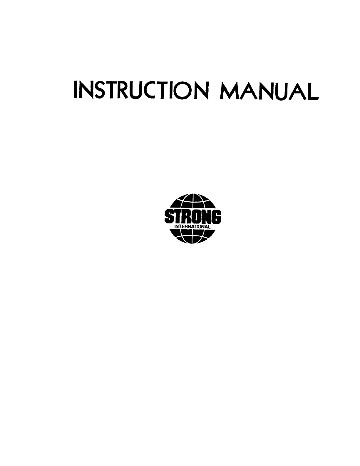
CLEAR THE SHUTTER BLADES and changeover/fire shutter douser(s) as required and
install the alignment kit as illustrated. Insert the aligning cord through the CinemaScope aperture plate, and use
an object of sufficient weight to keep the cord taut. Close the film gate to retain the test aperture plate.
LOOK THROUGH THE LAMPHOUSE ACCESS DOOR and locate the reflected image of
the aligning cord on the reflector. If the reflected image of the cord is not superimposed on the cord, that is, if
it appears above or below the cord, the projector is not aligned to the lamphouse reflector.
THE REFLECTOR is factory prealigned to the approximate optical center of the picture aper-
ture in the projector. Fine adjustment, to center the aligning cord in the test aperture, is done by loosening the (4)
hex head bolts securing the projector mounting arm and alternately tightening and loosening the (6) allen head
positioning screws. Retighten the (4) hex head mounting bolts after positioning the projector.
X90/007

BECAUSE OF MANUFACTURING TOLERANCES, it may be necessary to reposition the
reflector after having centered the aligning cord in the test aperture. To do so, loosen the #8 screws (Figure 2,
Item 54) from the back of the reflector flange and alternately tighten and loosen the spring-loaded allen head
reflector mounting screws (Figure 2, Item 8) to achieve the desired “single string” image on the reflector.
Retighten the #8 screws, and secure the locknuts, after completing the alignment. DO NOT overtighten to the
point where the lockscrews can warp the reflector flange.
ILLUSTRATIONS showing the correct and incorrect aligning cord images appear above.
The “CORRECT” illustration shows the cord covering its reflected image. The “INCORRECT” drawing,
showing the cord and its reflected image, denotes a small degree of misalignment. Observe the results of the
above adjustments by carefully watching the shifting position of the cord’s reflection.
UPON COMPLETION of the alignment procedure, remove the cord and its associated fix-
tures, and restore operation of the changeover/fire shutter douser. Store the alignment kit parts in a secure
location in the booth; replacement of a reflector will require a second alignment. Rotate the focus control knob
to center the anode support column in its travel path prior to installing the xenon bulb.
X90/008

SAFETY PROCEDURES
THE XENON BULB is highly pressurized. When ignited, the normal operating temperature
of the bulb increases the pressure to a level at which the bulb may explode if not handled in strict accordance to
the manufacturer’s operating instructions. The bulb is stable at room temperature, but may still explode if
dropped or otherwise mishandled.
REFER BULB REPLACEMENT and service to qualified personnel with adequate protective
clothing (face shield, clean cotton gloves, welder’s jacket). For routine lamphouse service, observe the follow-
ing procedures:
1. Allow the bulb to cool to room temperature before opening the lamphouse. Put on protective clothing
described above.
2. De-energize the xenon power supply at the AC source before opening the lamphouse compartment.
3. When possible, encase the bulb in its protective cover when cleaning or servicing the lamphouse inte-
rior. The bulb, when outside the lamphouse, must be encased in the cover.
4. Clean the bulb after it has cooled to room temperature. Do not touch the quartz envelope of the bulb;
fingerprints will burn in and create hot spots which may shorten bulb life. If fingermarks are made,
they should be carefully removed with methyl alcohol and cotton prior to bulb operation.
5. Never view an ignited xenon bulb directly. BLINDNESS OR PERMANENT EYE DAMAGE MAY
BE INCURRED.
6. Use only xenon bulbs designated as OZONE FREE. When possible, vent the lamphouse exhaust to
outside atmosphere.
7. Maintain the lamphouse blower(s) in good operating condition. Keep the blower inlet(s) clean for
unrestricted air flow.
8. To insure maximum bulb life, operate the lamphouse blower and the exhaust system for at least ten
minutes after extinguishing the bulb.
9. If returning a bulb for warranty adjustment, pack it in its original shipping container. Complete and
return all required warranty information.
10. Dispose of expired bulbs that are beyond warranty in the following manner: Wrap the bulb tightly in
several layers of canvas or heavy cloth. Place it on a hard surface and shatter the envelope with a sharp
hammer blow. DO NOT place an unshattered bulb in an ordinary refuse container.
11. DO NOT PERMIT UNAUTHORIZED PERSONNEL TO PERFORM OR ATTEMPT ANY PHASE
OF XENON BULB HANDLING OR SERVICE.
Anode
Cathode
Cathode Pin Seal
Anode Pin
Envelope
Anode End Cap
Seal
Cathode End Cap
X90/009

41-51185
31243 01598
81389
71241
7196900685
00685
00967
71242
71245
71969
NOTE: Cotter Pin 00967 required for
use with Hanovia XH1000HS
only.
X-90 BULB ADAPTERS
00685
71969
65410 71242
71241 0159881389
7109941-51107*
31245
71099
41-51107*
Anode Lead Supplied
with Bulb
01532
71969 00685
39191
01532
81341
01598
81343
81342
71099
31245
41-51107*
Anode Lead Supplied
with Bulb
* Do Not Deform 31245 Support Casting by overtightening 41-51107 Screw. Tighten Screw
snug only
2500 Watt; 2000 Watt Type “HS”
2000 Watt (Standard)
1000 - 1600 Watt
X90/010

XENON BULB INSTALLATION
THE X-90 CONSOLE is designed for operation with the following xenon bulbs ONLY. Bulbs
not listed below must be certified by their manufacturer as being 100% interchangeable with the listed bulbs,
and designated as ozone free. Refer to the SAFETY PROCEDURES before handling the xenon bulb.
WATTAGE HANOVIA OSRAM
1000 XH1000HS XBO1000W/HS OFR
1600 XH1600HS XBO1600W/HS OFR
2000 XH2000HW XBO2000W/H OFR
2000 XH2000HS XBO2000W/HS OFR
2500 XH2500HS XBO2500/HS OFR
BULB ADAPTER KIT 31934 is included with each X-90 console, and includes all adapters
and hardware required to mount any of the above bulbs. Parts shown for use with the 2500 watt bulb are also
used on 2000 watt “HS” bulbs now offered by numerous suppliers. It is recommended to store the unused
components of the kit in a secure location in the projection booth. They will then be available in the event of a
decision to change to a higher or lower lamp wattage.
THE SPLIT CATHODE Vblock behind the reflector is factory set to accommodate the 1.25"
(35mm) diameter of a standard 2000 watt bulb end cap. Sliding the segments closer together will raise the
center of the Vto allow for the smaller diameter of a 1000 or 1600 watt bulb end cap and cathode adapter
31244. Each segment mounts to the base using a single socket head screw; moving the segments equal distances
will maintain the optical center. The shorter ovarall length of the 2500 watt and 2000 watt “HS” bulb requires
the addition of a spacer block (81336) and use of a one-piece cathode support 71675. These components are
factory-installed when the X-90 is ordered for use with a 2500 watt bulb.
ASSEMBLE ALL BULB ADAPTERS as illustrated on the X-90 XENON BULB ADAPT-
ERS page to the bulb prior to insertion into the lamphouse. DO NOT apply torque pressure to the quartz vessel
of the bulb in this operation; handle the bulb by the metal end caps only. If possible, leave the bulb in its
protective enclosure when installing adapters. Do not touch the quartz vessel material with bare fingers.
NOTE CAREFULLY the position of the 31245 Anode Support Casting. It will assemble to
the bulb in (1) of (2) positions, with the horizontal portion either directed toward the bulb, or away from the
bulb, depending on the desired bulb wattage. This adapter must be correctly positioned to enable bulb focus.
Note also the correct hole location for the 71099 Bushing and mounting screw. The bushing must be in the
correct hole for proper bulb focus. Do not overtighten the mounting screw.
TWO 71969 LEAD ASSEMBLIES are supplied with the bulb kit. One lead assembly is
needed to connect the cathode contact clamp or adapter to the igniter post; the second lead is required as an
anode lead for 1000 and 1600 watt bulbs. The lead assemblies have two different size terminals; attach the
smaller terminal to the bulb clamp or adapter.
X90/011

BULB INSTALLATION (continued)
DISMOUNT THE UPPER COVER of the stainless steel bulb enclosure by removing the (2)
thumbscrews. Center the front bulb support pedestal by rotating the bulb focus knob adjacent to the douser
handle. Insert the bulb, with adapters mounted, into the lamphouse. Pass the cathode (-) end of the bulb through
the center hole in the rear of the reflector. Take care not to dent or scratch the surface of the reflector. Rest the
cathode end cap of the bulb in the Vblock behind the reflector, and mount the anode support casting to the anode
pedestal using the 71099 Bushing and 41-51107 Screw. Again, insert the bushing through the correct hole. Do
not overtighten the mounting screw; excessive torque may deform the 31245 casting.
RUN THE CATHODE LEAD through the insulated bushing at the back of the bulb enclosure
and connect it to the left (output) terminal post of the igniter. Connect the anode (+) lead to the rear terminal of
the shunt. Dress the anode lead close to the upright pedestal to minimize the shadow. Make certain all DC
connections are tight, and replace the stainless steel bulb enclosure cover.
REFER TO THE DOCUMENTATION packaged with the xenon bulb. It contains important
information prepared by the manufacturer of the bulb, including the recommended nominal current level at
which the bulb will begin operation. The current output adjustment for the X-90 power supply is located above
the ammeter. Do not exceed the maximum current level specified by the bulb manufacturer; the X-90 power
supply is capable of overdriving the xenon bulb.
STORE THE BULB PACKAGING and the warranty documentation in a secure location in the
projection booth. Record the installation date and lamphouse hours on the Bulb Record card on the back of the
console, or on the Xenon Bulb Record on the back cover of this manual.
TYPICAL CURRENT LEVELS
Wattage Nominal Current Do Not Exceed
1000 50 A. 58 A.
1600 65 A. 70 A.
2000 75 A. 90 A.
2500 90 A. 100 A.
X90/012

BULB ALIGNMENT AND OPERATION
CLOSE AND LOCK the lamphouse access doors. Turn on the exhaust system. Close the
douser. Energize the distribution panel by turning the MASTERcircuit breaker to the ONposition (light ON).
When the LAMP circuit breaker is closed, the indicator lights for “POWER,”“AIR,”and “DOOR”will light.
IN NORMAL MODE, the LAMP “ON”indicator and the xenon bulb will not light until cued
by the automation controller. For test purposes, select “MAN.”mode (upper position). The LAMP “ON”
indicator will light, and the xenon bulb will ignite.
CHECK THE BULB CURRENT at the am-
meter. If not operating within specified range, adjust
the xenon power supply to obtain the correct output.
The operating current range is noted in the xenon bulb
warranty information. Do not exceed the maximum
current specified by the bulb manufacturer.
A NEW XENON BULB is normally operated
at or near its nominal current. As the bulb ages, the
quartz envelope normally will darken. The current can
then be gradually increased to compensate for the light
loss caused by the darkening envelope.
PRESS THE “LAMP VOLTS”switch to
change the ammeter to display arc voltage. To deter-
mine exact wattage, multiply volts time amperes.
THE ANALOG ELAPSED TIME METER (as illustrated) will record the hours of bulb
operation. The meter runs only when the xenon bulb is operating.
THE OPTIONAL DIGITAL INSTRUMENT PANEL continuously displays the bulb current
(A), arc voltage (V), wattage (W), and elapsed hours. Elapsed hours are displayed as Bulb Hours (BLB) and
Total Hours (HR). Bulb hours can be re-set to zero after replacing the xenon bulb. Prior to bulb ignition,
electrical data is displayed as zeros, but the backlighting of the display screen indicates that power is ON.
ADJUSTMENT CONTROLS are provided to correctly position and focus the xenon bulb.
Bulb adjustment controls, located on the distribution panel immediately above the MASTER circuit breaker,
position the bulb inside the reflector on the horizontal and vertical planes. The focus control knob, located
adjacent to the douser handle, moves the bulb in and out of the reflector on the horizontal plane.
REMOVE THE PROJECTION LENS, turn on the projector motor, and open the douser. A
black spot should appear in the center of the screen. Adjust, tilt, or reposition the console as required to center
the spot on the screen.
X90/013
A SCISSORS JACK is mounted to the rear of the console base to permit setting the projection
angle. To adjust, open the rear access door and loosen the (2) lock nuts on the inside of the upright frame. Tilt
the console to the desired projection angle by operating the jack with a 3/4 inch socket or box end wrench. When
set to the correct angle, retighten the lock nuts.
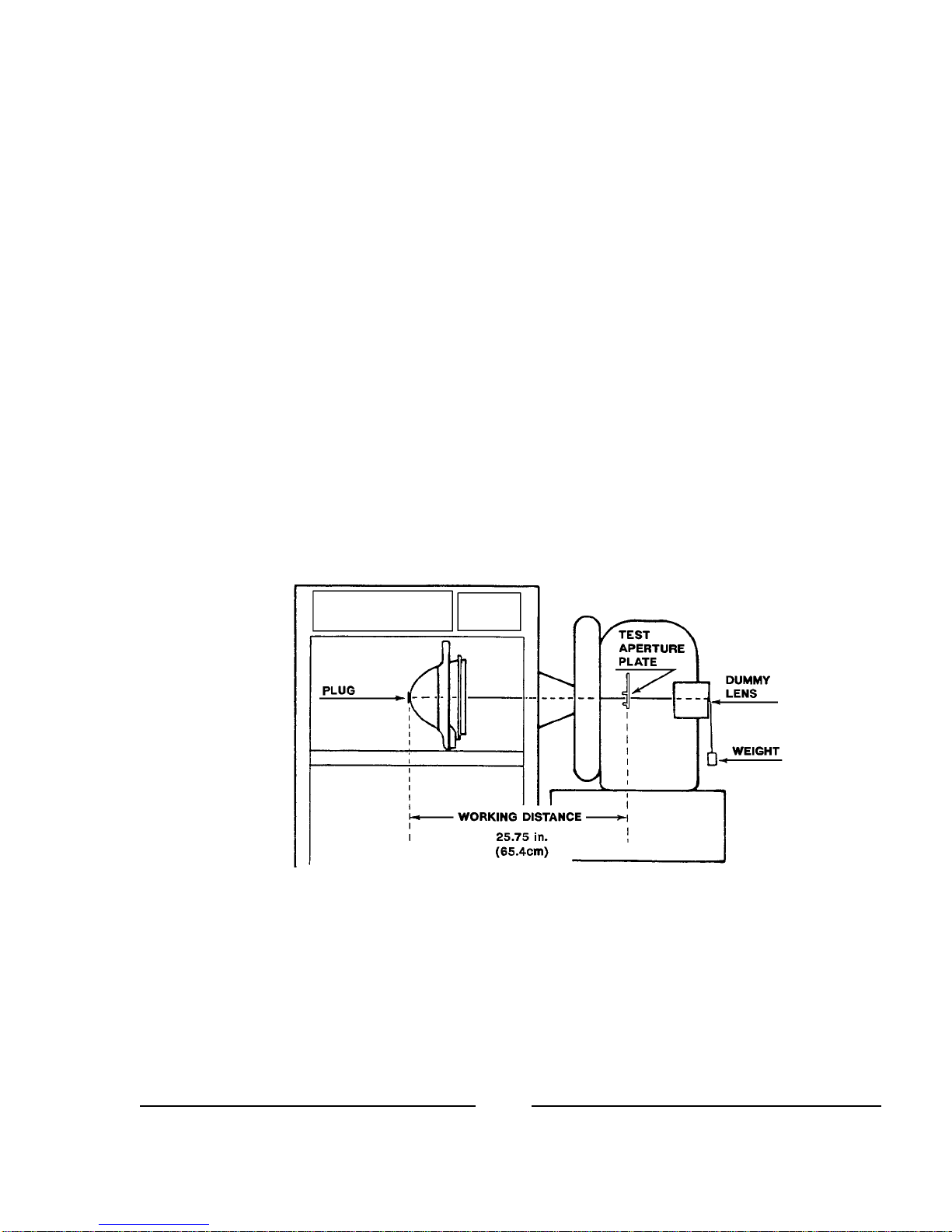
AN IMAGE similar to that illustrated on the
left should appear on the screen. Adjust the focus control
knob to sharpen and define the spot inside the shaded pro-
jection of the reflector center hole. Using a flat bladed
screwdriver, rotate the VERTand HORIZadjustments until
the black spot is centered in the shadow as illustrated.
IF THE SHADOW of the bulb anode cable
is pronounced, shut off the lamp, allow the bulb to cool,
and open the access door. Dress the anode cable closer to
the bulb support pedestal.
THE SPLIT CATHODE Vblock behind the reflector is factory set to accommodate the 1.25"
(35mm) diameter of a standard 2000 watt bulb end cap. Operate the focus control knob adjacent to the douser
handle and observe the anode shadow as it moves inside the reflector center hole. The dark spot should remain
centered inside the shaded area. If the anode shadow raises or lowers as the bulb tracks forward or back, the
split cathode Vblock must be adjusted.
SLIDING THE SEGMENTS together or apart will raise or lower the center of the V. Each
segment mounts to the base using a single socket head screw; moving the segments equal distances will maintain
the optical center. The one-piece cathode support 71675 used with 2500 watt and 2000 watt “HS” bulbs should
require no such adjustment.
WHEN THE ANODE SHADOW is centered in the reflector center hole, insert the CinemaScope
aperture plate into the projector and install the projection lens. Adjust the focus control knob until the light field
on the screen is uniform. Close the lamphouse douser frequently during this operation to allow the lens to cool.
Prolonged lamphouse operation without film will damage the projection lens. After a uniform field is achieved,
file aperture plates to fit the screen and masking.
ALLOW THE BLOWER AND EXHAUST SYSTEM to operate for (10) minutes after extin-
guishing the bulb. This measure will prolong bulb life, and is required by the bulb manufacturer.
DAILY OPERATION
1. Turn all circuit breakers ON; close the lamphouse douser. Turn on the exhaust system (if not wired through
the console distribution panel). Place the LAMPswitch in the ON position to ignite the xenon bulb. Open
the lamphouse douser only after the projector is running. DO NOT operate the xenon bulb for over twenty
(20) minutes with the lamphouse douser closed.
Support Pedestal
Shadow
Reflector
Hole
Anode
Shadow
PROJECTED IMAGE (without Lens)
X90/014

2. If using a booth automation system, leave the lamphouse douser OPEN. The automation controller will
switch the xenon bulb ON after starting the projector motor. At the shut-down cue, or in the event of a film
break or other automation failsafe fault, the xenon bulb will extinguish. All blowers will continue to operate
and cool the bulb and power supply. The automation controller will re-ignite the bulb upon the next show
start cue, or after restoration of the fault. The LAMP switch overrides automation control.
CAUTION: If operating the lamphouse in the manual mode (by use of the LAMP switch), as an override to a
faulty lamphouse ignition circuit in an automation controller, DO NOT leave the console unattended. In the
event of a film break, platter head wrap, or other automation fault, the bulb will not extinguish, resulting in
possible print and/or projector damage.
3. At the end of the day, allow the console and exhaust blowers to continue operating for at least ten minutes
after extinguishing the xenon bulb. This measure assures proper bulb cool-down, and is required by most
bulb manufacturers to comply with warranty requirements.
BULB ROTATION
MOST XENON BULB MANUFACTURERS recommend and/or require rotation of horizon-
tal bulbs at 50% warranty life. Refer to the warranty information packaged with the xenon bulb for specific
user requirements.
TO ROTATE THE BULB, loosen the socket head screw in the cathode clamp and remove the
anode lead terminal from the shunt. Rotate the bulb 180 degrees, re-attach the anode lead terminal, and securely
tighten the cathode clamping screw.
ADJUST THE XENON POWER SUPPLY to increase bulb operating current to or just below
the maximum level specified for the bulb. Project a white light to the screen to check for an even field and
correct the bulb positioning as required. Operate the xenon bulb at this higher current level for one or two
performances, and then return the power setting to its previous level. Temporary operation of the bulb at high
current following bulb rotation will restore the cathode tip and enhance ignition at the new arc position.
BULB WARRANTY RETURNS
RETURN BULBS upon which a warranty claim is being made to the theatre equipment dealer
through whom the bulb was purchased. Pack the bulb in its original shipping carton with the protective cover
over the bulb. Complete and enclose all warranty forms supplied by the bulb manufacturer.
WARRANTY CREDIT will not be allowed if the bulb failure is related to mishandling,
improper installation, faulty supporting equipment, or abuse.
REFLECTORS damaged by a xenon bulb explosion should be forwarded to the bulb supplier
for warranty adjustment. Include an invoice copy authenticating the cost of the replacement reflector.
X90/015

DIGITAL DISPLAY
UPON ENERGIZING the LAMP circuit, the backlighting will illuminate the LCD screen.
When all blowers are operating and all access doors are closed and correctly secured, the display will appear as shown:
000V 000A 0000W
1234BLB 12345HR *
FOR PURPOSES OF ILLUSTRATION, the above display indicates a non-operating bulb
with 1,234 hours of use installed into a console with 12,345 hours of operation. The asterisk (*) at the end of the
second line, when flashing, indicates that the display is active and awaiting input. Upon bulb ignition, the upper
line will display the arc voltage (V), the DC current (A), and the operating wattage (W) of the bulb; the asterisk
symbol will be replaced by a plus (+) sign. The figures will shift for the first few moments of xenon bulb
operation, but will stabilize after the bulb reaches operating temperature and pressure.
IN THE EVENT of an open interlock switch, the lower line will display an appropriate diagnos-
tic measure, i.e. CHECK REAR DOOR or CHECK BLOWER. Diagnostic messages are defined as follows:
CHECK REAR DOOR: Make certain the rear console access door is closed and locked.
CHECK FRONT DOOR: Make certain the operator’s lamphouse access door and locked.
CHECK BLOWER: Make certain the squirrelcage blower below the igniter is energized and operating,
and that the ducting to the bulb compartment is secure.
THE OPTIONAL 31902 EXHAUST AIR VANE SWITCH, if used, is wired in series with the
air flow switch mounted to the base plate below the reflector. Check both switches in the event of a CHECK
BLOWER error message.
WHEN THE INTERLOCK CIRCUIT is complete, closure of the LAMP switch, or the auto-
mation closure (3 & 6), will energize the contactor of the xenon power supply. The high open circuit (“no load”)
DC voltage will be displayed. When the open circuit voltage reaches 140 V.DC, the igniter will generate a RF
pulse to bridge the gap between the bulb electrodes. This pulse, coupled with the high open circuit DC voltage,
will ignite the bulb. The voltage reading will then fall to the bulb’s sustaining level, and the DC amperes (A) and
wattage (W) will be displayed continuously until the bulb is extinguished.
FAILURE of the xenon power supply to generate the high open circuit voltage will not cause an
error message to appear, but will be apparent by the zero voltage and current reading displayed on the LCD
screen. Make certain the (2) circuit breakers on the power supply cabinet are ON and not tripped, and check the
line fuse. These components are accessible through the off-operator side door of the X-90.
X90/016

THE STRONG SWITCHING POWER SUPPLY also includes Phase Loss Detection and
Brown-Out Protection which will disable the power supply in the event of problems in the AC supply line. See
the power supply Instruction Manual for detailed information.
ELAPSED HOURS will begin counting upon bulb ignition. Bulb hours (BLB) are limited to
four digits, and are re-set when the xenon bulb is replaced. To re-set bulb hours, press the RESET button
accessible through marked hole below the LCD screen. The 5/64" allen wrench used to tighten the front bulb
collar set screw is the correct diameter to clear the hole. NOTE: when recording start-up and removal hours on
the Xenon Bulb Record, use the total elapsed hours (HR) figures. The (BLB) figure, re-set upon installation of
the bulb, is a convenience feature ONLY. Basing records of the lamp system on the total hours (HR) figures
permits an accurate and ongoing history of bulb usage.
IF THE XENON BULB fails to ignite after several igniter pulses, additional diagnostic mes-
sages will display on the LCD screen:
CHECK PWR SUPPLY: If no DC current is sensed, and voltage does not exceed 125 V.DC, check the xenon
power supply. Repair or replace as required.
CHECK IGNITER: If the DC open circuit voltage reaches and exceeds 140 V.DC and the igniter fails to
pulse, replace the igniter.
DIAGNOSTIC MESSAGES serve as prompts and suggestions but do not replace traditional
troubleshooting procedures. If an access door is closed and secured but transmits an error message, check the
subject door interlock switch with an ohmmeter and replace if defective. Dirt or dust fouling an air vane switch
will cause a “blower” error message. A “power supply” or “igniter” error message might be caused by a loose
or oxidized connection.
X90/017

MAINTENANCE
VERY LITTLE MAINTENANCE, aside from routine cleaning, is required for the X-90. The
cleaning intervals must be determined by the dirt and dust conditions at each installation.
ALLOW THE BULB to cool to room temperature before opening the lamphouse compart-
ment. Observe all safety procedures when working around the xenon bulb.
CLEAN THE REFLECTOR with a clean, dust-free soft cloth. If excessively soiled, the re-
flector may be cleaned with a commercial liquid glass cleaner. DO NOT use abrasive cleaners of any kind.
LUBRICATE THE SQUIRRELCAGE BLOWER MOTOR periodically using an all-purpose,
non-detergent oil. Clean the air inlet screen and inspect the impeller vanes for dust build-up. The front bulb seal
blower is permanently lubricated and requires no oiling, but the blower grille should be cleaned.
VACUUM the air intake and exhaust grilles on the xenon power supply cabinet. The intake
grille is easily accessible through the back door of the console. It may be necessary to loosen the 1/4-20
fasteners securing the power supply retaining strap, and slide the power supply slightly toward the back, to
thoroughly clean the outlet grille. Power supply blowers are permanently lubricated and require no oiling.
DO NOT allow dust build-up to collect on the surface of the xenon bulb. Foreign material will
rapidly burn into the quartz envelope and can shorten bulb life. Clean the bulb envelope periodically using a
clean cloth and alcohol. Rinse with distilled water.
CHECK ALL ELECTRICAL CONNECTIONS for tightness. Inspect DC termination points
for discoloration; re-attach loose connections. Clean or replace oxidized terminals.
X90/018
Table of contents


