BELLTEC TM48HTL Installation manual

SET-UP AND OPERATING INSTRUCTIONS
TM48HTL - TM48GRS

BELLTEC INDUSTRIES, INC.
P. O. Box 270
Belton, TX 76513
LIMITED WARRANTY
*Belltec Industries, Inc., ("Belltec") warrants equipment manufactured by it
to be free under normal use and service from defective parts for a period of
1 year from the date of delivery by us or our Dealer to the original
purchaser.
Parts claimed defective must be removed from the machine at the Buyer's
expense and returned to the factory, for inspection, by prepaid freight,
within 15 days after Buyer learns of facts upon which claim is made. Parts
found to be defective will be promptly replaced or repaired and returned
without charge.
Belltec's obligation and liability under this warranty is expressly limited
to repairing or replacing at Belltec's option any part which appears to
Belltec upon inspection to have been defective in material or workmanship.
This warranty shall not apply to component parts or accessories to products
not manufactured by Belltec and which carry the warranty of the manufacturer
thereof, or to normal maintenance, or to normal maintenance parts.
Replacement or repair parts installed in the product covered by this warranty
are warranted only for the remainder of the original warranty as if such
parts were original components of said product.
LIMITATION OF DAMAGES: Belltec's obligation under this warranty shall not
include any transportation charges, costs of installation, duty, taxes or any
other charges whatsoever or any liability for direct, indirect, incidental or
consequential damage or delay. Belltec's liability for any and all losses and
damage to Buyer resulting from any cause whatsoever, including any negligence
or breach of any form of warranty, express or implied, by Belltec, alleged
damage or defective goods, irrespective of whether such defects are
discoverable or latent, shall in no event exceed the purchase price of the
particular goods. Any improper use including operation after discovery of
defective or worn parts not approved by Belltec or any alteration or repair
by other in such manner as in Belltec's judgment affects the product
materially and adversely shall void this warranty.
No employee, dealer, salesman, or representative is authorized to change this
warranty in any way or grant any other warranty unless such change is made in
writing and signed by an officer of Belltec at its home office.
THE FOREGOING WARRANTIES ARE EXCLUSIVE AND ARE IN LIEU OF ALL OTHER
WARRANTIES (WHETHER WRITTEN, ORAL OR IMPLIED) INCLUDING WARRANTIES OF
MERCHANTABILITY AND WARRANTY OF FITNESS FOR A PARTICULAR PURPOSE.
*Equipment used in commercial service such as, but not limited to, commercial
fencing or drilling, guard rail installers, construction companies or public
entities, is warranted for a period of 90 days from date of delivery to the
original purchaser.

1
TABLE OF CONTENTS
1. SAFETY INSTRUCTIONS........................................... 1
2. SAFETY PRECAUTIONS............................................ 2
3. SAFETY SIGNS (DECALS)......................................... 6
4. ASSEMBLY...................................................... 8
a) ASSEMBLY PRECAUTIONS .................................... 8
b) MOUNTING ON TRACTOR ..................................... 9
c) ASSEMBLY - TM48HTL ...................................... 9
d) ASSEMBLY - LOCKBARS ..................................... 9
e) INSTALLING A GRS HYDRAULIC CYLINDER KIT ................. 10
5. ATTACHING THE DRIVELINE....................................... 11
a) LENGTH OF DRIVELINE ..................................... 11
6. BEFORE DRILLING FIRST HOLE.................................... 11
a) ADJUSTING LOCKBARS ...................................... 11
b) LEVELING DRILLING MACHINE ............................... 11
c) CHECK DRIVELINE--RELIEF VALVE—SKIDS ..................... 11
d) INSTALLING AUGER ........................................ 12
7. CHECK LIST BEFORE STARTING A NEW DIGGER....................... 13
8. TO ADJUST THE RELIEF VALVE.................................... 13
9. TRANSPORTING.................................................. 14
10. LUBRICATION................................................... 14
11. OPERATING INSTRUCTIONS........................................ 15
a) DRILLING HOLES IN DIRT .................................. 16
b) DRILLING SOLID ROCK ..................................... 17
c) DRILLING LARGE CHUNK ROCK ............................... 17
12. PUFF DRILL.................................................... 17
13. MAINTENANCE................................................... 18

2
THIS SAFETY ALERT SYMBOL IDENTIFIES
IMPORTANT SAFETY WARNING MESSAGES.
CAREFULLY READ EACH WARNING MESSAGE THAT
FOLLOWS. FAILURE TO UNDERSTAND AND OBEY A
SAFETY WARNING, OR RECOGNIZE A SAFETY
HAZARD, COULD RESULT IN AN INJURY OR DEATH
TO YOU OR OTHERS AROUND YOU. THE OPERATOR IS
ULTIMATELY RESPONSIBLE FOR THE SAFETY OF HIMSELF, AS
WELL AS OTHERS, IN THE OPERATING AREA OF THE POST HOLE
DIGGER.
SAFETY INSTRUCTIONS - READ CAREFULLY
Do not take chances - be a careful opera-
tor. Read this manual thoroughly before
attempting to operate the drilling ma-
chine. Working with unfamiliar equipment
can cause accidents. If after thoroughly
reading this manual, you have any ques-
tions regarding safety or understanding
the intended uses and the limitations of
your Belltec drilling machine, contact the
Belltec office or your authorized dealer.
We will be more than happy to assist you
in the proper use of this machine. Be
safety conscious.
The safety of the operator is one of the prime considerations
of Belltec engineers. Shielding, adjustments, and other
safety features were built into the machine wherever possible.
The owner, operator, and person who is directly responsible
for the operation of the digger must accept his responsibility
for safe operation. With your cooperation, by not taking
risks, and understanding the manual in full, to know how to be
careful, accidents can be prevented. If the person who will
operate this machine does not read or understand English, it
is the owner's responsibility to translate or provide an in-
terpreter.
You will find in this manual notes, warnings and cautions.
This does not mean that the digger is dangerous. Nor does it
mean that they should be taken lightly. You must exercise the
utmost care and caution in use of the digger, and realize that
it is a powerful machine that can cause serious injury or
death if improperly used. Hitching and removing the digger,
along with digging with other workmen present are the times
you need to be extremely cautious.
ACCIDENTS ARE PREVENTABLE WITH YOUR
HELP
SAFETY PRECAUTIONS
THIS MANUAL MUST BE READ AND UNDERSTOOD IN ITS ENTIRETY BEFORE
ATTEMPTING ANY ASSEMBLING, OPERATION, INSTALLATION,
MAINTAINING OR REPAIRING OF THE DIGGER. STRICTLY OBSERVE THE
NOTES, CAUTIONS AND WARNINGS NOTED THROUGHOUT THIS MANUAL.
3
OPERATE DIGGER ONLY FROM TRACTOR SEAT.
KEEP ALL OTHERS AT LEAST 10 FEET AWAY.
A careful operator is the best protection against accidents.
Most accidents involving operators of equipment are listed be-
low:
1) Only the operator should be allowed on the tractor when
the digger is in operation. Make sure they are instructed
and capable of safe operation. Carefully supervise inex-
perienced operators. Never allow children to operate the
digger.
2) Learn how to operate this machine in a safe, open area be-
fore operating in tight quarters or in conjunction with
other equipment or people.
3) Make sure everyone is away from the digger and clear of
the digging area before starting the tractor or digger.
4) Be sure to apply the tractor brakes firmly and put the
tractor in park, if so equipped, before start-
ing to dig a hole.
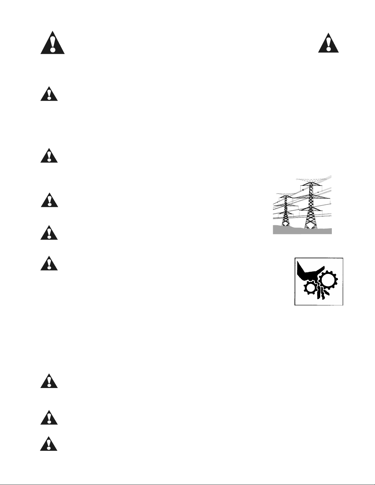
5) Be aware of overhead and underground power
lines and utilities. Never allow the digger or
tractor to touch power lines. Consult local
utilities authority before digging.
6) Never attempt to clear grass build-up, dirt or
debris off the machine unless the driveline has
stopped rotation, the tractor is shut off, and the parking
brake on the tractor is engaged.
7) Always use extreme caution when attaching the digger
to the tractor. Keep all parts of your body from be-
tween the tractor and the digger during attachment.
Never place any part of your body where it would be
in danger if movement should occur while attaching,
maintaining or repairing the digger.
8) Use slow, deliberate, and careful movement in getting
onto and off the tractor. Be especially careful in muddy
conditions. Disengage the PTO and shut off the tractor
engine before leaving the tractor.
9) Disengage power take-off and disengage auxiliary hydrau-
lics and shift tractor into Neutral or Park before start-
ing tractor.
10) Transport the tractor/digger slowly over rough terrain.
11) Remain on the tractor until it has come to a complete
stop. Do not allow anyone on the digger while the tractor
is running.
12) Use extreme caution when digging close to ditches and in
soft soil. Be sure tractor brakes are set.
13) Be especially careful when workman or spectators are in
the digging area. Do not operate digger with persons
within 10 feet of the auger.
14) When digging on sloping ground or hillsides, be careful
that the slope would not cause tractor to upset. Lock

4
tractor brakes when digging.
15) Keep tractor platform free of dirt, trash, grease and oil.
16) Strictly observe OSHA's safety requirements. Know the
regulations and laws that apply to this type of equipment
in your area and make sure that this machine is properly
equipped to meet these laws and regulations.
17) Always lower the digger completely to the ground before
leaving the tractor. Never leave equipment unattended
with the tractor running.
18) Do not work on or make any adjustments to the
tractor or digger while either is in operation.
Turn off tractor engine, lower digger to the
ground and operate digger control levers to re-
lieve residual hydraulic pressure before adjust-
ments or repairs are made, or when leaving the
tractor. Do not leave the digger unattended with
the auger or mainframe raised. Always lower it to
the ground.
19) Be sure the relief valve on the digger is set to a pres-
sure that is low enough so that the tractor wheels will
not lift off the ground when down pressure is applied to
the auger.
20) Escaping hydraulic oil under pressure can cause
personal injury. Make sure all hydraulic con-
nections are tight and no hose damage is pre-
sent. Check and straighten twisted hoses. Do
not attempt to repair or tighten hoses when un-
der pressure, with the engine running, or when
the unit is raised. Before disconnecting lines
to the drilling machine's hydraulic cylinders,
be sure to relieve all hydraulic pressure. If a
hydraulic leak is suspected, always search for
the leak with a piece of cardboard instead of
the hand, as escaping hydraulic oil can penetrate the skin
causing injury or death. Make sure all operating and ser-
vice personnel know that immediate doctor's attention is
required if hydraulic fluid penetrates skin.
21) When digging rocky soil, always wear safety
glasses.
22) Always wear safety glasses and appropriate protec-
tive gear when working on the digger, particularly
when driving pins or teeth with a hammer.
23) Never allow children to operate the tractor or dig-
ger. Keep tractor keys where they are not accessible to
children and take all precautions necessary to prevent
children from operating the tractor or digger.
24) Securely block up the digger. Use front stands when the
digger is removed from the tractor. Even when digger is
attached to tractor, supporting the digger with front
stands when not in use will unload the tractor and hitch.
25) When moving the tractor or digger on the road or highway
always use appropriate lights and slow moving vehicle
warning symbols.
26) Be sure tractor is weighted to provide 20% of the total

5
weight on the front wheels with the digger in transport
position.
27) Know your tractor controls and how to stop hydraulic power
and stop tractor engine quickly in an emergency.
28) If a safety shield is removed for any reason, it must be
replaced before the machine is again operated. Always use
and maintain in place all PTO guards furnished with the
digger.
29) Never crawl under the machine for any reason, it may fall
on you. Never poke anything near the rotating auger.
30) We suggest that a careful operator be sure that his
tractor has a roll bar or roll cage and that a seat
belt be installed on the tractor to prevent the op-
erator from falling off and being injured by the
drilling machine. The operator is responsible for
his own safety.
31) This digger is designed for use on 540 RPM PTO
tractors. Do not use any higher RPM PTO.
32) Check the machine frequently to be sure there are no loose
bolts. This includes the auger stem bolts and the hub
nut. Be sure to immediately tighten any loose nuts with
the proper tools.
33) Before digging or otherwise operating the machine,
you should carefully inspect the area to be worked,
looking for and noting all gullies, or ditches, etc.
and removing any posts, trash, wire, and other ob-
stacles or potential hazards.
34) Please remember that it is IMPORTANT that you read
and heed the safety signs (decals) on the digger, and the
safety rules set forth above. Clean or replace all safety
signs (decals) if they cannot be
clearly read. They are for your
own safety as well as the safety
of others. We cannot be there
to make sure that you follow
these rules of safe operation.
The safe use of this machine is
strictly up to you, the opera-
tor.
6
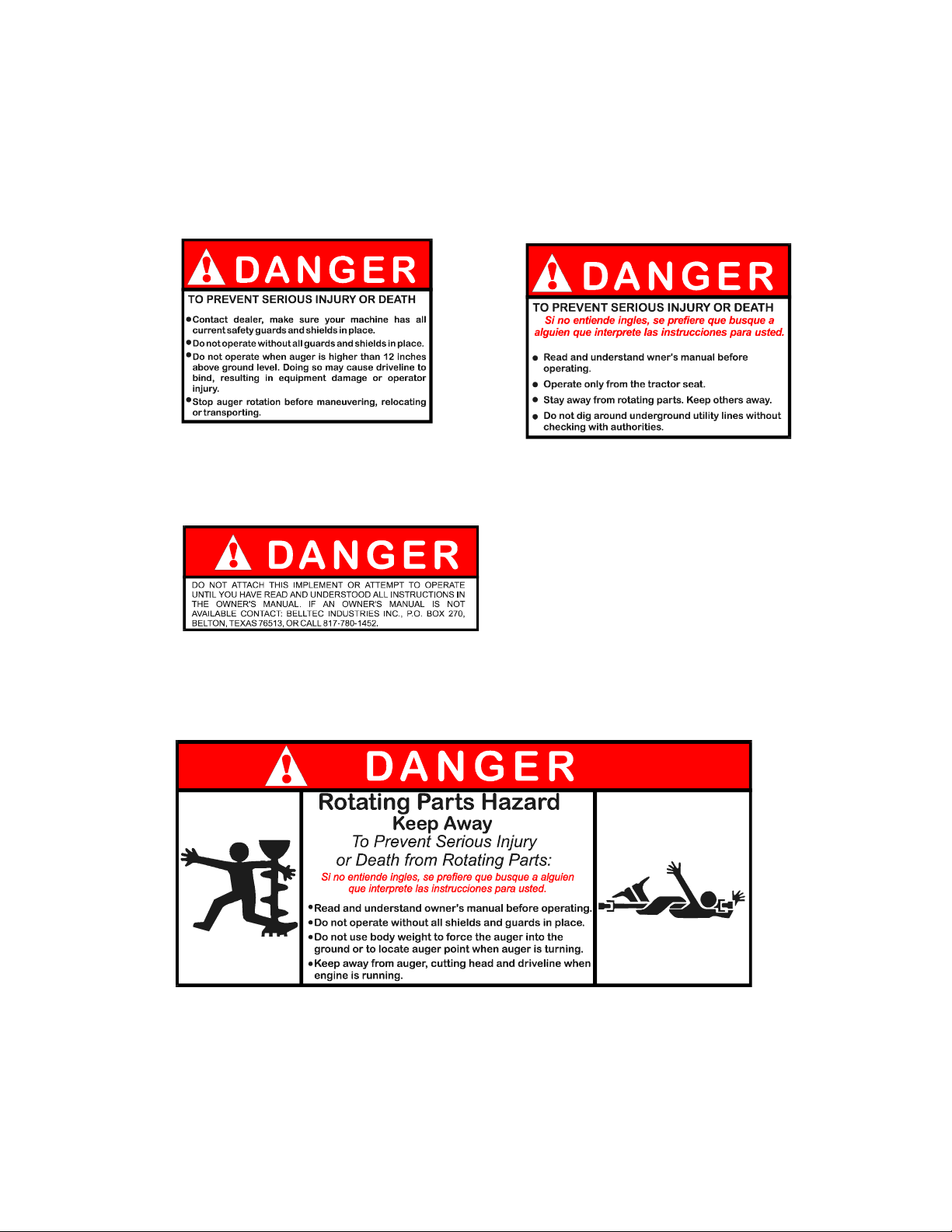
SAFETY SIGNS (DECALS)
Make sure these and all other safety labels are in place and readable
before operating this machine. We will gladly furnish replacement
labels if they become damaged or unreadable.
Part Number 111760
PART NUMBER 111759
QUANTITY - 2 QUANTITY - 1
LOCATION: ON THE SIDE OF THE LOCATION: ON TOP TUBE OF
GEARBOX SHIELD. HITCH
PART NUMBER 111763
QUANTITY - 1
LOCATION: ON TOP OF LEFT UPPER BRACE
PART NUMBER 111758
QUANTITY - 2
LOCATION: ONE TOP REAR OF THE REAR MAINFRAME SHIELD
ONE ON FRONT SHIELD
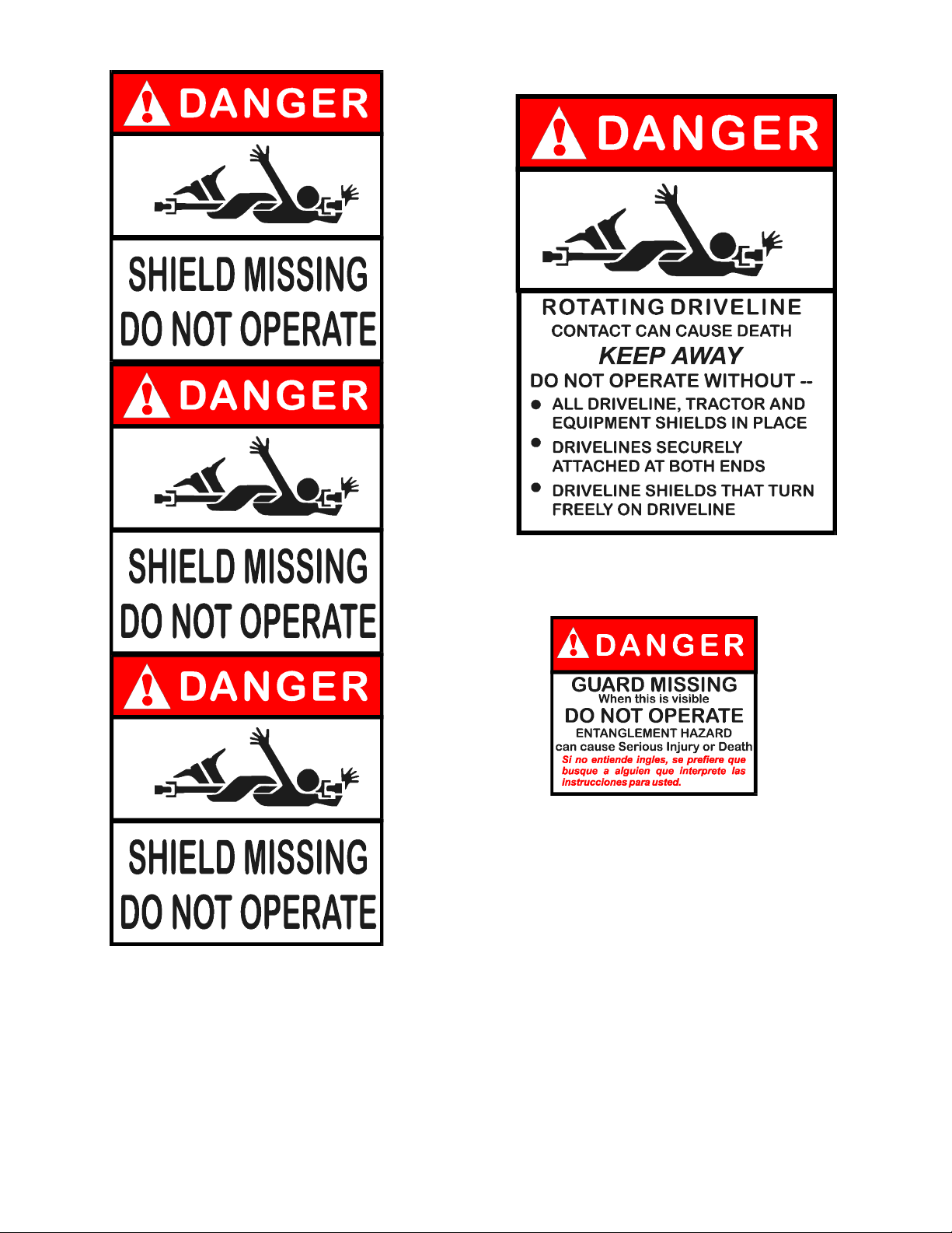
7
PART NUMBER 111764
QUANTITY - 1
LOCATION: ON SAFETY SHIELD OF
DRIVELINE.
PART NUMBER 111762
QUANTITY - 1
LOCATION: ON MAINFRAME
BEHIND FRONT SHIELD
PART NUMBER 111765
QUANTITY - 1
LOCATION: OUTER METAL TUBE
OF DRIVELINE
8
ASSEMBLY
PREPARATION FOR MOUNTING ON TRACTOR
Since your BELLTEC DRILLING
MACHINE (DIGGER) has been assem-
bled at the factory, only a
minimum of assembly and prepara-
tion will be required.
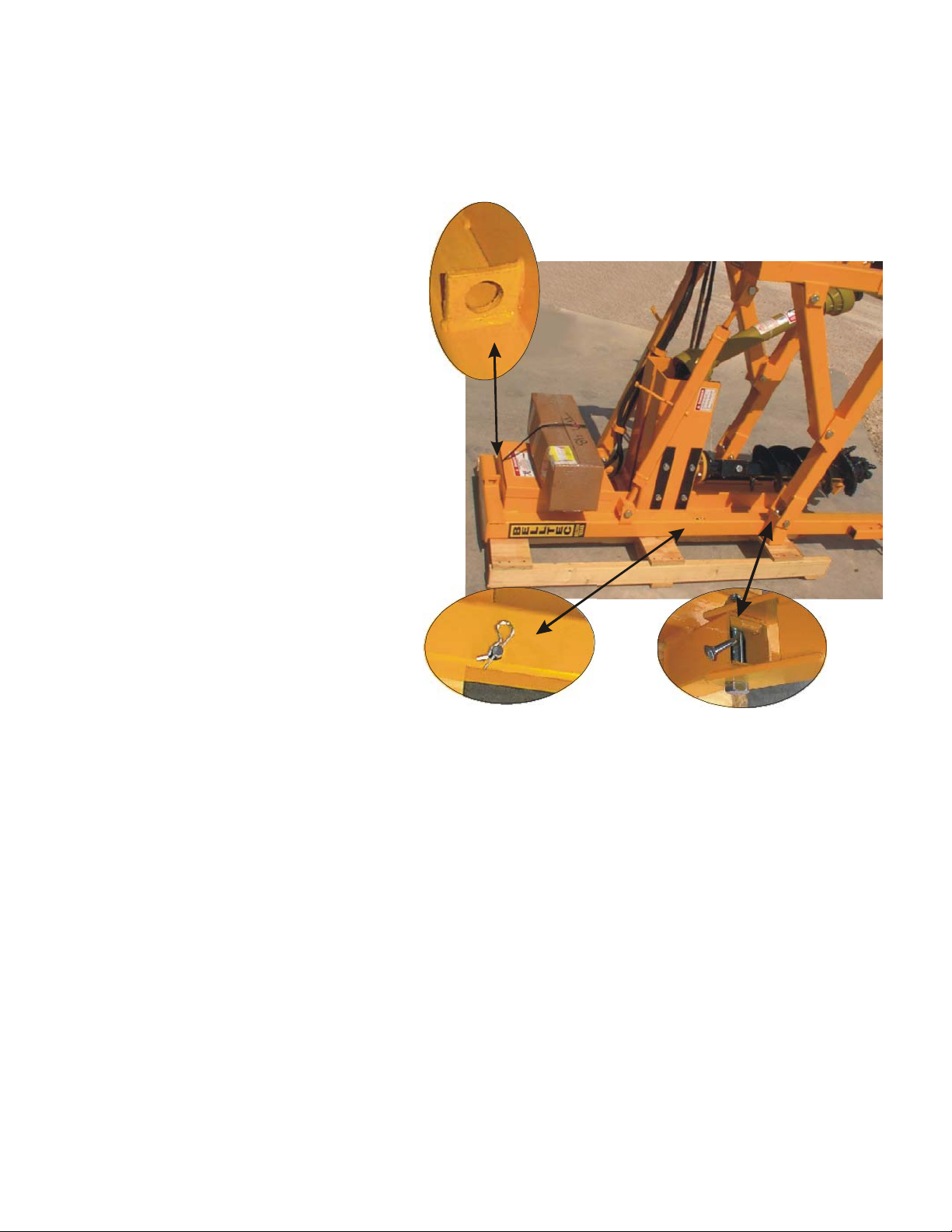
If the digger was shipped by
commercial carrier, it will be
fastened to a special pallet ly-
ing on its back.
Before attempting to stand dig-
ger upright, locate the safety
transport pin located near mid-
way of the mainframe tube. (ref-
erence picture) Be sure it is in
place before lifting digger so
carriage and gearbox will not
fall down while lifting.
To stand digger upright, if
still on the pallet, place under
a safe lifting device, such as a
chain hoist, or electric hoist
if available. If a forklift or
front-end loader is used, be
sure to place on a concrete
floor or other level, solid
area. Remove "J" bolts which
hold digger to pallet, as well
as any wire or strapping. Re-
move any augers or other parts
that may be fastened the to pal-
let.
A hook eye has been provided at the front, near the top of the digger. Securely
fasten hook or chain to hook eye before lifting. BE SURE EVERYONE IS CLEAR OF
AREA BEFORE LIFTING SO DIGGER WILL NOT FALL ON THEM IF CHAIN OR HOOK COMES
LOOSE.
After taking aforementioned precautions, slowly lift digger until skids on the
mainframe and park stands on the hitch are firmly resting on the floor or solid
ground.
The digger should now be ready for mounting on the tractor.
HOOK EYE
TRANSPORT
PIN
“J” BOLT

9
MOUNTING ON TRACTOR
1) THE BELLTEC DRILLING MACHINE hitch is made with the
proper spacing for Category I hitches (approxi-
mately 26"). If machine is being mounted on a
Category II hitch tractor (approximately 32" spac-
ing), prepare the tractor by changing rub blocks,
or sway chains, etc. so that hitch arms
will fit 26" spacing. Be sure drilling
machine hitch is equipped with correct
size pins for your tractors.
2) Align tractor lift arms with drilling
machine hitch pins and secure with lynch
pins.
3) INSTALLING HYDRAULIC TOP LINK (TM48HTL)
- Attach hydraulic top link to top link
bracket on tractor using the pin pro-
vided with the tractor.
4) Plug hydraulic hoses for main lifting
and down pressure cylinders into
tractor hydraulic system.
5) Plug hydraulic hoses on top link into
tractor hydraulic system. Extend cyl-
inder rod to align ball joint with
bracket on drilling machine hitch and
secure with hitch pin provided. On
tractors with top link brackets with
multiple holes, such as the one in the
photograph at right, the operator
should choose a combination of tractor
top link bracket hole and hitch top
link bracket hole (see middle photo-
graph this page) such that when the top
link is approximately half extended,
the drilling machine will be close to
plumb and the skids will be 4”-6” off
the ground. (see bottom photograph this
page)
6) Adjust length of cylinder so hitch frame
is vertical and square with the ground.
7) INSTALLING LOCKBARS: Attach male shaft
half with ball joints to the extension
of the lower hitch pins, located to the
inside of the drilling machine hitch
(bottom Photograph this page) and secure
with lynch pins. Slide female tube half
of lockbars onto the shaft half and at-
tach to the pin located on the tractor
end of the hydraulic top link. (see
photograph)
MALE
LOCKBAR

10
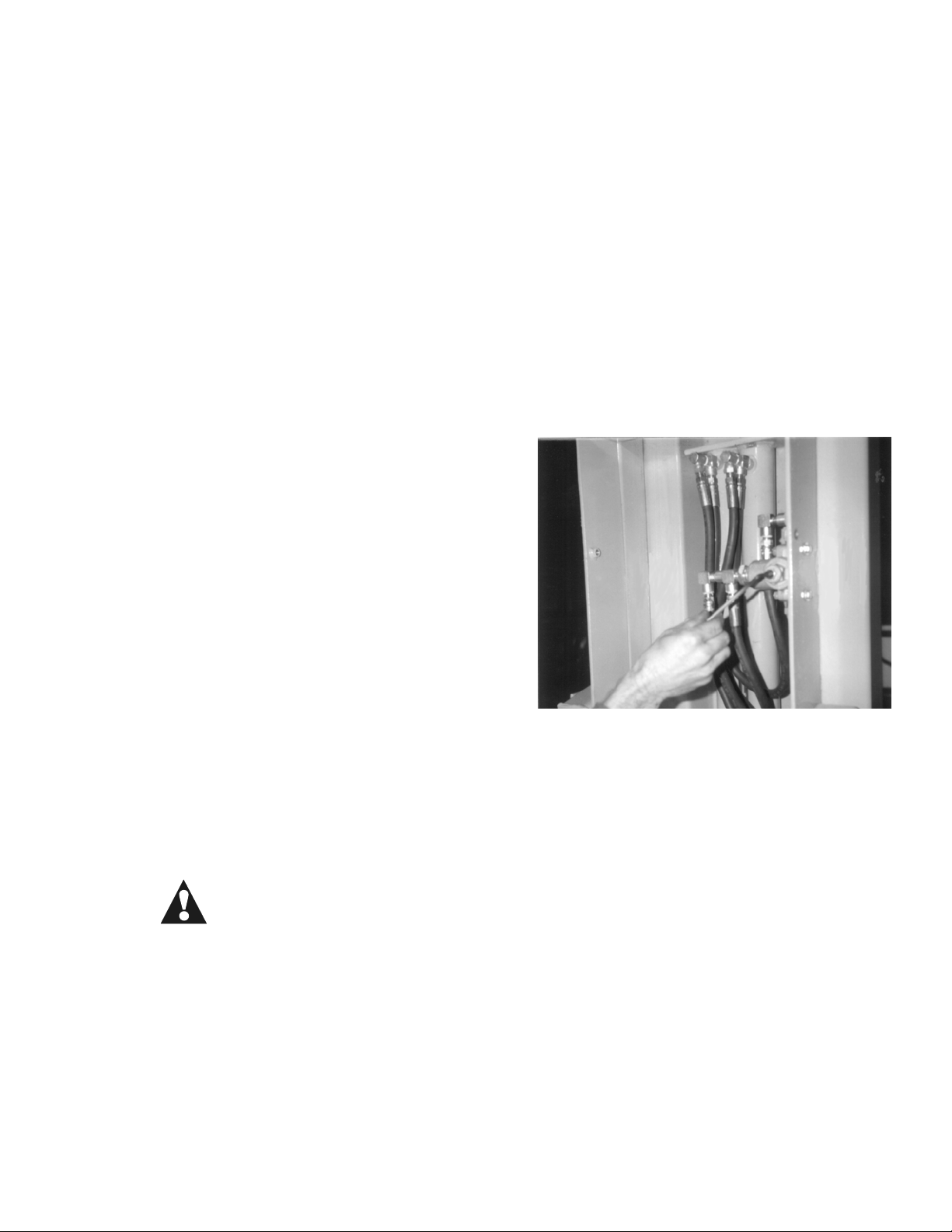
INSTALLING A GRS HYDRAULIC CYLINDER KIT
While the digger is attached to the tractor,
place under safe lifting device, such as a
chain hoist, or electric hoist if available.
Securely attach the chain to the hook eye and
use enough pressure to take the weight of the
mainframe off the turnbuckle and upper brace.
Bolt the hydraulic manifold block to the top of
the hitch as shown in the picture using 1/4” x
4” cap screws, lock washers, and hex nuts. Use
caution not to allow the hydraulic hoses to
drag in the dirt while assembling to help pre-
vent contamination from entering the tractor
hydraulic system. Attach the rod end of the
cylinders to the mainframe with 3/4” X 4-1/2”
bolts and locknuts. Attach the barrel end to
the hitch using 3/4” X 4” bolts and locknuts.
Refer to the parts book for attaching the proper hose to its appropriate location.
Swivel fittings do not need thread tape or other sealant. Stand away from the
drilling machine while removing the lifting device being used. The air in the hy-
draulic cylinders and hoses may allow for retraction or extension of cylinders.
Fully cycle the GRS hydraulic cylinders 2 or 3 times to remove the air from the
lines.
REFER TO THE SECTION ON CHECKING THE LENGTH OF THE DRIVELINE ON THE
NEXT PAGE BEFORE CYCLING THE GRS HYDRAULIC CYLINDERS.
ATTACHING THE DRIVELINE TO THE
GEARBOX AND THE TRACTOR
Remove the tapered bolt in the end of the
torque limiter. Slide the clutch onto the
input shaft of the gearbox until the bolt
hole aligns with the groove in the shaft.
DO NOT FORCE THE SHAFT INTO THE YOKE. Turn
until a smooth fit is allowed. Insert the
tapered bolt and tighten with a wrench.
NOTE: To remove nut from tapered bolt, use
punch to drive head into yoke till taper
will keep bolt from turning with nut.
Next attach the Q.D. front yoke to the tractor PTO
shaft. DO NOT FORCE THE SHAFT INTO THE YOKE. Turn
until a smooth fit is allowed and then push the yoke
onto the tractor output shaft. Line up the pin in the
yoke with the groove in the shaft. After releasing the
Q.D. pin, pull on the yoke to insure a proper fit. If
yoke slides back, it is not properly attached. DO NOT
TAKE A CHANCE. BE SURE THE PTO IS PROPERLY ATTACHED.
LENGTH OF DRIVELINE
If it is necessary to shorten the
driveline, cut both sliding and guard
tubes equally. There should be ap-
proximately 1/2" of sliding tube ex-
posed.

11
BEFORE DRILLING FIRST HOLE
ADJUSTING LOCKBARS
1) With drilling machine mounted on trac-
tor, adjust top link so hitch frame is
square with the ground. Adjust fore and
aft leveling screw (or hydraulic cylinders
on GRS model) so main frame is parallel
with hitch frame.
2) Select a hole in the lockbars, and drop
a 1/2" clevis pin in, so that when the
machine is raised with the 3 point hitch
of the tractor, and the inner shaft on the
lockbars "Bottom Out" against the clevis
pins, the skids on the main frame will be 4" to 6" off the ground. It may be
necessary to try several different holes to find the right one.
NOTE: RAISE THREE POINT HITCH SLOWLY. DO NOT FORCE LOCKBAR AGAINST
PIN. Too much pressure against the pin may shear pins or cause other
damage to the Drilling Machine or Tractor. Be especially careful with
larger tractors, with a powerful lift capacity.
LEVELING DRILLING MACHINE
1) To level machine sideways, use leveling screw on tractor three point hitch.
2) To level machine fore and aft, use leveling turn buckle brace assembly, or
GRS cylinders if machine is so equipped.
3) The hydraulic top link can also be used to level the machine fore and aft.
Use the hydraulic top link to raise machine for transport when moving from
hole to hole, especially over rough ground.
CHECK DRIVELINE -- RELIEF VALVE -- SKIDS
1) BEFORE INSTALLING AUGER: With machine hitched to tractor, thoroughly oil
the inside of the frame tubes and carriage slide tubes with motor oil.
Run the carriage up and down several times. This will serve to "Break
in" the slides. While running up and down observe the telescoping drive-
line shaft to be sure it neither “bottoms out” nor pulls apart. The
driveline as furnished is the correct length for most tractors; however,
some tractors require the driveline to be shortened. This can be done
with a hacksaw (see instructions on previous page). Be sure to file all
burrs smooth, wash away all cuttings and filings, and re-grease shafts
with light grease. With the leveling screw assembly, or GRS hydraulic
cylinders adjust the main frame to a position leaning forward, and to a
position leaning backwards. Observe the driveline while running carriage
up and down to see that it does not "bottom out" or pull apart. On rare
occasions certain tractors may require a longer driveline. If you have a
problem contact the factory for a longer driveline assembly. DO NOT
OPERATE MACHINE IF THE DRIVELINE IS TOO SHORT. IF IT SEPARATES DURING
OPERATION IT COULD CAUSE DAMAGE OR INJURY TO PERSONS.
2) BE SURE RELIEF VALVE IS PROPERLY ADJUSTED: See page 13 for adjusting in-
structions. With auger installed and lockbars locked, carefully apply
down pressure with main hydraulic cylinders. If tractor starts to lift,

12
immediately reverse valve to retract main cylinders, to avoid lifting
tractor wheels off the ground. BE SURE PRESSURE SETTING ON RELIEF VALVE
WILL NOT ALLOW TRACTOR WHEELS TO LIFT OFF THE GROUND. This could cause
damage to auger and break the lower shaft in the gearbox if the tractor
shifts position while losing wheel traction. YOU ALSO RISK UPSETTING THE
TRACTOR, CAUSING SERIOUS INJURY OR EVEN DEATH TO THE OPERATOR OR SOMEONE
CLOSE BY.
Rear wheels must have firm contact with the ground to avoid the tractor
moving while drilling a hole. If the tractor moves while the auger is
in contact with the ground, you risk damage not only to the auger and
gearbox lower shaft, but to the main frame carriage and other parts of
the machine.
3) ADJUST SKIDS ON MAIN FRAME: The main purpose of the adjustable skids is
to protect the auger when transporting the machine. The skids must be ad-
justed so they are well below the lowest point of the auger. Augers may
vary slightly in length due to different teeth, pilots, etc. When chang-
ing augers always check to see that skids are below the auger.
INSTALLING AUGER - With 3 point hitch, raise drilling machine so skids on the
mainframe are approximately 3" off the ground. SHUT OFF TRACTOR ENGINE. Remove
3/4 X 4 bolt which fastens the auger drive stem to the
auger. Next, roll the auger and drive stem under the
hitch support tubes. Now stand auger erect with drive
stem flange directly under gearbox flange. Raise stem
and align holes in flanges and secure with 1/2" bolts
and lockwashers provided; tighten bolts. Align hole in
auger tube with hole in drive stem and replace the 3/4
X 4 bolt, lockwasher and nut. Securely tighten. DO
NOT PERFORM ANY AUGER ASSEMBLY WITH TRACTOR ENGINE
RUNNING.
Never operate or raise or lower gearbox with hands in
the area. If gearbox is lowered with fingers or hand
between auger flange and gearbox flange, they could be
mashed, causing severe injury or even permanent loss
of fingers and hand. BE SAFE - BE SURE TRACTOR ENGINE
IS NOT RUNNING ANY TIME YOU APPROACH THE AUGER.
13
CHECK LIST - BEFORE STARTING A NEW DIGGER
|Check bolts for tightness with a wrench.
|Check auger for interference.
|Check that all hitch pins are in place and secured.
|Check that driveline is secured to tractor PTO and gearbox
|Check driveline length.
|Check that all shields are in place and operable.
TO ADJUST THE RELIEF VALVE
Remove the adjustment cap and loosen the
locknut using a 1/2" wrench. Use a 3/16"
allen wrench to adjust the pressure setting.
Turn allen wrench counter clockwise to re-
duce the pressure and clockwise to increase
pressure. BELLTEC recommends that the re-
lief pressure be adjusted to the minimum PSI
setting that will accomplish the digging
task to be performed.
Be sure that the pressure is adjusted
low enough that the tractor wheels will not be lifted from the
ground when down pressure is applied to the auger.
NEVER EXCEED 1500 PSI.

14
TRANSPORTING
When driving on a road or highway at night or during the day, use accessory
lights and devises for adequate warning to operators of other vehicles. Acces-
sory lights for the Belltec Digger are available from your dealer. Check local
governmental regulations for the proper use and requirements.
DON'T TRAVEL AFTER DARK WITHOUT PROPER LIGHTS OR REFLECTORS
Clean the SMV (Slow Moving Vehicle) emblem before operating
or transporting the Belltec Drilling Machine on a road or
highway.
Do not allow anyone to ride on the digger when it is being
moved. Become familiar with the physical size of your dig-
ger. Pay particular note to its height and watch for any obstructions such as
power lines, telephone lines, and tree limbs, etc.
REMEMBER - SAFETY IS NOT AN ACCIDENT
LUBRICATION
A) FILLER PLUG
B) CHECK PLUG
C) DRAIN PLUG
D) GREASE ZERK
GEARBOX....The gearbox has been lubricated before shipment. If oil is observed
leaking from the lower seal or the front seal, remove the gearbox from the
mounting supports and check the oil level. If level is low it may be necessary
to replace the seals and refill the gearbox.
If machine is in constant use, once each month apply 5 or 6 pumps of grease to
the grease zerk (D) from a standard hand held grease gun using a good grade of
bearing grease.
EACH DAY BEFORE USE.... Check gearbox for signs of leaking around seals. Occa-
sionally, seals will leak if unit sits for a prolonged period of time, however,
they should quit leaking after using and getting soaked with oil. If they do
not quit leaking replace at once and refill gearbox.
ANNUALLY....Remove gearbox and change oil. Use 1 gallon of SA 90 EP gear oil.
Do not overfill the gearbox. Fill only to the check plug (B).
DRIVELINE....The driveline should be disconnected from the Tractor, pulled
apart, and inspected periodically. If the shaft is "gummy" it should be washed
in solvent. Always, before putting back together put sufficient grease on ends
of tube so that the full contact area will be filmed with a coat of grease.
DAILY....Grease the universal joint cross zerks with a hand held grease gun.
Align nylon grease fitting located on end of outer shaft with hole in outer
shield and grease with grease gun.

15
MAIN FRAME SLIDE TUBES....Keep inside of tubes free of grit and debris. Clean
with a high pressure washer or a swab and solvent. Lubricate inside of tubes
and gearbox carriage slides liberally with motor oil.
OPERATING INSTRUCTIONS
1) Spot auger pilot over mark where hole is to be drilled. LOCK TRACTOR
BRAKES---if tractor rolls forward or backwards with auger in the ground, the
auger, gearbox, carriage or frame may be damaged or broken.
2) LEVEL THE MACHINE BEFORE STARTING TO DRILL. Be careful that you do not
change the angle of the machine with the Hydraulic top link, or the GRS hy-
draulic leveling cylinders, after starting to drill. This could cause the
lower gearbox shaft to bend or break or cause other damage to the drilling
machine.
3) When drilling rock or other hard material, and the drilling machine angle
changes when down pressure is applied, due to slack in the tractor 3 point
hitch members, you may want to compensate by starting with the machine lean-
ing back enough so that when full pressure is applied the machine will be
straight or at the angle you want to drill.
4) OPTIMUM AUGER RPM will vary with type of drilling or soil conditions, etc.
Generally, however, when drilling rock with a rock auger, or digging in
chunky rock, PTO speed should not exceed 100-120 RPM. If digging in dirt a
PTO speed of up to 300 RPM can be used. Experience will show what PTO speed
will dig or drill best and give the best tooth life.
5) To clean the hole, it is recommended that you run the auger in and out of
the hole several times; each time shut off PTO and bring the auger out not
turning. When auger is clear of the hole, snap auger in gear, and spin dirt
off the auger. Of course, some sandy soils, or dry powder dirt soils make
it very difficult to get a clean hole with the auger. Some professional
drillers add a little water to the hole. Sometimes it is necessary to clean
the hole by hand.
6) When drilling holes in a straight line, and on level terrain the skids can
be left 4" to 6" off the ground while drilling. By doing this, you can move
from hole to hole without lifting the machine with hydraulic top link or the
tractor 3 point hitch. DO NOT DRAG MACHINE ON SKIDS. Be sure main frame is
raised high enough to clear ground when crossing ditches or uneven ground,
and will clear all obstructions. BE CAREFUL WHEN BACKING UP NOT TO DAMAGE
LOWER PART OF MAIN FRAME.
7) OPERATING HYDRAULIC TOP LINK---Before starting to drill a hole, level the
machine by extending or retracting the hydraulic top link cylinder. If
starting a hole on "bare" rock with a rock auger, stabilize the unit by ex-
tending the top link cylinder to apply pressure to the mainframe skids. If
area is uneven raise or lower one of the skids to compensate, so the machine
will not tilt sideways when pressure is applied to the skids. Retract the
top link cylinder to raise mainframe when transporting with lockbar pins in
place.
8) USING HITCH LOCKBARS---The lockbars are designed to lock the 3 point hitch
down when drilling where the weight of the tractor is utilized to drill in
hard conditions. If drilling soil only, often the weight of the drilling
machine and hitch members are sufficient, and it is not necessary to use the
lockbars.
When using lockbars, select a pin hole which will allow the 3 point hitch to
raise the machine skids approximately 4 inches off the ground when the inner
shaft "bottoms" out against the pins. DO NOT FORCE 3 POINT HITCH AGAINST THE
PINS. Just ease the 3 point up until the inner shafts are firmly against the
pins.
IF TRACTOR IS EQUIPPED WITH A DRAFT CONTROL, set it in off position. On some
tractors it may be necessary to disable the draft control. Your tractor dealer

16
can advise you on this.
10) USING THE AUGER EXTENSION---Drill hole part way. Stop PTO, and shut off
tractor engine. Remove 3/4" bolt through auger and drive stem. Start trac-
tor engine and raise gearbox till hole in the top of the auger is aligned
with the hole in the drive stem. AGAIN SHUT OFF TRACTOR ENGINE. Replace
the bolt through the auger and drive stem, and continue drilling the hole
until desired depth is reached. To bring auger out of the ground, raise
gearbox to full height. SHUT OFF TRACTOR. Block auger up with a piece of
2x4 lumber, or other blocking material, to keep auger from falling back into
the hole. Remove bolt from auger and drive stem. Start tractor engine and
lower gearbox till holes in auger and drive stem are aligned. SHUT OFF
TRACTOR ENGINE and replace the bolt. Remove the block from auger and raise
to full raised position.
DANGER: BE SAFE---DO NOT PERFORM ANY WORK AROUND MACHINE
WITH TRACTOR ENGINE RUNNING. Serious in-
jury or death could be the result if body
parts such as hands or feet are caught in
turning machine elements, or under the
force of hydraulic pressure.
When using the extension, dirt or other debris may accu-
mulate in the auger tube, therefore, frequently remove the
drive stem from the auger tube and clean it out. If dirt is
allowed to become impacted, the drive stem will be prevented
from going to the bottom of the tube and the holes will not align.
11) KEEP MAIN FRAME SLOTTED TUBES CLEAN---and free of dirt and other debris.
Occasionally, clean tubes with a high pressure washer, or a swab and sol-
vent. Oil inside of tubes and gearbox carriage slide tubes liberally with
motor oil. DO NOT USE GREASE.
DRILLING HOLES IN DIRT---SSA series augers are equipped with cast steel replace-
able teeth boring heads, and are designed to drill holes in hard dirt, stony
dirt, soft dirt, and even some soft solid rock. Some suggestions follow:
Adjust relief valve to lowest setting which will accomplish your job.
When digging in soft dirt, or where tree roots are present, keep your hand on
the hydraulic valve and lower auger in increments a little at a time, to avoid
"corkscrewing" the auger and risk getting it stuck.
If you experience excessive tooth breakage when digging stony soil, try using
5T30 spike teeth in all the pockets.
For digging in abrasive soils, hardfaced teeth are available.
When drilling abrasive frozen soils or soft solid rock, 1335 carbide insert
teeth may work best.
DRILLING SOLID ROCK---Obviously, there are many variables in drilling solid
rock. Hardness of the rock, amount of down pressure available, size of the au-
ger, speed (RPM) of the auger, are a few of the things that will affect the
drill rate, or even the feasibility of being able to drill any specific solid
rock. This can only be determined on the site to be drilled. Although the
BELLTEC drilling machine is successfully drilling solid rock in many parts of
the country, we cannot in any way guarantee results at every location.
Rock can also be highly abrasive, causing excessive tooth wear. Of course
BELLTEC has no control over these conditions. Many users are getting 100 or
more holes before replacing any teeth. On the other hand some rock will wear
out teeth in just a few holes. Many operators of trenchers and commercial
drilling machines experience these same results from similar conditions. The
SRA, THC, or RAD series augers are usually best for drilling solid rock.

17
Under most conditions it is best to run the auger slowly. In most cases 30 to
40 RPM auger speed seems to give the best drill rate and wear on the teeth.
This would be 100 to 120 RPM PTO speed.
To improve drill rate, occasionally relieve the down pressure on the auger.
This seems to let the teeth "take a bite".
DRILLING LARGE CHUNK ROCK---This is probably the toughest of all drilling condi-
tions, and certainly can be the most destructive to both the equipment and
drilling elements. Since the teeth will encounter frequent severe impacts, an
experienced operator must use care and get the feel of allowing the auger to
find its way down through the rocks.
RAD series augers give the best service in most cases under these conditions.
PUFF DRILL---This is a solid steel shaft equipped with a special carbide cutting
head for drilling 2" holes in rock or concrete. We call it the puff drill be-
cause it will build up down hole pressure and the cuttings will blow out of the
hole. FOR BEST RESULTS OBSERVE THE FOLLOWING:
1) Run PTO at 100 to 200 RPM. Excessive speed can cause cutting head to over-
heat.
2) Relieve the down pressure on the cutting head frequently. TOO MUCH
CONSTANT DOWN PRESSURE MAY CAUSE PARTICLES TO BE BLOWN AT A FORCE
SUFFICIENT TO CAUSE INJURY TO PERSONS OR EQUIPMENT. Too much down pressure
may also cause the cutting head to over heat or cause excessive wear.
3) Very abrasive rock may cause excessive wear and shorten the life of the
cutting head.
4) ALWAYS WEAR GOGGLES WHEN OPERATING THE PUFF. ALWAYS REQUIRE WORKERS OR
BYSTANDERS, IN THE AREA, TO WEAR GOGGLES WHEN THE PUFF IS BEING OPERATED.
PARTICLES OF ROCK CAN BE BLOWN 20 FEET OR MORE, WITH ENOUGH FORCE TO CAUSE
INJURY TO EYES OR OTHER BODY PARTS. KEEP ALL BYSTANDERS AT LEAST 20 FEET
AWAY FROM MACHINE WHEN IN OPERATION.
MAINTENANCE
CHECK AND TIGHTEN ALL BOLTS.
LUBRICATE, following previous instructions found elsewhere.
DAILY MAINTENANCE:
⇒CHECK AND TIGHTEN ALL BOLTS
⇒INSPECT AUGERS FOR UNUSUAL WEAR.
RENEW HARDFACED AREAS WHEN WEAR IS NOTICED.
⇒REPLACE WORN BITS AND CUTTING TEETH.
⇒INSPECT ALL SAFETY SHIELDS. REPAIR OR REPLACE IF NOT
IN PROPER WORKING ORDER.
⇒LUBRICATE UNIVERSAL JOINTS AND DRIVELINE SHAFT.
⇒LUBRICATE MAINFRAME TUBES AND CARRIAGE SLIDES.
INSPECT MACHINE REGULARLY:
Repair or replace any worn parts. Remember that earth boring can be hard work
for any machine. Under extreme conditions parts can wear or break. Using any
machine without proper maintenance of all parts can cause further damage to good
parts.

18
AUGER MAINTENANCE: dirt, sand, rock cuttings, or other debris may filter into
the square tube of the auger, preventing alignment of the lower hole in the
square shaft drive stem. If allowed to become impacted, the pressure of the end
of the square shaft could cause the debris to expand and split the tube. If
necessary, remove the pilot from center of the auger and drive dirt out with a
rod or a shaft.
On rock augers, watch the hardfacing, if worn
away, re hardface. Failure to do so will allow
excessive wear on pockets, and will ruin auger.
We trust you will find the information in this book
helpful to your successful operation of the BELLTEC
DRILLING MACHINE. We realize that it is not possible
to cover every condition that may be found in the sometime complicated job of
drilling holes in mother earth.
However, we want to be helpful in any way we
can, therefore, we invite you to call us when
you need assistance, that you may receive the
satisfaction that hundred of others have found
with this unique machine.
This manual suits for next models
1
Table of contents


