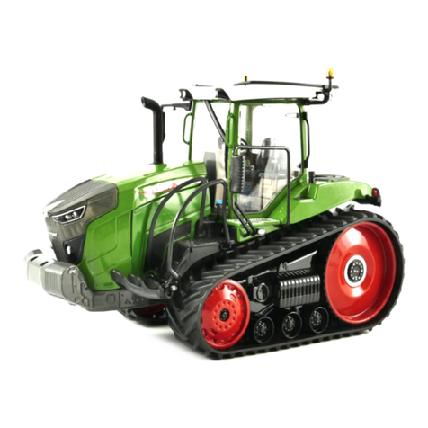
FENDT 500 Vario S4 User manual

Workshop Service ManualFENDT 500 Vario S4
FENDT 512 Vario S4FENDT 513 Vario S4 FENDT 514 Vario S4 FENDT 516 Vario S4
Marktoberdorf
AGCO GmbH - Johann-Georg-Fendt-Str. 4 - D-87616 Marktoberdorf
FENDT is a worldwide brand of AGCO
© AGCO 2017
July 2017
X990.005.549.012
5174
English
epcatalogs.com

Subject to changes and additions
IMPORTANT:
This document is valid from the chassis number noted. The last valid chassis number could not be
determined at the time of creation. Use AGCONET or contact FENDT technical service to make sure
whether a current wiring diagram set is available with an updated chassis number range.
Due to further developments to the vehicle, the content of this document is subject to change.
The relevant accident prevention regulations must be observed, as must as any generally acknowledged
safety, industrial medicine and traffic regulations. The manufacturer does not accept liability for damage
resulting from unauthorized modifications to the machine.
Property of AGCO GmbH.
Any disclosure to third parties—either in return for payment or free of charge—is prohibited.
GUID-A9F19094-7C5D-44B1-84C7-6D95E6AC44E4 [V2]
.
FENDT 500 Vario S4
X990.005.549.012
epcatalogs.com

FENDT 500 Vario S4
1 0000 - tractor .............................................................1-1
1.1 General ........................................................... 1-3
1.1.1 General advice ..................................................1-3
1.1.2 Notes on documentation ...........................................1-3
1.1.3 Safety briefing and measures ........................................1-4
1.1.4 Biodegradable hydraulic oil ..........................................1-7
1.1.5 Tightening torques for bolts in Nm (kpm) ...............................1-8
1.1.6 Assignment table FENDT T types to the EU Type Approval Number ............1-9
1.1.7 Importance of and position of the safety decals ..........................1-10
1.1.8 Change wheels .................................................1-21
1.1.9 Location of the identification plates ..................................1-24
1.2 Technical specification ............................................1-28
1.2.1 Technical data: 0000 general .......................................1-28
1.2.2 Technical data: 1000 transmission ...................................1-29
1.2.3 Technical specification: Engine ......................................1-36
1.2.4 Technical data: 3000 front axle ......................................1-43
1.2.5 Technical data: 4000 steering .......................................1-45
1.2.6 Technical data: 5500 air conditioning system/8100 cab/8600 EPC control valve ...1-45
1.2.7 Technical data: 8800 compressed air system / 9000 electrical system / 9200 front
power lift ..........................................................1-46
1.2.8 Technical data: 9600 hydraulic equipment ..............................1-47
1.3 Faults ............................................................1-51
1.3.1 Note on the fault code table ........................................1-51
1.3.2 Confirming, calling up, deleting fault codes .............................1-51
1.3.3 Fault code 00.0.00 - ..............................................1-53
1.3.4 Fault code 01.0.00 - ..............................................1-57
1.3.5 Fault code 02.0.00 - ..............................................1-63
1.3.6 Fault code 03.1.00 - ..............................................1-65
1.3.7 Fault code 04.1.00 - ..............................................1-67
1.3.8 Fault code 05.1.00 - ..............................................1-78
1.3.9 Fault code 06.1.00 - ..............................................1-82
1.3.10 Fault code 07.1.00 - .............................................1-89
1.3.11 Fault code 08.1.00 - .............................................1-91
1.3.12 Fault code 09.1.00 - .............................................1-97
1.3.13 Fault code 0A.1.00 - ............................................1-102
1.3.14 Fault code 0B.1.00 - ............................................1-114
1.3.15 Fault code 0D.1.00 - ............................................1-118
1.3.16 Fault code 0E.1.00 - ............................................1-120
1.3.17 Fault code 0F.1.00 - ............................................1-125
1.3.18 Fault code 10.1.00 - ............................................1-129
1.3.19 Fault code 11.1.00 - ............................................1-131
1.3.20 Fault code 14.1.00 - ............................................1-132
1.3.21 Fault code 15.1.00 - ............................................1-135
1.3.22 Fault code 17.1.00 – ...........................................1-136
1.3.23 Fault code 18.1.00 - ............................................1-137
1.3.24 Fault code 1D.0.00 - ............................................1-140
1.3.25 Fault code 1F.1.00 - ............................................1-151
1.3.26 Fault code 20.1.00 – ...........................................1-152
1.3.27 Fault messages: manual air conditioning system .......................1-156
1.3.28 Calibration fault codes ..........................................1-157
1.3.29 List of fault codes for Deutz TCD/TTCD 4.1/6.1/7.8 engines ...............1-169
Table of contents
FENDT 500 Vario S4
X990.005.549.012
epcatalogs.com

1.4 Component position .............................................1-243
1.4.1 Electrical/electronic components - A .................................1-243
1.4.2 Electrical/electronic components - B .................................1-249
1.4.3 Electrical/electronic components - E .................................1-261
1.4.4 Electrical/electronic components - F .................................1-269
1.4.5 Electrical/electronic components - G .................................1-270
1.4.6 Electrical/electronic components - H .................................1-271
1.4.7 Electrical/electronic components – K .................................1-272
1.4.8 Electrical/electronic components - M ................................1-274
1.4.9 Electrical/electronic components - R .................................1-277
1.4.10 Electrical/electronic components - S ................................1-279
1.4.11 Electrical/electronic components - X ................................1-285
1.4.12 Electrical/electronic components - Y ................................1-326
1.4.13 Hydraulic components ..........................................1-333
1.5 Settings and calibration ..........................................1-348
1.5.1 General information on calibration ..................................1-348
1.5.2 Calibration code 8001 8002 (Rear EPC) ...............................1-352
1.5.3 Calibration code 9001 9002 (Front EPC) ..............................1-358
1.5.4 Calibration code 1001 (crossgate lever) ...............................1-364
1.5.5 Calibration code (1003 ... 1006) (linear module) .........................1-370
1.5.6 Calibration code 7666 (front axle suspension) ..........................1-373
1.5.7 Calibration code 2401 (steering angle sensor) ..........................1-375
1.5.8 Calibration code 2403 (VarioGuide steering valve) .......................1-385
1.5.9 Calibration code 6034 (rear PTO clutch) ...............................1-388
1.5.10 Calibration code 7034 (front PTO clutch) .............................1-390
1.5.11 Calibration code 4001 (clutch pedal) ................................1-393
1.5.12 Calibration code 4002 (hand throttle) ................................1-395
1.5.13 Calibration code 4003 (travel range selector) ..........................1-398
1.5.14 Calibration code 4005 (foot throttle/accelerator pedal) ...................1-401
1.5.15 Calibration code 4007 (transmission ratio characteristic) ..................1-403
1.5.16 Calibration code 4009 (turbo-clutch function) ..........................1-408
1.5.17 Calibration code 4010 (accelerator pedal resolution) .....................1-411
1.5.18 Calibrating the heater valve (no code) ...............................1-414
1.5.19 Calibration of the heater valve — manual air conditioning system ...........1-415
1.5.20 Calibrating speed display ........................................1-416
1.5.21 Calibration fault codes ..........................................1-419
2 1000 - Transmission .......................................................2-1
2.1 Gearbox control ................................................... 2-3
2.1.1 Transmission function diagram .......................................2-3
2.1.2 Transmission emergency mode ......................................2-9
2.1.3 Transmission control system functional sequence ........................2-12
2.1.4 Gearbox hydraulics wiring diagram — 416.100.000.002 ....................2-17
2.1.5 Position of transmission components .................................2-20
2.1.6 Measuring transmission pressure ....................................2-26
2.1.7 Transmission pressure measurement (fax template) ......................2-27
2.1.8 Hydraulic pressure measuring points on transmission and comfort controls .....2-29
2.1.9 Transmission comfort control functions pressure measurement report: Fax
template. ..........................................................2-32
2.2 Differential unit ...................................................2-34
2.2.1 Remove differential ..............................................2-34
2.2.2 Disassemble and reassemble the differential ...........................2-39
2.2.3 Adjusting the roll resistance of the taper roller bearing on the differential gear ...2-51
2.2.4 Dismantling the pinion shaft ........................................2-52
2.2.5 Disassemble and reassemble the pinion shaft ...........................2-56
2.2.6 Adjusting the roll resistance of the pinion shaft ..........................2-61
2.2.7 Check and adjust the crown wheel to the pinion. ........................2-63
Table of contents
FENDT 500 Vario S4
X990.005.549.012
epcatalogs.com

2.3 Brake system .....................................................2-67
2.3.1 Hydraulic brake system ...........................................2-67
2.3.2 Dismantle rear wheel brake ........................................2-68
2.3.3 Install rear wheel brake ...........................................2-72
2.3.4 Adjusting rear wheel brake .........................................2-79
2.3.5 Setting for brake pedals and "booster" brake master cylinder ................2-81
2.3.6 Use the transmission filling pump to bleed the brake hydraulics ..............2-86
2.3.7 Bleed the hydraulic brake system ....................................2-87
2.3.8 Adjust the parking brake (hand brake) .................................2-89
2.4 Vario insert .......................................................2-91
2.4.1 Remove the Vario CVT unit ........................................2-91
2.4.2 Fit the Vario insert ..............................................2-109
2.4.3 2V3/2V4 high-pressure limiting valve .................................2-131
2.4.4 Function of flushing valve 2V5 .....................................2-132
2.4.5 Replacing high-pressure limiting valve ................................2-133
2.4.6 Replacing the flushing valve .......................................2-134
2.4.7 Top up the transmission oil .......................................2-135
2.4.8 Installing A009 actuator unit .......................................2-136
2.5 Front PTO .......................................................2-140
2.5.1 Technical drawing of front PTO ....................................2-140
2.5.2 Front PTO - System pressure and clutch pressure .......................2-145
2.5.3 Remove front PTO ..............................................2-147
2.5.4 Fit front PTO ..................................................2-151
2.5.5 Remove front PTO clutch .........................................2-155
2.5.6 Fit the front PTO clutch ..........................................2-160
2.6 Live PTO .........................................................2-170
2.6.1 Removing and installing the rear PTO clutch ...........................2-170
2.6.2 Disassemble the rear PTO transmission ..............................2-189
2.6.3 Assemble the rear PTO transmission ................................2-197
2.6.4 Adjusting PTO axial play ..........................................2-219
2.6.5 Adjusting the shift rod axial play ....................................2-221
2.6.6 Adjusting the overrun on the control forks .............................2-224
2.7 Front wheel drive ................................................2-228
2.7.1 Removing and dismantling the front wheel drive clutch ...................2-228
2.7.2 Assemble and install the front-wheel drive clutch .......................2-233
2.8 Hydrodamp ......................................................2-243
2.8.1 Remove the hydrodamp ..........................................2-243
2.8.2 Fit the hydrodamp ..............................................2-246
3 2000 - Engine .............................................................3-1
3.1 2000 - Engine ......................................................3-3
3.1.1 Malfunctions in the common rail diesel engine ...........................3-3
3.1.2 Fax template for determining the specific engine lubricating oil consumption ....3-14
3.1.3 Determining engine power - comparison of standards and directives ..........3-18
3.1.4 PTO power measurement .........................................3-19
3.1.5 General description of the common rail system ..........................3-21
3.1.6 Emergency operation (emergency function) ............................3-25
3.1.7 Deutz Common Rail principle .......................................3-26
3.1.8 A099 engine control ECU (EDC 17) ...................................3-28
3.1.9 B055 - foot throttle sensor .........................................3-32
3.1.10 B085 camshaft speed sensor ......................................3-33
3.1.11 B086 rail pressure sensor .........................................3-35
3.1.12 B087 fuel low pressure sensor .....................................3-37
3.1.13 B088 - sensor, crankshaft speed ....................................3-37
3.1.14 B089 engine temperature sensor (Deutz) .............................3-39
3.1.15 B090 oil pressure sensor .........................................3-39
3.1.16 B091 - water in fuel sensor .......................................3-40
Table of contents
FENDT 500 Vario S4
X990.005.549.012
epcatalogs.com
This manual suits for next models
4
Table of contents
Other FENDT Tractor manuals

FENDT
FENDT 900 Vario Gen6 Series User manual
FENDT
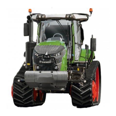
FENDT Vario MT 938 User manual

FENDT
FENDT Vario 900 Series User manual
FENDT
FENDT Vario 700 Series User manual
FENDT
FENDT 5275 C User manual

FENDT
FENDT 1149MT User manual
FENDT
FENDT Vario 712 User manual

FENDT
FENDT FAVORIT 900 Instruction manual

FENDT
FENDT 916 Vario User manual
FENDT
FENDT New Leader NL4330G4 User manual

